CONUS - Holloman AFB IFS

Status
Active
View/Download
Publish Date
Size
50.2 MB
Pages
125
Service Type
Air Force Active Duty

This Installation Facilities Standards (IFS) document is part of the Air Force Corporate Facilities Standards (AFCFS) program and provides facility design standards for Holloman Air Force Base. IFS replaces the Design Compatibility Standards (and similar legacy documents), as a component plan of the Installation Development Plan (IDP). For more information contact the Base Civil Engineer.

CONUS - Hurlburt Field IFS

Status
Active
View/Download
Publish Date
Size
76.8 MB
Pages
143
Service Type
Air Force Active Duty

This Installation Facilities Standards (IFS) document is part of the Air Force Corporate Facilities Standards (AFCFS) program and provides facility design standards for Hurlburt Field. IFS replaces the Design Standards documents (and similar legacy documents), as a component plan of the Installation Development Plan (IDP). For more information contact the Base Civil Engineer.

CONUS - JB Anacostia-Bolling IFS

Status
Active
View/Download
Publish Date
Size
85.5 MB
Pages
176
Cover
Image
JB Anacostia-Bolling IFS Cover
Service Type
Air Force Active Duty

This Installation Facilities Standards (IFS) document is part of the Air Force Corporate Facilities Standards (AFCFS) program and provides facility design standards for JB Anacostia-Bolling. IFS replaces the Installation Appearance Plan (and similar legacy documents) and is required by Air Force Instruction (AFI) 32-1023. For more information contact the Base Civil Engineer.

CONUS - JB Andrews IFS

Status
Active
View/Download
Publish Date
Size
76.3 MB
Pages
154
Service Type
Air Force Active Duty

This Installation Facilities Standards (IFS) document is part of the Air Force Corporate Facilities Standards (AFCFS) program and provides facility design standards for JB Andrews. IFS replaces the Architectural Compatibility Plan (and similar legacy documents) and is required by Air Force Instruction (AFI) 32-1023. For more information contact the Base Civil Engineer.

CONUS - JB Charleston IFS

Status
Active
View/Download
Publish Date
Size
95.2 MB
Pages
181
Service Type
Air Force Active Duty

This Installation Facilities Standards (IFS) document is part of the Air Force Corporate Facilities Standards (AFCFS) program and provides facility design standards for Joint Base Charleston. IFS replaces the Architectural Compatibility Plan (and similar legacy documents), as a component plan of the Installation Development Plan (IDP). For more information contact the Base Civil Engineer.

CONUS - JBLE Eustis IFS

Status
Active
View/Download
Publish Date
Size
81.4 MB
Pages
155
Service Type
Air Force Active Duty

This Installation Facilities Standards (IFS) document is part of the Air Force Corporate Facilities Standards (AFCFS) program and provides facility design standards for JBLE Eustis. IFS replaces the Installation Design Guide document (and similar legacy documents), as a component plan of the Installation Development Plan (IDP). For more information contact the Base Civil Engineer.

CONUS - JBLE Langley IFS

Status
Active
View/Download
Publish Date
Size
44.6 MB
Pages
148
Service Type
Air Force Active Duty

This Installation Facilities Standards (IFS) document is part of the Air Force Corporate Facilities Standards (AFCFS) program and provides facility design standards for Joint Base Langley-Eustis, Vol. 1: JBLE Langley. IFS replaces the Architectural Compatibility Plan (and similar legacy documents), as a component plan of the Installation Development Plan (IDP). For more information contract the Base Civil Engineer.

CONUS - JBMDL Dix IFS

Status
Active
View/Download
Publish Date
Size
34.2 MB
Pages
134
Service Type
Air Force Active Duty

This Installation Facilities Standards (IFS) document is part of the Air Force Corporate Facilities Standards (AFCFS) program and provides facility design standards for JBMDL Dix. IFS replaces the Installation Design Standards (and similar legacy documents), as a component plan of the Installation Development Plan (IDP). For more information contact the Base Civil Engineer.

CONUS - JBMDL Lakehurst IFS

Status
Active
View/Download
Publish Date
Size
36.4 MB
Pages
140
Service Type
Air Force Active Duty

This Installation Facilities Standards (IFS) document is part of the Air Force Corporate Facilities Standards (AFCFS) program and provides facility design standards for JBMDL Lakehurst. IFS replaces the Installation Design Standards (and similar legacy documents), as a component plan of the Installation Development Plan (IDP). For more information contact the Base Civil Engineer.

CONUS - JBMDL McGuire IFS

Status
Active
View/Download
Publish Date
Size
34.3 MB
Pages
135
Service Type
Air Force Active Duty

This Installation Facilities Standards (IFS) document is part of the Air Force Corporate Facilities Standards (AFCFS) program and provides facility design standards for JBMDL McGuire. IFS replaces the Architectural Compatibility Plan (and similar legacy documents), as a component plan of the Installation Development Plan (IDP). For more information contact the Base Civil Engineer.

CONUS - JBSA Lackland IFS

Status
Active
View/Download
Publish Date
Size
43 MB
Pages
145
Service Type
Air Force Active Duty

This Installation Facilities Standards (IFS) document is part of the Air Force Corporate Facilities Standards (AFCFS) program and provides facility design standards for Joint Base San Antonio Lackland. IFS replaces the Architectural Compatibility Plan (and similar legacy documents), as a component plan of the Installation Development Plan (IDP). For more information contact the Base Civil Engineer.

CONUS - JBSA Randolph IFS

Status
Active
View/Download
Publish Date
Size
38.7 MB
Pages
141
Service Type
Air Force Active Duty

This Installation Facilities Standards (IFS) document is part of the Air Force Corporate Facilities Standards (AFCFS) program and provides facility design standards for JBSA Randolph. IFS replaces the Architectural Compatibility Standards (and similar legacy documents), as a component plan of the Installation Development Plan (IDP). For more information contact the Base Civil Engineer.

CONUS - JBSA Sam Houston IFS

Status
Active
View/Download
Publish Date
Size
70 MB
Pages
147
Service Type
Air Force Active Duty

This Installation Facilities Standards (IFS) document is part of the Air Force Corporate Facilities Standards (AFCFS) program and provides facility design standards for JBSA Sam Houston. IFS replaces the Installation Design Guide (and similar legacy documents), as a component plan of the Installation Development Plan (IDP). For more information contact the Base Civil Engineer.

CONUS - Keesler AFB IFS

Status
Active
View/Download
Publish Date
Size
52.7 MB
Pages
142
Service Type
Air Force Active Duty

This Installation Facilities Standards (IFS) document is part of the Air Force Corporate Facilities Standards (AFCFS) program and provides facility design standards for Keesler Air Force Base. IFS replaces the Installation Design Standards (and similar legacy documents), as a component plan of the Installation Development Plan (IDP). For more information contact the Base Civil Engineer.

CONUS - Kirtland AFB IFS

Status
Active
View/Download
Publish Date
Size
70.6 MB
Pages
142
Service Type
Air Force Active Duty

This Installation Facilities Standards (IFS) document is part of the Air Force Corporate Facilities Standards (AFCFS) program and provides facility design standards for Kirtland Air Force Base. IFS replaces the Architectural Compatibility Plan (and similar legacy documents), as a component plan of the Installation Development Plan (IDP). For more information contact the Base Civil Engineer.

CONUS - Laughlin AFB IFS

Status
Active
View/Download
Publish Date
Size
86.1 MB
Pages
144
Service Type
Air Force Active Duty

This Installation Facilities Standards (IFS) document is part of the Air Force Corporate Facilities Standards (AFCFS) program and provides facility design standards for Laughlin Air Force Base. IFS replaces the Design Standards document (and similar legacy documents), as a component plan of the Installation Development Plan (IDP). For more information contact the Base Civil Engineer.

CONUS - Little Rock AFB IFS

Status
Active
View/Download
Publish Date
Size
77.9 MB
Pages
155
Service Type
Air Force Active Duty

This Installation Facilities Standards (IFS) document is part of the Air Force Corporate Facilities Standards (AFCFS) program and provides facility design standards for Little Rock Air Force Base. IFS replaces the Architectural Compatibility Plan (and similar legacy documents), as a component plan of the Installation Development Plan (IDP). For more information contact the Base Civil Engineer.

CONUS - Los Angeles AFB IFS

Status
Active
View/Download
Publish Date
Size
30 MB
Pages
127
Service Type
Air Force Active Duty

This Installation Facilities Standards (IFS) document is part of the Air Force Corporate Facilities Standards (AFCFS) program and provides facility design standards for Los Angeles Air Force Base. IFS replaces the Facilities Excellence Plan (and similar legacy documents), as a component plan of the Installation Development Plan (IDP). For more information contact the Base Civil Engineer.

CONUS - Luke AFB IFS

Status
Active
View/Download
Publish Date
Size
53.2 MB
Pages
144
Service Type
Air Force Active Duty

This Installation Facilities Standards (IFS) document is part of the Air Force Corporate Facilities Standards (AFCFS) program and provides facility design standards for Luke Air Force Base. IFS replaces the Architectural Compatibility Guide (and similar legacy documents), as a component plan of the Installation Development Plan (IDP). For more information contact the Base Civil Engineer.

CONUS - MacDill AFB IFS

Status
Active
View/Download
Publish Date
Size
43 MB
Pages
128
Service Type
Air Force Active Duty

This Installation Facilities Standards (IFS) document is part of the Air Force Corporate Facilities Standards (AFCFS) program and provides facility design standards for MacDill Air Force Base. IFS replaces the Architectural Compatibility Plan (and similar legacy documents), as a component plan of the Installation Development Plan (IDP). For more information contract the Base Civil Engineer.

CONUS - Malmstrom AFB IFS

View/Download
Publish Date
Size
113.9 MB
Pages
163
Service Type
Air Force Active Duty

This Installation Facilities Standards (IFS) document is part of the Air Force Corporate Facilities Standards (AFCFS) program and provides facility design standards for Malmstrom Air Force Base. IFS replaces the Facilities Excellence Plan (and similar legacy documents) and is required by Air Force Instruction (AFI) 32-1023. For more information contact the Base Civil Engineer.

CONUS - Maxwell AFB IFS

Status
Active
View/Download
Publish Date
Size
58 MB
Pages
145
Service Type
Air Force Active Duty

This Installation Facilities Standards (IFS) document is part of the Air Force Corporate Facilities Standards (AFCFS) program and provides facility design standards for Maxwell Air Force Base. IFS replaces the Architectural Compatibility Standards (and similar legacy documents), as a component plan of the Installation Development Plan (IDP). For more information contact the Base Civil Engineer.

CONUS - McConnell AFB IFS

Status
Active
View/Download
Publish Date
Size
78.3 MB
Pages
153
Service Type
Air Force Active Duty

This Installation Facilities Standards (IFS) document is part of the Air Force Corporate Facilities Standards (AFCFS) program and provides facility design standards for McConnell Air Force Base. IFS replaces the Architectural Compatibility Plan (and similar legacy documents), as a component plan of the Installation Development Plan (IDP). For more information contact the Base Civil Engineer.

CONUS - Minot AFB IFS

View/Download
Publish Date
Size
97.1 MB
Pages
162
Service Type
Air Force Active Duty

This Installation Facilities Standards (IFS) document is part of the Air Force Corporate Facilities Standards (AFCFS) program and provides facility design standards for Minot Air Force Base. IFS replaces the Architectural Compatibility Standards document (and similar legacy documents), as a component plan of the Installation Development Plan (IDP). For more information contact the Base Civil Engineer.

CONUS - Moody AFB IFS

Status
Active
View/Download
Publish Date
Size
64.4 MB
Pages
143
Service Type
Air Force Active Duty

This Installation Facilities Standards (IFS) document is part of the Air Force Corporate Facilities Standards (AFCFS) program and provides facility design standards for Moody Air Force Base. IFS replaces the Architectural Compatibility Standards (and similar legacy documents), as a component plan of the Installation Development Plan (IDP). For more information contact the Base Civil Engineer.

CONUS - Mountain Home AFB IFS

Status
Active
View/Download
Publish Date
Size
44.2 MB
Pages
134
Service Type
Air Force Active Duty

This Installation Facilities Standards (IFS) document is part of the Air Force Corporate Facilities Standards (AFCFS) program and provides facility design standards for Mountain Home Air Force Base. IFS replaces the Installation Development and Design document (and other architectural compatibility documents), as a component plan of the Installation Development Plan (IDP). For more information contact the Base Civil Engineer.

CONUS - Nellis-Creech AFBs IFS

Status
Active
View/Download
Publish Date
Size
59.2 MB
Pages
123
Service Type
Air Force Active Duty

This Installation Facilities Standards (IFS) document is part of the Air Force Corporate Facilities Standards (AFCFS) program and provides facility design standards for Nellis-Creech Air Force Bases. IFS replaces the Installation Development and Design Handbook (and similar legacy documents), as a component plan of the Installation Development Plan (IDP). For more information contact the Base Civil Engineer.

CONUS - Offutt AFB IFS

Status
Active
View/Download
Publish Date
Size
64 MB
Pages
152
Service Type
Air Force Active Duty

This Installation Facilities Standards (IFS) document is part of the Air Force Corporate Facilities Standards (AFCFS) program and provides facility design standards for Offutt Air Force Base. IFS replaces the Installation Development and Design (ID2) document and similar legacy documents. For more information contact the Base Civil Engineer.

CONUS - Patrick SFB-Cape Canaveral SFS IFS

Status
Active
View/Download
Publish Date
Size
104.3 MB
Pages
169
Service Type
Space Force

This Installation Facilities Standards (IFS) document is part of the Air Force Corporate Facilities Standards (AFCFS) program and provides facility design standards for Patrick Space Force Base - Cape Canaveral Space Force Station. IFS replaces the Facilities Excellence Plan (and similar legacy documents) as a component plan of the Installation Development Plan (IDP). For more information contact the Base Civil Engineer.

CONUS - Peterson SFB IFS

Status
Active
View/Download
Publish Date
Size
68.4 MB
Pages
172
Service Type
Space Force

This Installation Facilities Standards (IFS) document is part of the Air Force Corporate Facilities Standards (AFCFS) program and provides facility design standards for Peterson Space Force Base (SFB). IFS replaces the Facilities Excellence Plan (and similar legacy documents), as a component plan of the Installation Development Plan (IDP). For more information contact the Base Civil Engineer.

CONUS - Robins AFB IFS

Status
Active
View/Download
Publish Date
Size
82.9 MB
Pages
151
Service Type
Air Force Active Duty

This Installation Facilities Standards (IFS) document is part of the Air Force Corporate Facilities Standards (AFCFS) program and provides facility design standards for Robins Air Force Base. IFS replaces the Robins Air Force Base (RAFB) Base Facility Standards (and similar legacy documents), as a component plan of the Installation Development Plan (IDP). For more information contact the Base Civil Engineer.

CONUS - Schriever AFB IFS

Status
Active
View/Download
Publish Date
Size
57.3 MB
Pages
142
Service Type
Air Force Active Duty

This Installation Facilities Standards (IFS) document is part of the Air Force Corporate Facilities Standards (AFCFS) program and provides facility design standards for Schriever Air Force Base. IFS replaces the Facilities Excellence Plan (and similar legacy documents), as a component plan of the Installation Development Plan (IDP). For more information contact the Base Civil Engineer.

CONUS - Scott AFB IFS

Status
Active
View/Download
Publish Date
Size
50.2 MB
Pages
155
Service Type
Air Force Active Duty

This Installation Facilities Standards (IFS) document is part of the Air Force Corporate Facilities Standards (AFCFS) program and provides facility design standards for Scott Air Force Base. IFS replaces the Architectural Compatibility Plan (and similar legacy documents), as a component plan of the Installation Development Plan (IDP). For more information contact the Base Civil Engineer.

CONUS - Seymour Johnson AFB IFS

Status
Active
View/Download
Publish Date
Size
79.4 MB
Pages
156
Service Type
Air Force Active Duty

This Installation Facilities Standards (IFS) document is part of the Air Force Corporate Facilities Standards (AFCFS) program and provides facility design standards for Seymour Johnson Air Force Base. IFS replaces the Installation Development and Design document (and similar legacy documents), as a component plan of the Installation Development Plan (IDP). For more information contact the Base Civil Engineer.

CONUS - Shaw AFB IFS

Status
Active
View/Download
Publish Date
Size
70.3 MB
Pages
149
Service Type
Air Force Active Duty

This Installation Facilities Standards (IFS) document is part of the Air Force Corporate Facilities Standards (AFCFS) program and provides facility design standards for Shaw Air Force Base. IFS replaces the Installation Development and Design Handbook and the Design and Construction Standards document (and similar legacy documents), as a component plan of the Installation Development Plan (IDP). For more information contact the Base Civil Engineer.

CONUS - Sheppard AFB IFS

View/Download
Publish Date
Size
57.8 MB
Pages
151
Service Type
Air Force Active Duty

This Installation Facilities Standards (IFS) document is part of the Air Force Corporate Facilities Standards (AFCFS) program and provides facility design standards for Sheppard Air Force Base. IFS replaces the Architectural Compatibility Guide (and similar legacy documents), as a component plan of the Installation Development Plan (IDP). For more information contact the Base Civil Engineer.

CONUS - Tinker AFB IFS

Status
Active
View/Download
Publish Date
Size
62.1 MB
Pages
148
Service Type
Air Force Active Duty

This Installation Facilities Standards (IFS) document is part of the Air Force Corporate Facilities Standards (AFCFS) program and provides facility design standards for Tinker Air Force Base. IFS replaces the 2018 Facility Standard document (and similar legacy documents), as a component plan of the Installation Development Plan (IDP). For more information contact the Base Civil Engineer.

CONUS - Travis AFB IFS

Status
Active
View/Download
Publish Date
Size
43.4 MB
Pages
151
Service Type
Air Force Active Duty

This Installation Facilities Standards (IFS) document is part of the Air Force Corporate Facilities Standards (AFCFS) program and provides facility design standards for Travis Air Force Base. IFS replaces the Architectural Compatibility Plan (and similar legacy documents), as a component plan of the Installation Development Plan (IDP). For more information contact the Base Civil Engineer.

CONUS - United States Air Force Academy IFS

Status
Active
View/Download
Publish Date
Size
112 MB
Pages
209
Service Type
Air Force Active Duty

This Installation Facilities Standards (IFS) document is part of the Air Force Corporate Facilities Standards (AFCFS) program and provides facility design standards for the United States Air Force Academy. IFS replaces the Guide to Installation Excellence (and similar design standards documents), as a component plan of the Installation Development Plan (IDP). For more information contact the Base Civil Engineer.

CONUS - Vance AFB IFS

Status
Active
View/Download
Publish Date
Pages
153
Service Type
Air Force Active Duty

This Installation Facilities Standards (IFS) document is part of the Air Force Corporate Facilities Standards (AFCFS) program and provides facility design standards for Vance Air Force Base. IFS replaces the Architectural Compatibility Guide (and similar legacy documents), as a component plan of the Installation Development Plan (IDP). For more information contact the Base Civil Engineer.

CONUS - Vandenberg AFB IFS

Status
Active
View/Download
Publish Date
Size
53.1 MB
Pages
145
Service Type
Air Force Active Duty

This Installation Facilities Standards (IFS) document is part of the Air Force Corporate Facilities Standards (AFCFS) program and provides facility design standards for Vandenberg Air Force Base. IFS replaces the Facilities Excellence Standards (and similar legacy documents), as a component plan of the Installation Development Plan (IDP). For more information contact the Base Civil Engineer.

CONUS - Whiteman AFB IFS

Status
Active
View/Download
Publish Date
Size
98.4 MB
Pages
127
Service Type
Air Force Active Duty

This Installation Facilities Standards (IFS) document is part of the Air Force Corporate Facilities Standards (AFCFS) program and provides facility design standards for Whiteman Air Force Base. IFS replaces the Architectural Compatibility Guide (and similar legacy documents), as a component plan of the Installation Development Plan (IDP). For more information contact the Base Civil Engineer.

CONUS - Wright-Patterson AFB IFS

Status
Active
View/Download
Publish Date
Size
141.6 MB
Pages
184
Service Type
Air Force Active Duty

This Installation Facilities Standards (IFS) document is part of the Air Force Corporate Facilities Standards (AFCFS) program and provides facility design standards for Wright-Patterson Air Force Base. IFS replaces the Base Facility Standard (and similar legacy documents), as a component plan of the Installation Development Plan (IDP). For more information contact the Base Civil Engineer.

Cool Metal Roofing

Introduction

Metal roofing has been available and utilized as a roofing material for centuries. Metal roofing is available in a wide variety of substrates, colors, textures, and profiles. Though diverse in appearance, metal roofing has many common attributes such as durability, recycled content, recyclability, fire resistance, low weight, and low life-cycle cost.

Depending upon the surface finish, cool metal roofing can provide enhanced energy efficiency with its solar reflectance and infrared emittance properties. In fact, the solar reflectance and infrared emittance of a metal roof can be engineered to meet the climate requirements of the building. Cool metal roofing can provide the desired high reflectance and low emittance in climates where heating loads prevail. Cool metal roofing can also provide the desired high reflectance and high emittance where cooling loads dominate. Cool metal roofing easily meets the requirements of the EPA's Energy Star® program. Cool metal roofing is also eligible for other cool roof rating programs such as the Cool Roof Rating Council.

Description

aerial photo of buildings with blue metal sloping roofs

A. What is Metal Roofing?

Metal roofing is represented by a variety of metal-based roof coverings designed to provide buildings with protection from the elements; allow for positive drainage of water from the roof surface; and to keep contents and occupants dry and comfortable. Metal roofing products are available in a range of metals including steel, aluminum, copper, zinc, stainless steel, and titanium.

The predominant metal roofing substrate is metallic-coated steel sheet. The metallic coatings include zinc (galvanized), 55% aluminum-zinc alloy (Galvalume® sheet), 5% aluminum-zinc alloy (Galfan®), aluminum and lead-tin alloy (terne).

With its expected long life, metal roofing is a highly desirable and sustainable building component. Additionally, many of the metals used in roofing will have recycled content varying from 25% to 95%, often with much of that recycled content being in the post-consumer and pre-consumer categories. See WBDG Evaluating and Selecting Green Products for more information.

B. What is Cool Metal Roofing?

Cool metal roofing is a family of sustainable, energy efficient roofing products comprised of unpainted metal, prepainted metal, and granular-coated metal. It is available in a wide variety of finishes, colors, textures, and profiles, for steep-slope and low-slope applications. Cool metal roofing products are part of an interdependent system of exterior roofing surfaces, substrates, underlayments, configurations, ventilation, and insulation.

With proper design, cool metal roofing systems save energy by reducing a building's cooling and/or heating load. Many metal roof systems are reflective, easily vented, and lend themselves well to insulated roof systems to help reduce heat gain into a building. Many products are also formed in ways that stop heat transfer through conduction by allowing only minimal contact between the metal and the underlying structure.

Mill-finish metal roof systems have very high solar reflectance, providing further reductions in heat gain. Metal roofs with oven-cured, pre-painted organic coatings that incorporate new "cool pigment" technology offer high total solar reflectance and high infrared emittance even with darker colors. Emissivity as high as 90% can be achieved for painted and granular-coated roofing. Such pre-painted metal roofing products meet the reflectance requirements of all major energy code initiatives. Finally, unlike many roofing materials, metal's low thermal mass will not store heat and thus radiate it into a building in the evening hours. Painted metal roofs retain 95% of their initial reflectance and emittance over time.

Cool Metal Roofing typically has a minimum recycled content of 25% and is 100% recyclable at the end of a long, useful life. Most metal roofs are credibly proven to last over 30 years with minimal maintenance.

For a glossary of roofing terms please see: Cool Metal Roofing Coalition.

C. Types of Metal Roofing

Entrance to a building with a fountain out front large windows and a curved metal roofing system

There are two basic classifications of metal roofing; structural and non-structural (also known as architectural). Structural metal roofing attaches directly to purlins or lathe boards and does not require any sort of solid support beneath it. Non-structural metal roofing requires a solid substrate beneath it, typically plywood, oriented strand board, or a metal roof deck. Metal roofing can also either be through-fastened (screwed directly to the purlins or substrate) or standing seam (using concealed clips to minimize the number of penetrations through the roof covering and to permit expansion and contraction).

Structural metal roofing is broken down into low slope and steep slope categories. Low slope products are available for roof pitches from 1/4:12 to 3:12 while steep slope products are designed for roof pitches greater than 3:12. Low slope structural metal roofing consists of interlocking panels (standing seam) or overlapping panels (through-fastened), that run vertically on the roof surface. These products can have a painted, mill-finish, or clear acrylic finish. To ensure watertightness on roofs of less than 3:12 pitch, some standing seam products will require machine seaming during installation. These special machines are rolled along the panels to crimp the panel seams together.

Photo of a school with a main buidling and three smaller building units all with steep sloped metal roofs as well as the school playground

Steep slope structural metal roofing is available in both vertical and horizontal profiles. The vertical panels include standing seam systems that are fastened to underlying purlins with hidden clips or fastening flanges. A wide variety of corrugated or tile facsimile metal roofs that are attached with exposed fasteners directly through the metal roofing panels are also available. These products overlap or interlock on their side and end laps for watertightness. Special seaming machines are typically not required.

Most non-structural metal roof panels are designed for roof pitches of 3:12 or greater. Rather than transmit loads through to purlins or lathe boards beneath them, non-structural systems transfer loads to the roof deck beneath them. Non-structural systems are available in a variety of styles including vertical standing seam, corrugated, and tile profiles as well as a wide variety of horizontal panels. The horizontal panels simulate the look of standard shingles, wood shake, slate, and tile. Most non-structural metal roofing will have a coating for aesthetics and durability. Coatings include various paint finishes as well as aggregate (stone) finishes.

D. Characteristics of Cool Metal Roofing

The benefits of metal roofing include:

  • Durability. Metal roofing products are not subject to the degradation experienced by organic materials when they are exposed to the weather cycle. This provides metal roofing with a long life in terms of its ability to resist the elements and also to possess a low maintenance cost.

  • Low Weight. Metal roof systems typically vary from 40 to 135 pounds per 100 square feet, making them among the lowest weight roofing products available. Low weight places fewer demands on a building's structure making metal roofing an excellent choice for retrofit projects. The light weight is also a benefit in locations prone to seismic activity.

  • Fire Resistance. Many metal roof systems have been tested to meet Class A, B, and C fire ratings.

  • Aesthetics. Due to its ability to accept coatings of various colors and patterns and its ability to be formed into a wide variety of functional profiles, cool metal roofing products can be found to fit and enhance the aesthetic design of virtually any building. This gives architects extensive design flexibility.

  • Wind Resistance. The interlocking or active fastening of most metal roofing panels allows them to pass very severe wind and uplift tests including ASTM E1592, UL 580, and UL 1897. Many products carry approval for use in Dade County, Florida.

E. Useful Life of Cool Metal Roofing

Large 3-story home with wrap-around porch on 2nd story shaded with awnings and a variety of porches and dormers on 3rd story all covered with a red metal roofing system

Metal roofing has a very long history, with roofs dating back to the 1800s still in service. The durability of cool metal roofing provides property owners with a very low "per year" cost option in roofing. Metal roofing products being manufactured today carry manufacturers' warranties lasting from 20 to 50 years. However, most products have been designed so that they can be refurbished on site for additional life once their original finish reaches its useful life. Metal roofing materials are 100% recyclable in the event that they are ever removed.

The high-quality, oven-cured paint systems used on pre-painted cool metal roofing are formulated to resist chalking and fading of their colors. In addition, these paint systems shed dirt and do not support the growth of algae or fungal matter.

F. Economics of Cool Metal Roofing

The long life and low maintenance of metal roofing, combined with the savings from energy efficiency, give it a very attractive life-cycle cost.

Application

Cool metal roofing is used for reducing cooling/heating loads on new construction and on retrofit roofing applications in the commercial, industrial, architectural, institutional, and residential construction markets. Depending on the choice of finishes and colors, this family of roofing products has solar reflectance and infrared emittance properties conducive to lowering cooling and heating energy usage, lowering peak energy demand in buildings, and mitigating the urban heat island effect.

Graph of energy balance on roof surface. The roof surface layer absorbs partial solar radiation, and which becomes the net heat flux into the roof. The total solar radiation is reflected and part of it becomes re-emitted energy once it has contacted the roof surface layer. The combination of the re-emitted energy and reflected radiation on the roof surface layer creates convection.

Cool metal roofing products are included in the EPA's Energy Star Roof Products Directory. The EPA estimates that reflective roofs can save up to 40% cooling energy on homes and buildings. Cool metal roofing is also listed extensively in the Cool Roof Rating Council Rated Products Directory. Florida Power and Light (FPL) has also recognized the sustainable energy-efficiency of metal roofing in a cooperative program involving Florida Solar Energy Center and Habitat for Humanity. FPL found that a painted metal roof could save a homeowner about 23% annually in cooling costs compared to a dark colored traditional shingle roof. (fpl.com, February 5, 2001 press release)

Low Slope

Cool metal roofs as large as 1 million square feet are common in industrial and commercial construction. Weathertight standing seam roof systems are designed with special clips and fastener systems to allow for thermal expansion and contraction.

Aerial view of low slope cool metal roof covering a lot of sq footage on an industrial building
Close up photo example of a steep slope metal roof

Retrofit

Leaky flat non-metallic roofs can be replaced with sloped metal roofs by adding an engineered lightweight secondary structural system to the existing building. Metal roofing can also be used for steep slope retrofit roofing projects. In many cases it can be applied directly over worn out asphalt shingles eliminating the need to landfill the old roofing materials.

Relevant Codes and Standards

Federal Mandate

The following relevant codes and standards have been divided into three categories:

  • Building Codes and Regulations that invoke energy standards that include cool roofs;
  • Energy Standards that have minimum properties associated with cool roof designations; and
  • Rating Programs for independent certification and labeling of roof products.

Building Codes and Regulations

  • ASHRAE 189.1-2009 Standard for the Design of High Performance, Green Buildings—A minimum of 75% of the entire roof surface shall be covered with products that comply with one or more of the following: 1 – have a minimum initial SRI of 78 for a low-sloped roof (a slope less than or equal to 2:12) and a minimum initial SRI of 29 for a steep-sloped roof (a slope of more than 2:12). 2 – comply with the criteria for USEPA's ENERGY STAR® Program Requirements for Roof Products—Eligibility Criteria. Certain allowances and exceptions may apply.
  • California Title 24 Building Energy Efficiency Standards—The cool roof performance criteria is based on a roof product's thermal emittance and 3–year aged reflectance. A solar reflectance index (SRI) criteria is included as an alternate, but is to be based on the 3–year aged reflectance. A cool roof on nonresidential buildings is defined as one with a 3–year aged solar reflectance of at least 0.55 and an infrared emittance of at least 0.75 (or minimum SRI of 64) in climate zones 2 through 15 for low slopes (2:12 or less). For steep slope (greater than 2:12) nonresidential, a cool roof is defined in climate zones 2 through 16 as one with a 3–year aged solar reflectance of at least 0.20 and an infrared emittance of at least 0.75 (or minimum SRI of 16) where the roofing product has a density of less than 5 pounds per square foot. A cool roof on residential buildings is defined as one with a 3–year aged solar reflectance of at least 0.20 and an infrared emittance of at least 0.75 (or minimum SRI of 16) in climate zones 10 through 15 for steep slope applications (greater than 2:12) and where the roofing product has a density less than 5 pounds per square foot. Low slope residential roofs (2:12 or less) only have a prescriptive cool roof requirement in climate zones 13 and 15 and that is the same requirement as for nonresidential There is also an allowance for a cool roof that has a very high reflectance, but a lower emittance. While cool roofs are not mandatory, the equivalent energy savings of a cool roof in terms of other trade offs with building envelope components, A/C or lighting must be provided where a cool roof is prescriptively required. Title 24 also requires cool roof properties to be verified through CRRC ratings (described below), or low default values for reflectance and emittance must be substituted in energy calculations.
  • International Building Code (IBC), Section 1301.1.1—Buildings shall be designed and constructed in accordance with the International Energy Conservation Code.
  • International Energy Conservation Code (IECC), Section 501.1—Commercial buildings shall meet the requirements of ASHRAE 90.1, or meet the requirements of Chapter 5 (which does not address cool roof requirements). Cool roofs are not addressed for residential buildings.
  • International Green Construction Code (IgCC)—Model code focuses on new and existing commercial buildings addressing green building design and performance. Not less than 75 percent of the roof surfaces of buildings located in climate zones 1 through 3 shall be in compliance with the minimum aged solar reflectance and thermal emittance values, in accordance with CRRC-1, or the minimum aged solar reflectance index (SRI) value as provided in Table 404.3.1 for roof slope less than 2:12 or for roof slope 2:12 or greater, respectively.
  • National Fire Protection Association NFPA 5000® Building Construction and Safety Code, Section 51.2—All commercial buildings, except storage and industrial occupancies, shall meet the requirements of ASHRAE 90.1. Cool roofs are not addressed for residential buildings.

Energy Standards

Rating Programs

  • Cool Roof Rating Council (CRRC) Product Rating Program—The CRRC administers a rating program under which manufacturers can label various roof surface products with radiative property values. Tests must be carried out in CRRC accredited laboratories. Solar reflectance is measured using ASTM E903, ASTM E1918, or ASTM C1549. Emittance is measured using ASTM C1371 or ASTM E408.
  • Environmental Protection Agency (EPA) Energy Star Program Requirements for Roof Products —This federal program designates roof products that comply with the EPA requirements to assist consumers in making informed decisions with respect to energy conservation. The guidelines for energy star designation are different for low slope (2:12 or less) and steep slope roofs. The EPA Energy Star guidelines include initial solar reflectance (>0.25 for steep slope and >0.65 for low slope), weathered solar reflectance (>0.15 for steep slope and >0.50 for low slope, after three years of normal exposure) and a comparable warranty to non-reflective roof products.
  • U.S. Green Building Council (USGBC) Leadership in Energy and Environmental Design Green Building Rating System® (LEED)—The LEED® rating system is a national consensus-based program to accelerate the development and implementation of green building practices. The program awards "points" for different green building design measures, including cool roofs. LEED is designed for rating new and existing commercial, institutional, and high-rise residential buildings. To qualify as cool, LEED requires roofing materials for a minimum of 75% of the roof surface to have a solar reflectance index (SRI) equal to or greater than 78 for low-sloped roof (≥ 2:12) and 29 for steep-sloped roof (> 2:12). Other provisions are made for cool roofing materials covering more than 75% of the roof surface and vegetated roof surfaces.

Additional Resources

State and Federal Agencies Involved in Cool Roofing

Trade Associations and Organizations

Software

  • RoofNav—RoofNav is a free Web-based tool developed by FM Approvals™ that provides fast access to the most up-to-date FM Approved roofing products and assemblies.

Galvalume® is a registered trademark of BIEC International, Inc. and some of its licensed producers.

Corrosion Issues in Above Ground Utilities and Related Structures

Tags
FFC Agency & Library

by Joseph C. Dean, P.E. and Steve Geusic, P.E., for the Director, Corrosion Policy & Oversight (DCPO), (DASD) [Materiel Readiness]

Updated: 04-06-2022

INTRODUCTION

Although, the word "corrosion" is most often associated with "rust" and the oxidation of other metals, 10 U.S.C. § 2228 defines corrosion as, "the deterioration of a material or its properties due to a reaction of that material with its chemical environment." It is inclusive of the deterioration of all materials, which can be caused through sun exposure (ultraviolet [UV] radiation and heat), mold, wind, and other environmental factors. Soil corrosivity, industrial activity contaminates (sulfides, nitrides, chlorides) and design-oriented factors (dissimilar metals, ponding, crevices, welds, inaccessible voids, material selections) also affect the extent of corrosion on utilities and structures. Environmental Severity Classification (ESC) and Micro-environment effects are the essential indicators of the existence and extent of corrosion.

Facilities components affected by corrosion include, but are not limited to, pipelines, fuel tanks, pavements and bridges, roofs, transformers, switchgear, electrical boxes, heating, water towers, fire hydrants, motors, compressors, wharfs and piers, boilers, ladders, stairways, wash racks, fire sprinkler systems, airfield pavements, steam lines and associated facilities, tankage, petroleum and water distribution lines, fencing, as well as buried structures.

Description

This Knowledge Page includes corrosion prevention and control (CPC) insights and information for Above Ground Utilities and Related Structures and the associated components related to:

  • Electrical distribution and transmission facilities
  • Photovoltaic systems
  • Telecommunications Outside Plant
  • Storage Tanks
  • Above ground distribution systems
  • Related Exterior Facilities (Towers, Structures, Buildings)
  • Central Steam Plant, High Temperature Hot Water (HTHW) Plant, Water and Wastewater Treatment

Studies conducted by the U.S. Federal Highway Administration in cooperation with NACE International (now AMPP) show that utilities, which supply gas, water, electricity, and telecommunications services, account for the largest portion of annual corrosion costs. Of these systems, drinking water and sewer systems accounted for the largest portion of the annual corrosion costs. The reliability of utility infrastructure has a huge impact on our daily lives and mission effectiveness. Loss of service impacts health, hygiene and disease control, safety, security and the environment.

The Facilities Corrosion Impacts on Operations and Mission Table  includes the following information on Above Ground Utilities and Related Structures:

  • Corrosion Deterioration Description: Above ground utilities and related structures can be extensive and complex which creates a major challenge for facilities professionals. Corrosion often occurs before it is noticed (see Table 1 for Common Depictions of Corrosion). Conducting an effective Sustainment, Restoration and Modernization (SRM) program accompanied by good design and quality construction are essential for continuous system responsiveness and helps in the early discovery and resolution of corroded Above Ground Utilities and Related Structures.

  • Factors Contributing to Corrosion: Chloride containing environments, humidity, rain, salinity, structural loading, applied chemicals & contaminants, erosive forces, internal corrosion (H2S, H2O, microbiologically induced corrosion), condensation, poor design geometrics and construction practices, dissimilar metal corrosion, water entrapment, and intrusion.

  • Operations and Mission Impacts: Above ground facilities provide essential power, waste removal, water supply, natural gas supply, and other services. System failures in whole or in part can be hugely disruptive to the mission and can create potential environmental, health and safety concerns.

tables displaying common depictions of corrosion

Table 1: Common Depictions of Corrosion Photo credit: D, CPO

Above Ground Facilities

Above ground facilities represent a huge collection of categories and include:

  • Electrical Distribution Systems (see next section)
  • Water lines and associated valves, pumps, and treatment
  • Water storage tanks
  • Fuels related facilities (see the POL Storage and Distribution Knowledge Page)
  • Towers
  • Support structures
  • Heating ventilating and cooling equipment (HVAC)
    • HVAC Units
    • Cooling Towers
    • Packaged Outdoor Units
  • Treatment Plants:
    • Water
    • Wastewater
    • Industrial Waste
  • Generation Plants
    • Central Steam
    • High Temperature Hot Water (HTHW)
    • Electric

Electrical Distribution Systems

Electrical distribution systems have many components that are susceptible to corrosion and thus must be protected and maintained to ensure safe and reliable operation. These at-risk components include:

  • Timber, concrete, and steel poles for above ground distribution lines and lighting
  • Steel transmission towers and tower footings
  • Guy anchors
  • Grounding systems
  • Substations
  • Electric Supply Stations
  • Transformers (above ground and submersible)
  • Cable, wire, and conductors
  • Conduits and duct banks
  • Manholes
  • Electrical panels
  • Switch Gear and Protection Devices

There are hundreds of thousands of transmission towers in the U.S. These poles and lattice work of galvanized steel typically range from 50 to 180 feet in height. The Department of Energy reports that 70% of the power grid's transmission lines and power transformers are over 25 years old, with parts of the current network more than a century old. In a medium atmospheric severity (ISO Classification C3), galvanized transmission towers and poles can stay in service for 20 to 35 years before showing the first signs of corrosion. Once a galvanized transmission tower or pole begins to corrode, the corrosion advances exponentially. A tower or pole with less than 5 percent rust at age 30 can oxidize to the point of failure within 10 years. Recognizing the industry's need for guidance in developing maintenance programs, AMPP and IEEE developed standards that target the needs of the electric power utility sector.

To resist decay from insects and fungi, timber poles must be pressure treated full length with chromated copper arsenate or ammoniacal copper arsenate according to AWPA U1. Cuts and bores in timber poles should be done prior to treatment.

Riser Pole Design Details

Figure 1: Riser Pole Design Details (note the above ground and below ground transition along with the identification of specific corrosion resistant materials) Figure Source: Marianas Design and Construction Standards, 2017

Major corrosion factors for electrical distribution systems include:

  • Atmospheric corrosion on above ground structures
  • Soil corrosive properties and stray currents for buried or submerged structures
  • Insect and fungi attack on timber distribution poles
  • Dissimilar metal usage and non-compatible materials
  • High current densities at bonding and grounding locations
utilities crews working to restore power in Metairie, LA after Hurricane Ida

Photo 1: Hurricane Ida-Metairie Utility Restoration Photo Source: FEMA

Design And Durability Issues

Corrosion of utilities can occur on exterior surfaces due to atmospheric effects (see Photo 2) and submerged conditions such as soil corrosivity. Interior corrosion can severely degrade components such as pipes, conduits, tanks, vaults, pipe hangars and supports (see Photo 3).

tower support corrosion
bold and flange corrosion

Photo 2: Tower Support Corrosion Photo Source: DCPO

Photo 3 Above Ground Support, Bold and Flange Corrosion Photo Source: DCPO

Typical utility components at risk identified in the Vision Point Systems Study: Corrosion Factors in DoD Facilities  (October 2014) include:

  • Electrical panels, breakers, cabinets, transformers, poles, and metal conduits
  • Piping (steam and condensate piping leaks, water lines deterioration, rusted pipes)
  • Heating Ventilation and Air Conditioning Components (HVAC) including towers, chillers, outside air intakes, vent stacks, brackets, ventilation turbines
  • Waste-water plants (utility building, sewage treatment, sewage lift stations, piping, elbows, chains, bolts, conduits, air tank, jib crane, pressure regulators)
  • Miscellaneous facilities (valves, light fixtures, fasteners)
  • Internal piping/conduit corrosion impacts caused by water chemistry

Note that this Study attempted to clarify the LMI Facilities Cost of Corrosion Studies data and report available at that time. Vision Point  attempted to provide an extensive explanation of facilities cost drivers, priorities and impacts, and did an excellent review and assessment with the data available. What is important from their work, is that this list of facilities is indicative of the high cost of corrosion for exterior facilities. It provides a good example of why a good Sustainment Management System (SMS) with reliable data collection, consistent data elements, and a good facilities inspection program is essential to keep track of CPC related deficiencies and mitigation. It is impossible to make a good decision about facilities sustainment if accurate information is not collected and maintained.

Environmental Severity Classification (ESC) is explained in the ESC Web Page and can be calculated for the specific location under consideration in the ISO Corrosivity Category Estimation Tool (ICCET) Toolbox. The UFC 1-200-01 DoD Building Code also provides a quick view of specific installation ESC Zone calculations (see appropriate appendix), although the designer should utilize the ICCET Tool for the most accurate "C" (C1 through C5) classification. If the ESC zone lies between C3 and C5 additional CPC material and location specific considerations must be applied. This includes the selection of more corrosion resistant coatings and materials consistent with that ESC Zone. Identifying the corrosive forces and employment of CPC design strategies include:

  • Prevention of dissimilar metal corrosion
  • Use of protective coatings, isolators, and corrosion inhibitors
  • Consideration of alternate materials for components proximate to salt water and in areas of high environmental severity
  • Prevention of entrapment of water and moisture intrusion
  • Providing close attention to construction practices that can increase corrosion risks:
    • Monitoring and having approvals for any field modifications and material substitutions
    • Properly storing materials and preventing damage to coatings during storage and installation
    • Ensuring that field cuts and cut edge corrosion are monitored and repaired
    • Elimination of crevices that will retain/pond water and other liquids
    • Reduction of rough and sharp surfaces
    • Ensuring appropriate coating choice and application
    • Quality control and oversight to ensure required welds
    • Correctly installing gaskets and other features that would otherwise allow leakage and infiltration into the structure (pipeline, valves, access manhole, cathodic protection (CP) feature)
    • Ensuring that foundations supporting above ground structures are protected from corrosive forces
  • Attempting to alter the environment in order to reduce the risk of corrosion can be addressed by:
    • Adjusting water chemistry in potable water systems
    • Modifying areas around structures to provide adequate drainage
    • Using organic based deicers in lieu of chloride based salts
    • Relocating sources of stray currents

Cathodic Protection

Properly installed and maintained CP systems can reduce life cycle costs by extending a utility's lifecycle. These systems can also reduce the potential liability from premature failure of utilities, such as gas line explosions and jet fuel leaks, while also ensuring the avoidance costs associated with the leaks such as fines, environmental cleanup, remediation and disposal of contaminated soil, and monitoring requirements.

Common systems and structures requiring protective coatings specific for that use and CP regardless of soil or water corrosivity (with a focus on above ground sections):

  • Liquid fuel piping
  • Oxygen pipelines
  • Fire mains and underground fire protection piping
  • Fuel distribution and storage systems
  • Potable water distribution systems
  • Natural gas or propane distribution systems including metallic components of non-metallic lines
  • Compressed gas distribution systems, such as air, oxygen, and nitrogen
  • Fire protection water storage tanks, piping, or water lines
  • Sewage tanks, lift stations, and effluent pipelines
  • Cooling towers
  • Elevated storage tank systems
  • Systems with hazardous products
  • Ductile iron pressurized piping under floor (slab on grade)
  • Underground, ground level, and elevated storage tank systems
  • Waterfront structures
  • Reinforcing steel in concrete
  • Exterior bottom of on-grade steel water storage tanks
  • Other systems that may employ CP include potable water distribution systems, sewage lift stations, and compressed air distribution systems

Coatings and CP should most always be used in conjunction with each other for buried or submerged structures. Both are required by law for Underground Storage Tanks (UST) and certain Petroleum, Oil and Lubricant (POL) lines. For additional information on CP see the WBDG DoD Continuing Education Courses (login account required) and the Cathodic Protection Knowledge Area. See also CP assessment, design, installation and sustainment (UFC 3-570-01 Cathodic Protection and UFC 3-570-06 Operation And Maintenance: Cathodic Protection Systems).

Corrosion rates can be greatly accelerated when two or more dissimilar metals are in contact with each other, particularly when they are buried or submerged. Galvanic corrosion can effectively be eliminated or minimized by:

  • Using as much of the same metal as possible
  • Choosing metals close together in the galvanic series
  • Placing a protective insulator between the two dissimilar metals
  • Keeping the cathodic area small in relation to the anode area; for instance, bolts or screws of stainless steel for fastening aluminum sheets, but not the reverse
  • Using special coatings on the metals, ensuring not to coat the anodes

Considering coating mechanisms for protection which may include the following:

  • Barrier Protection—Protective coatings and linings attempt to isolate the structure from the environment (electrolyte)
  • Cathodic Protection (CP)—Some protective coatings have a high loading of fine zinc particles. Once cured, the electrical contact between the particles and underlying steel provides a type of CP
  • Inhibitive Pigments—Some pigments are added to primers to inhibit corrosion at the coating/metal interface

In the case of internal corrosion of a pipe, the anode, cathode, and conductive material are all found in the pipe wall while the electrolyte is the fluid transmitted within the pipe. For water distribution utilities the key parameters affecting internal pipe corrosion are:

  • Water quality and composition (pH, Alkalinity, Dissolved Oxygen)
  • Ferric scale
  • Flow conditions
  • Biological activity
  • Disinfectants
  • Corrosion inhibitors
Dover AFB Water Tower Restoration

Photo 4: Dover AFB Water Tower Restoration Photo Source: Roland Balk, 436th Airlift Wing PAO

Each of these facilities and equipment are exposed to the elements (exterior) and on the interior tend to be represent highly corrosive environments due to the chemicals used, liquids being treated and the heat and moisture that exacerbate corrosive conditions. Several guidance documents provide insights into corrosion risk mitigation:

Photos 4 through 6 show the corrosion challenges associated with keeping above ground facilities operational. Each facility and location, including micro-environments, that might exist around or within a structure provide their own challenges. Treatment plants can house extremely corrosive chemicals and atmosphere, which requires special attention to material selection, operations, and sustainment. Designers, engineers and sustainers have an essential responsibility to ensure that the facility that is designed and constructed meets life cycle expectations. Water storage towers require both interior and exterior coatings that meet water safety and quality requirements. Coating these structures is a big undertaking as can be seen in Photo 4. Selecting the correct materials will have a huge impact on reducing life cycle costs. See the Relevant Criteria Section below for more insights.

water treatment facility, operated by the 1st Special Operations Civil Engineer Squadron

Photo 5: 1st SOCES Treats Wastewater at Hurlburt Field Photo Source: Airman 1st Class Nathan LeVang, 1st Special Operations Wing Public Affairs

The Marianas Navy and Marine Corps Design and Construction Standards (MDACS), lists corrosion related guidance for corrosion in general and specifically for utility systems and exterior structures. Guam's hot humid climate requires special design, knowledge, material selection, mechanical design and construction methods to prevent corrosion problems, structural failure, and moisture problems, that could lead to costly repairs and lost use of facilities while repairs and mitigation are being performed.

While the following guidance is required in Guam for ESC Zones 4 and 5, designers, engineers and sustainers can gain understanding of what is required under those conditions and apply them to local situations where similar ESC Zones exist.

  • Material selection is key to success in hot humid design.
  • Exterior material coatings and surfaces must resist mold/moisture penetration and be self-cleaning through rainfall.
  • Reinforced concrete is the structural material to be used unless otherwise indicated.
  • Exterior metal framing, fasteners, and connections shall use properly selected stainless steel (or equal) corrosion protection.
  • Exterior fasteners shall be stainless steel. Within interior conditioned spaces exposed steel elements at structural connections must be hot-dipped galvanized steel.
  • For exterior walls paint or coatings shall have additional mildewcide additives for mold and mildew resistance. Design and finish surfaces to prevent dirt build up through selection of smooth or fine texture finishes, designing positive sloping surfaces to drain rain, and incorporating self- cleaning silicone enhancements to paints and coatings.
  • Galvanized steel doors and frames shall be painted with high grade corrosion resistant automotive urethane finish over an epoxy primer over an etching primer.
  • Overhead roll-up doors and door assemblies shall be hot dipped galvanized factory painted with highly corrosion resistant paint coating. Hardware and fasteners shall be stainless steel type 316. Metal door frames, tracks, angles, plates, torsion springs and accessories shall be hot dipped galvanized and painted.
  • All exterior mechanical equipment shall be provided with corrosion protection including manufacturer's marine grade corrosion coating, type 316 stainless steel screws, and stainless-steel exposed parts/hardware.
  • Air conditioning condenser coils shall be entirely coated with the manufacturer's standard corrosion resistant epoxy, vinyl coating, or phenolic coating.

For the exterior building envelope strength, durability (corrosion-resistance), humidity control, the ability to withstand typhoon winds and typhoon flying debris, and seismic resistance are some of the priorities in the design for exterior building envelope systems. Selected construction and finish systems shall reduce life-cycle costs and simplify maintenance.

Camp Lejeune Steam Plant

Photo 6: Camp Lejeune Steam Plant Photo Source: Cpl. Evan Falls, Marine Corps Installations East

See the following CPC Knowledge pages for additional facilities specific information:

Relevant Criteria Highlights

The following is a representative list of some specific applicable UFC and UFGS and their highlights. For a more complete list of resources see the "Relevant Codes, Standards, and Guidelines" Section at the end of this page.

  • UFC 1-200-01 DoD Building Code provides very specific guidance for design, construction and sustainment actions related to CPC, especially in corrosion-prone locations. Corrosion-prone locations as defined in the UFC require a higher level of protection and are included below:

    • Exterior exposed metallic elements at a location with an ESC of C3, C4, or C5.
    • Exterior exposed nonmetallic elements at a location with an ESC of C4 or C5.
    • Locations where microenvironmental factors (for example, prevailing winds, ventilation, waterfront environments, industrial emissions, deicing salt application, possible chemical splash/spillage, adverse weather events such as flooding or wind-driven rain, and penetrations of the building envelope) may create a locally corrosive environment regardless of ESC.
    • Humid locations identified in ANSI/ASHRAE/IES 90.1 as climate zones 0A, 1A, 2A, 3A, 3C, 4C, and 5C.
    • Appendix ESC for DoD Locations, identifies the ESC Zone for each of the DoD installations around the world, which then drives the selection of the types of materials and processes that should be used for corrosion-prone locations.
    • The UFC requires the use of "materials that are resistant to, or protected from, ultraviolet radiation. High ultraviolet exposure results in rapid deterioration of most nonmetallic roof materials, paints, sealants, elastomeric coatings, and wood."
    • Products should be designed "to prevent corrosion in applications where elevated temperatures are present. Elevated temperatures have adverse effects on building materials such as paints, woods, and many asphalt-based products. High temperatures combined with high humidity cause severe deterioration."
    • UFC 1-300-02 Unified Facilities Guide Specifications (UFGS) Format Standard defines standards for the use of UFGS. Requires when the selection of a material, component, or system for corrosion prevention, life cycle cost effectiveness, or durability depends on the location, application, conditions, or atmospheric and chemical environment. In the notes, provide direction on identifying and selecting those variables. Use International Organization for Standardization (ISO) 9223 and Environmental Severity Classification (ESC) factors, to help specify when to use materials, coatings, and other design elements in each project location or atmospheric environment. Additionally, provide direction on what item to use based on other relative criteria such as soil corrosivity, ultraviolet exposure, solar radiation, biological, or other factors causing deterioration of a material or its properties because of a reaction of that material with its chemical environment.

    • UFC 3-101-01 Architecture provides CPC and ESC guidance for architectural systems. See Change Record of Changes Summaries Section for specific details of recently added references. Highlights reasons to address corrosion and the impacts on total ownership costs. Provides specific direction on materials related to corrosion. Invokes UFC 1-200-01. The humidity conditions must also be considered during design; humid locations are those in ASHRAE climate zones 0A, 1A, 2A, 3A, 3C, 4C, and 5C (as identified in ASHRAE 90.1). Addresses mold, mildew, ESC, corrosion, prevention, deterioration, rot, humidity, coatings, lifecycle, degradation, durability, rust, and ultra-violet radiation (uV) risks.

    • UFC 3-190-06 Protective Coatings and Paints provides requirements and technical guidance for the effective use of paint-type coatings to protect common materials such as metal, concrete, pavements, gypsum board and wooden structures at military activities from deterioration. This UFC applies to all Navy, Air Force, and Army service elements and contractors. Requires paints and coatings that are durable and minimize the need for preventative and corrective maintenance over the expected service life of the component or system. Note that this is a significant update from previous versions. Different materials will be used based on local environmental conditions (See UFC 1-200-01 as required in the UFC). Corrosive environments, which require additional corrosion protection, are those project locations which have an Environmental Severity Classification (ESC) of C3, C4 or C5. Comply with ASHRAE humid location climate zones coating systems for specific use designations. Defines. Common systems and structures requiring protective coatings specific for that use:

      • Steel Storage Tanks (Water, Fuel, Liquids)
      • Steel Distribution Lines (Fuel, Water, Liquid)
      • Communication Towers and Tall Structures
      • Hot Steel Surfaces (Stacks)
      • Concrete Fuel Tanks
    • UFC 3-230-01 Water Storage and Distribution provides requirements for typical storage, distribution and transmission systems for domestic water, fire protection and non-potable water for the Department of Defense (DoD). It specifically addresses corrosion in the context of soils, materials and construction, composites tanks, and coatings. Cathodic Protection (CP) is discussed.

    • UFC 3-230-02 O&M: Water Supply Systems provides technical guidance for operating and maintaining water supplies, treatment plants, storage facilities, and distribution systems at military installations. Applies to all personnel who are responsible for operation and maintenance fixed- base water systems. Provides insights into corrosion impacts, actions for prevention and control within the water supply system and components. Addresses CPC maintenance recommendations, CP, rust, coatings, and pitting risks.

    • UFC 3-230-03 Water Treatment provides requirements for typical water treatment systems for the DoD. These minimum technical requirements are based on UFC 1-200-01. Where other statutory or regulatory requirements are referenced in the contract, the more stringent requirement must be met. Addresses corrosion, cathodic protection, and corrosion control treatment requirements.

    • UFC 3-240-01 Wastewater Collection and Treatment provides requirements for typical wastewater collection systems for the DoD. These minimum technical requirements are based on UFC 1- 200-01. Where other statutory or regulatory requirements are referenced in the contract, the more stringent requirement must be met. Addresses soil corrosivity and materials utilized in wastewater collection systems. Corrosion, CP, and coating requirements are addressed.

    • UFC 3-240-13FN Industrial Water Treatment Operation and Maintenance provides an overview of industrial water treatment operations and management. "Industrial water" refers to the water used in military power generation, heating, air conditioning, refrigeration, cooling, processing, and all other equipment and systems that require water for operation. Industrial water is not the same as potable water. Industrial water is never consumed or used under situations that require a high degree of sanitation. Industrial water requires water preparation or chemical treatment, or both, to avoid the problems described in the UFC. Water preparation and chemical treatment requirements are described according to the type of system in question.

    • UFC 3-301-01 Structural Engineering requires use of ESC in design considerations and actions and defines and delineates corrosion risks in structures. Discusses specific material use and restrictions. Refers to UFC 1-200-01 requirements. Steel Structures in Corrosive Environments must "use designs that minimize the impact of corrosion." Addresses corrosion, ESC, deterioration, humidity, coatings, life cycle, deterioration, degradation, durability, sun exposure, mold, and mildew risks.

    • UFC 3-430-01FA Heating and Cooling Distribution Systems provides criteria and guidance for the design and construction of heating and cooling distribution systems and supplements information in the "Notes to the Designer" of the guide specifications. These distribution systems include above ground heat distribution systems. Covers multiple CPC topics such as corrosion-resistant materials, internal corrosion, cathodic protection, mold, and degradation.

    • UFC 3-430-08N Central Heating Plants contains MIL-HDBK-1003/6 Central Heating Plants. Provides criteria for designing steam and high temperature water central and individual heating plants. Covers many different CPC topics including economizer corrosion controls. General corrosion prevention requirements are addressed including cathodic protection, deterioration, coating, and pitting.

    • UFC 3-501-01 Electrical Engineering provides the governing criteria for electrical systems, explains the delineation between the different electrical-related UFCs, and refers to UFC 3-570-01 for CP requirements. UFC 3-501-01 should be used for design analysis, calculation, and drawing requirements. Provides technical requirements for general aspects of the electrical design of projects. Provides electrical engineering design and analysis criteria for design-build and design bid build projects. Provides top level minimum mandatory electrical requirements and refers to other applicable UFCs. Addresses some corrosion related requirements. Incorporates ESC requirements as referenced in UFC 1-200-01. The section on Corrosive and High Humidity Areas provides a lengthy explanation of corrosion related requirements invoking ASHRAE requirements as well. Specific materials are delineated. Addresses corrosion, cathodic protection, ASHRAE standards, paint, environmental, weather, humid conditions, corrosion resistant materials, weatherproof enclosures, stainless steel and aluminum use, and ESC.

    • UFC 3-550-01 Exterior Electrical Power Distribution provides policy and guidance for design criteria and standards for electrical power and distribution systems. The information provided here must be utilized by electrical engineers in the development of the plans, specifications, calculations, and Design/Build Request for Proposals (RFP) and must serve as the minimum electrical design requirements. It is applicable to the traditional electrical services customary for Design-Bid-Build construction contracts and for Design-Build construction contracts. Project conditions may dictate the need for a design that exceeds these minimum requirements. The section on "Environmental Severity and Humid Locations" requires that "In corrosive and humid environments, provide design detailing, and use materials, systems, components, and coatings that are durable and minimize the need for preventative and corrective maintenance over the expected service life of the component or system." It invokes "UFC 1-200-01 and identifies corrosive environments and humid locations requiring special attention." Addresses corrosion, ESC, coatings, environmental conditions, humid and humidity, and corrosion prevention.

    • UFC 3-570-01 Cathodic Protection (CP) provides policy and design requirements for CP systems. The UFC provides the minimum design requirements, and must be utilized in the development of plans, specifications, calculations, and Design/Build Request for Proposals (RFP). Note that UFC 3-501-01, Electrical Engineering, provides the governing criteria for electrical systems, explains the delineation between the different electrical-related UFCs, and refers to UFC 3-570-01 for CP requirements. UFC 3-501-01 Electrical Engineering should be used for design analysis, calculation, and drawing requirements.

    • UFC 3-570-06 Operation and Maintenance: Cathodic Protection Systems provides guidance for operation and maintenance of CP systems including the elements of a good CP program. It should be used by field personnel to perform scheduled inspections and preventive maintenance and to troubleshoot and repair CP systems. Information on non-routine field measurements is also included to enable technical assistance personnel to troubleshoot problems beyond the normal capability of field personnel to isolate or correct. Delineates mandatory CP systems use.

    • UFC 3-600-01 Fire Protection Engineering For Facilities requires that above ground piping and embedded pipe utilized in fire-protection systems be corrosion-resistant (ASTM A312). For service mains and laterals, "provide appropriate corrosion protection based upon pipe materials and the corrosive properties of the water supply and earth."

    • UFGS 09 90 00 Paints and Coatings addresses "requirements for painting of new and existing, interior and exterior substrates." Discusses corrosion and invokes UFC 1-200-01. Delineates ESC requirements for ESC Zones C3, C4 and C5 and ASHRAE 90.1 humid locations climate zones 0A, 1A, 2A, 3A, 4C and 5C. It includes contractor qualification requirements (SSPC QP 1, QP 2, etc.) and refers to SSPC, NACE, and MPI Standards. Topics include coatings, corrosion, rust, deterioration, mold, and mildew.

    • UFGS-09 96 00 High-Performance Coatings provides guidance on "special coatings […] required for harsh indoor locations or operations (any area subjected to chemical and/or abrasive action), and all outdoor installations." Requires the use of epoxy resin coatings where surface coatings require high corrosion resistance, chemical resistance, bond strength, UV resistance and toughness. It requires compliance with MPI Standards in the MPI Approved Products List and the MPI Architectural Painting Specification Manual prior to the start of any project. A skilled applicator requirement for coating application is included. Degradation, coatings, corrosion, rust, and ultraviolet topics are addressed.

    • UFGS-09 96 59 High-Build Glaze Coatings delineates the requirements for epoxy-polyamide, polyurethane, and epoxy polyester high performance, architectural wall coating systems for interior and exterior surfaces. Addresses surface preparation to prevent corrosion.

    • UFGS-09 97 13.16 Interior Coating of Welded Steel Water Tanks "covers the requirements for polyamide epoxy coating system[s] for interior of newly constructed Navy and Air Force water tanks, potable and non-potable, where shop applied coatings are not being considered." It addresses contractor qualifications and experience (SSPC QP 5, SSPC C-7). While it does not directly address ESC requirements, it does invoke UFC 1-300-02. Designers are encouraged to contact the AFCEC Corrosion Engineer and NAVFAC Atlantic with questions and clarification of the UFGS guidance.

    • UFGS 09 97 13.25 Maintenance, Repair, and Coating of Tall Antenna Towers includes the requirements for coating new and repairs to existing steel towers. Has multiple references to corrosion and processes to reduce corrosion. The UFGS addresses contractor qualifications and experience (SSPC QP 2). Requires a NACE qualified Corrosion Engineer. Discusses corrosion and invokes UFC 1-300-02.

    • UFGS 09 97 13.27 High Performance Coating for Steel Structures "covers the requirements for using zinc-rich epoxy/epoxy/polyurethane coating systems for exteriors of new Navy and Air Force steel structures, such as fuel tanks, water tanks, [and] above ground piping." Extensive notes at the beginning of the UFGS describe special requirements and recommendations. Contractor qualifications and certifications include SSPC PCS and SSPC QP 5. Invokes UFC 1-300-02. Note that designers are encouraged to contact the AFCEC Corrosion Engineer and NAVFAC Atlantic with questions and clarification of the UFGS guidance.

    • UFGS-09 97 13.00 40 Steel Coatings provides guidance on "the requirements for coating systems, materials, surface preparation, and application of protective coatings on carbon steel." Invokes UFC 1-300-02.

    • UFGS 23 52 30.02 10 Central Steam Generating System - Combination Gas and Oil Fired provides extensive guidance on providing corrosion protection.

    • UFGS 23 65 00 Cooling Towers and Remote Evaporatively-Cooled Condensers provides extensive guidance on preventing corrosion through the selection of corrosion resistant materials and coatings.

    • UFGS 26 11 14.00 10 Main Electric Supply Station and Substation covers the requirements for main electric supply stations or substations having a nominal voltage class of 15 kV up to 115 kV. Discusses corrosion resistant materials selection and protection requirements. The UFGS discusses corrosion protection and resistance, coatings, paints, primers, and humidity control.

    • UFGS 26 12 19.10 Three-Phase, Liquid-Filled Pad-Mounted Transformers covers the requirements for three-phase pad-mounted, liquid-filled transformers of the dead-front and live-front types for exterior applications. Under "Corrosion Protection" users are directed to use stainless steel bases and cabinets for most applications. In highly corrosive environments, the additional cost of totally stainless-steel tanks and metering enclosures may be justified. Manufacturer's standard construction material is acceptable only in noncoastal and noncorrosive environments. Choose the second bracketed option for project locations with Environmental Severity Classifications (ESC) of C4 and C5. The UFGS discusses coatings, corrosion, degradation, ESC, stainless steel tanks and metering enclosures, temperature and humidity.

    • UFGS 26 42 15 Cathodic Protection System for the Interior of Steel Water Tanks covers the requirements for steel water tank cathodic impressed current systems (impressed current or galvanic anodes). Requires NACE certifications. Detailed guidance is provided for each military service engineering organization's requirements.

    • UFGS 26 56 00 Exterior Lighting discusses corrosion resistant materials selection and protection requirements for aluminum poles, steel housings for capacitors, as well as factory applied finish requirements.

    • UFGS 26 56 13.00 40 Lighting Poles and Standards covers the requirements for lighting poles, standards, and related mounting accessories for exterior lighting, including, but not limited to, area lighting, flood lighting, roadway lighting, and security lighting systems. Requires corrosion resistant aluminum alloys finish for poles. Grounding rod material and corrosion requirements are specified.

    • UFGS 33 71 01.00 40 Overhead Transmission and Distribution describes the requirements for corrosion resistant coatings, fittings and materials. Requires use of UFGS 09 90 00 Paints and Coatings to address field applied painting. Components requiring corrosion resistance includes connectors and splices, hardware, transformer tanks and covers, and finishes. In corrosive environments, galvanized steel pole-line hardware may not be acceptable and only hot-dip galvanized malleable or ductile iron should be permitted. The UFGS addresses corrosion, deterioration, finishes, coatings, degradation, ESC, galvanized steel poles, and hot-dip galvanized treatment.

    It is recommended that the designer carefully review each criteria document to ensure that the appropriate materials are selected and placed in service along with the associated processes. Note that while a UFC or UFGS might not directly require corrosion related protection both UFC 1-200-01 and UFC 1-300-02 does require the application of the appropriate ESC Zone with the associated material selection and design requirements.

    Utilities System Sustainment, Restoration, and Modernization (SRM) Insights

    Understanding Corrosion Science (see Corrosion Science Knowledge Area) as it affects above ground utilities and associated structures will help the designer and SRM manager make decisions that create facilities that are life cycle cost effective and more durable. See Figures 2 and 3 for sustainment program flowcharts and considerations. The use of BUILDER™ Sustainment Management System (SMS) provides for the creation of a database, assessment and maintenance management of facilities assets.

    Flow Chart, PC Facilities Life Cycle (Design Service Life)

    Figure 2: CPC Facilities Life Cycle (Design Service Life) Source: Steve Geusic, P.E.

    Figure 3 illustrates the sustainment process and the associated workflow. Identifying and tracking building system deficiencies through this process will ensure that the necessary work will be scheduled and accomplished in a timely process. The broad area of Above Ground Utilities and Related Structures presents a long list of challenges for the facilities manager. This diverse range of facilities must be represented accurately in any SMS and along with the associated inspections, preventative maintenance, and SRM actions to keep them operational. The alternative to having a good, responsive sustainment program for below ground utilities and buried structures is "break down maintenance" which is never good and always drives last minute decisions and actions. This usually results in costly repairs, rather than ensuring that system sustainment decisions and repairs are accomplished in a more cost-effective manner over time.

    Flow Chart, Sustainment Maintenance Management Process

    Figure 3: Sustainment Maintenance Management Process Source: Steve Geusic, P.E.

    For more insights into CPC sustainment management see the CPC in Operations and Maintenance (O&M), and, Sustainment, Restoration, and Modernization (SRM) resource page. Additional information is provided on SMS, Builder™, and CPC data collection.

    Lessons Learned and Input From The Field

    • Consistent with DoD Directive 4270.5 Military Construction, utilize the CPC criteria and information hosted on the Whole Building Design Guide including UFC, UFGS, and Service Level facilities guidance. If necessary, mark-up guide specifications (e.g., UFGS) with prescriptive CPC requirements.
    • Include sufficient funds for CPC materials and coatings that are life cycle cost effective, appropriate for the environment where the project is located, and able to reach the intended service life without extensive preventative or corrective maintenance
    • Include maintainability topics in the discussions with designers, constructors and SRM personnel
    • Coordinate utility work with utility owners to include off-base power, water, waste and communications providers and obtain "dig permits" to ensure minimizing the risk to existing buried structures and the associated distribution systems
    • Discuss corrosion prevention at the design/construction kick-off meeting and implemented on the plans at each submittal stage
    • Turnover the most up to date utilities and related structures as-built drawings in the e-OMSI package [UFGS 01 78 24.00 20] from the Construction Agent with CPC related mark-ups
    • Review and coordinate projects by a committee of public works design and maintenance, safety, environmental, and security to ensure projects are fully coordinated and maintainable before work begins
    • Engage design and sustainment personnel in CPC decision-making activities, such as acquisition, design, inspection, maintenance, and repair
    • Ensure that sustainment personnel have appropriate training and qualifications prior to turnover (See CPC Source Competencies and CPC Source Training for additional insights)
    • Use aggressive preventive maintenance inspection programs that ensure early detection of deficiencies and reduce corrosion deterioration
    • Maintain and check CP systems based upon recommended cycles

    Summary

    The following recommendations and links to content will help in the management of corrosion in above ground and utilities and related structures:

    • Incorporate good Design Geometrics
    • Select and leverage the appropriate ESC Zone Requirements
    • Ensure that the design component or assembly complies with the requirements from the RFP, including performance technical specifications, referenced UFC and UFGS documents and the design
    • Ensure that design drawings and specifications address CPC through proper choice of materials, CP, and coatings
    • Select and specify materials and coatings that have low life cycle costs, are durable, and minimize the need for preventative and corrective maintenance
    • Understand that initial investments in corrosion prevention are typically more life-cycle cost (LCC) effective than maintenance, repair, and replacement of prematurely degraded components
    • Design and specify above ground utility structure components to reach the intended service life, including the use of enhanced materials, coatings, and applying CP for at risk structures in severe corrosive environments
    • Select and execute design criteria based upon the facility requirement and the environmental conditions that exist at the facility location (see UFC 1-200-01 and the Corrosion Toolbox)
    • Review the Importance of including Corrosion in the Planning Process page to gain facilities CPC planning insights
    • Leverage CPC the acquisition insights into contract development and management from the Corrosion Prevention and Control Acquisition Issues page; these acquisition basics will help the Facilities Professional navigate key acquisition requirements and pitfalls in the process of achieving a successful CPC contract.
    • Apply insights into design and construction issues from the CPC Design and Construction Issues page.
    • Ensure that SRM processes, procedures and data collection are accomplished throughout the life cycle
    • Utilize insights from the Facilities Corrosion Impacts on Operations and Mission  table and the Corrosion Prevention and Control (CPC) in Operations and Maintenance (O&M), and, Sustainment Restoration and Modernization (SRM) page
    • Refer to the CPC Checklists page and associated Checklists Tools page for a quick reference into project development, planning, project management, evaluation, and CPC technical details

    Additional Resources

    Whole Building Design Guide

    Unified Facilities Criteria (UFC)

    Unified Facilities Guide Specifications (UFGS)

    Whole Building Design Guide Resources

    DoD Facilities Organizations

    Industry Resources

    IEEE Standards Association

    • IEEE 1617-2007 "Guide for Detection, Mitigation, and Control of Concentric Neutral Corrosion in Medium-Voltage Underground Cables," Section 6

    International Organization for Standardization

    • ISO 9223:2012 Corrosion of metals and alloys—Corrosivity of atmospheres—Classification, determination and estimation
    • ISO 9224:2012 Corrosion of metals and alloys—Corrosivity of atmospheres—Guiding values for the corrosivity categories
    • ISO 9226:2012 Corrosion of metals and alloys—Corrosivity of atmospheres—Determination of corrosion rate of standard specimens for the evaluation of corrosivity

    American Water Works Association

    • AWWA Manual M27 External Corrosion Control for Infrastructure Sustainability

    AMPP

    • NACE SP0315-2015/IEEE STD 1835 Standard for Atmospheric (Above Grade) Corrosion Control of Existing Electric Transmission, Distribution, and Substation Structures by Coating Systems

    Water Environment Federation (WEF)

    • Design of Wastewater and Stormwater Pumping Stations, Manual of Practice FD-4
    • Design of Municipal Wastewater Treatment Plants, Manual of Practice MOP-8

    Organizations

    Corrosion Issues in Below Ground Utilities And Buried Structures

    Tags
    FFC Agency & Library

    by Joseph C. Dean, P.E. and Steve Geusic, P.E., for the Director, Corrosion Policy & Oversight (DCPO), (DASD) [Materiel Readiness]

    Updated: 04-06-2022

    INTRODUCTION

    Although, the word "corrosion" is most often associated with "rust" and the oxidation of other metals, 10 U.S.C. § 2228 defines corrosion as, "the deterioration of a material or its properties due to a reaction of that material with its chemical environment." It is inclusive of the deterioration of all materials, which can be caused through sun exposure (ultraviolet [UV] radiation and heat), mold, wind, and other environmental factors. Soil corrosivity, industrial activity contaminates (sulfides, nitrides, chlorides) and design-oriented factors (dissimilar metals, ponding, crevices, welds, inaccessible voids, material selections) also affect the extent of corrosion on utilities and structures. Environmental Severity Classification (ESC) and micro-environment effects are the primary indicators of the existence and anticipated extent of corrosion risks.

    Facilities components affected by corrosion include, but are not limited to pipelines, fuel tanks, pavements, transformers, storage tanks, wharfs and piers, boilers, steam and water lines and associated facilities, petroleum and water distribution lines, sanitary sewers, and buried structures.

    Description

    This Knowledge Page includes corrosion prevention and control (CPC) insights and information for Below Ground Utilities and Buried Structures and the associated components related to:

    • Water lines and storage
    • Steam distribution systems
    • Storm and wastewater distribution and collection systems
    • Supporting structures (lift stations, manholes)

    See the CPC Source - Corrosion Issues in Above Ground Utilities and Related Structures Knowledge Page for insights into those facilities.

    Studies conducted by the U.S. Federal Highway Administration in cooperation with NACE International, the Corrosion Society, show that utilities, which supply gas, water, electricity, and telecommunications services, account for the largest portion of annual corrosion costs. Of these systems, drinking water and sewer systems accounted for the largest portion of the annual corrosion costs. The reliability of utility infrastructure has a huge impact on our daily lives and mission effectiveness. Loss of service impacts health, hygiene and disease control, safety, security and the environment.

    The Facilities Corrosion Impacts on Operations and Mission Table  includes the following information on Below Ground Utilities and Buried Structures:

    • Corrosion Deterioration Description: Facilities that are out of sight create a challenge for facility managers. Systems such as cathodic protection must be in place to protect the facility. Leaks and systems failures caused by corrosive soils, chemicals, de-icing, poor construction, dissimilar metal use and design geometrics create a high probability of service interruptions. Corrosion often occurs before it is noticed (see Table 1 for Common Depictions of Corrosion). Conducting an effective Sustainment, Restoration and Modernization (SRM) program accompanied by good design and quality construction are essential for continuous system responsiveness and helps in the early discovery and resolution of corroded Below Ground Utilities and Related Structures. This requires extensive observation and inspection techniques in that failures are often not visible until the utility is in the failure mode.

    • Factors Contributing to Corrosion: Erosive forces, soil corrosivity, inadequate or malfunctioning cathodic protection systems, internal corrosion (H2S, H2O, microbiologically induced corrosion), condensation, poor design geometrics, poor construction practices, insufficient soil support for buried utilities, dissimilar metal corrosion, water entrapment and intrusion.

    • Operations and Mission Impacts: Buried facilities are essential for supplying power, waste removal, water supply, and natural gas supply. System failures in whole or in part can be hugely disruptive to the mission and create environmental and health and safety concerns. Utility system reliability is critically important.

    tables displaying common depictions of corrosion

    Table 1: Common Depictions of Corrosion Photo credit: D, CPO

    Below Ground Facilities

    Below ground facilities include:

    • Water lines and associated valves, pumps, and treatment
    • Water storage tanks
    • Fuels related facilities (see the POL Storage and Distribution Knowledge Page for a complete description)
    • Support structures
    • Chilled water lines
    • Sewage lift stations
    • Sanitary sewer collection lines
    • Manholes
    • Underground electrical duct banks
    • Industrial waste lines

    Design And Durability Issues

    Corrosion of utilities can occur on the exterior due to atmospheric effects and submerged conditions such as soil corrosivity. Interior corrosion can severely degrade components such as pipes, conduits, tanks, and vaults. Typical utility components at risk identified in the Vision Point Systems Study: Corrosion Factors in DoD Facilities  (October 2014) include:

    • Carbon steel associated with wastewater (utility building, sewage treatment, sewage lift stations)
    • Piping (steam and condensate piping leaks, water lines deterioration)
    • Sanitary sewer
    • Industrial waste lines

    Note that this Study attempted to clarify the LMI Facilities Cost of Corrosion Studies data and report available at that time. Vision Point  attempted to provide an extensive explanation of facilities cost drivers, priorities and impacts, and did an excellent review and assessment with the data available. What is important from their work is that this list of facilities is indicative of the high cost of corrosion for exterior facilities. It provides a good example of why a good Sustainment Management System (SMS) with reliable data collection, consistent data elements, and a good facilities inspection program is essential to keep track of CPC related deficiencies and mitigation. It is impossible to make a good cost-effective decision about facilities sustainment if accurate information is not collected and maintained.

    Photos 1 through 7 show the construction, sustainment and corrosion challenges associated with keeping below ground utilities and related structures operational. Each facility and location provide their own challenges. Conduits transporting fluids to treatment plants can be laden with extremely corrosive chemicals and atmospheres, which requires special attention to material selection and systems, operations, and sustainment.

    main water line section repair at Fort Hood, Texas

    Photo 1: Directorate of Public Works repairs main water line Source: Staff Sgt. Daniel Herman, III Corps

    Environmental Severity Classification (ESC) is explained in the ESC Web Page and can be calculated for the specific location under consideration in the ISO Corrosivity Category Estimation Tool (ICCET) Toolbox. The UFC 1-200-01 DoD Building Code also provides a quick view of specific installation ESC Zone calculations (see appropriate Appendix), although the designer should utilize the ICCET Tool for the most accurate "C" (C1 through C5) classification. If the ESC zone calculation is between C3 and C5, additional CPC material and location specific considerations must be applied. This includes the selection of more corrosion resistant coatings and materials consistent with that ESC Zone.

    Identifying the corrosive forces and employment of CPC design strategies include:

    • Selection of appropriate materials
    • Prevention of dissimilar metal corrosion
    • Use of protective coatings, isolators, and corrosion inhibitors
    • Consideration of alternate materials for components proximate to salt water and in areas of high environmental severity
    • Prevention of entrapment of water and moisture intrusion
    • Providing close attention to construction practices that can increase corrosion risks:
      • Monitoring and having approvals for any field modifications and material substitutions
      • Properly storing materials and preventing damage to coatings during storage and installation
      • Ensuring that field cuts and cut edge corrosion are monitored and repaired
      • Elimination of crevices that will retain/pond water and other liquids
      • Reduction of rough and sharp surfaces
      • Ensuring appropriate coating selection and application
      • Quality control and oversight to verify required welds
      • Correctly installing gaskets and other features that would otherwise allow leakage and infiltration into the structure (pipeline, valves, access manhole, cathodic protection (CP) feature)
      • Ensuring that foundations supporting above ground structures are protected from corrosive forces
      • Identification of the internal chemistry and corrosivity in pipes and conduits

    Generally, soil resistivity has the greatest impact on corrosion with respect to soil properties and environmental severity conditions. Soils with the poorest drainage, such as clays, and the highest moisture content have lower resistivity values and are generally the most corrosive. Conversely well drained soils like sands and gravels, have higher resistivity and are considered the least corrosive. Backfilling pipe trenches and excavations with sand or gravel improves the long-term protection in corrosive poorly draining soils. Buried metal pipelines and tanks usually suffer from corrosion because of one or more of the following soil conditions:

    • Low Resistivity values
    • High moisture content
    • Low pH values (Acidity)
    • Presence of chlorides, sulfides, and bacteria
    • Differences in soil composition
    • Stray currents

    Photo 2: ANG communications Airmen perform infrastructure upgrades at Atlantic City ANG Base Source: Tech. Sgt. Matt Hecht, 177th Fighter Wing - NJ Air National Guard

    Attempting to alter the environment in order to reduce the risk of corrosion can be addressed by:

    • Using a select backfill around a buried structure
    • Using corrosion inhibitors
    • Adjusting water chemistry in potable water systems
    • Modifying structures to provide adequate drainage
    • Using organic based deicers in lieu of chloride based salts
    • Relocating sources of stray currents
    • Shielding materials from corrosive forces

    Evaluating and utilizing coating mechanisms for protection include the following:

    • Barrier Protection—Protective coatings and linings attempt to isolate the structure from the environment (electrolyte)
    • Cathodic Protection—Some protective coatings have a high loading of fine zinc particles. Once cured, the electrical contact between the particles and underlying steel provides a type of CP
    • Inhibitive Pigments—Some pigments are added to primers to inhibit corrosion at the coating/metal interface

    Cathodic Protection

    Properly installed and maintained CP systems can reduce life cycle costs by extending a utility's lifecycle. These systems can also reduce the potential liability from premature failure of utilities, such as gas line explosions and jet fuel leaks, while also ensuring the avoidance costs associated with the leaks such as fines, environmental cleanup, remediation and disposal of contaminated soil, and monitoring requirements.

    re-routing a water line at Yokota AB, Japan

    Photo 3: USAF Civil Engineers & USACE Complete Water Line Installation Source: Gianna Greben, Headquarters Air Force, Office of the Director of Civil Engineers

    Common systems and structures requiring protective coatings and CP regardless of soil or water corrosivity:

    • Natural gas piping and distribution systems
    • Propane distribution systems including metallic components of non-metallic lines
    • Liquid fuel piping and storage systems
    • Oxygen pipelines
    • Fire mains, underground fire protection piping, fire protection water storage tanks
    • Systems with hazardous products and materials
    • Ductile iron pressurized piping under floor (slab on grade)
    • Underground heat distribution and chill water piping in metallic conduit
    • Underground, ground level, and elevated storage tank systems including exterior bottom of on-grade steel water storage tanks
    • Compressed air distribution systems such as air, oxygen, and nitrogen
    • Reinforcing steel in concrete
    • Other systems that may employ CP include potable water distribution systems, sewage lift stations, sewage tanks, and effluent pipelines

    Coatings and CP should most always be used in conjunction with each other for buried or submerged structures. Both are required by law for Underground Storage Tanks (UST) and certain Petroleum, Oil and Lubricant (POL) lines. For additional information on CP see DoD Continuing Education Courses (login account required) and Cathodic Protection Knowledge Area. See also CP assessment, design, installation and sustainment (see UFC 3-570-01 Cathodic Protection and UFC 3-570-06 Operation And Maintenance: Cathodic Protection Systems).

    Corrosion rates can be greatly accelerated when two or more dissimilar metals are in contact with each other, particularly when they are buried or submerged. Galvanic corrosion can effectively be eliminated or minimized by:

    • Using as much of the same metal as possible
    • Choosing metals close together in the galvanic series
    • Placing a protective insulator between the two dissimilar metals
    • Keeping the cathodic area small in relation to the anode area; for instance, bolts or screws of stainless steel for fastening aluminum sheets, but not the reverse
    • Using special coatings on the metals, ensuring not to coat the anodes
    • Providing CP is the facility is buried or immersed

    Considering coating mechanisms for protection which may include the following:

    • Barrier Protection—Protective coatings and linings attempt to isolate the structure from the environment (electrolyte)
    • Cathodic Protection (CP)—Some protective coatings have a high loading of fine zinc particles. Once cured, the electrical contact between the particles and underlying steel provides a type of CP
    • Inhibitive Pigments—Some pigments are added to primers to inhibit corrosion at the coating/metal interface

    Note: UFC 3-190-06 Protective Coatings and Paints and various Unified Facility Guide Specifications (UFGS) provide detailed information on coating requirements and guidance for various components and systems

    In the case of internal corrosion of a pipe, the anode, cathode, and conductive material are all found in the pipe wall while the electrolyte is the fluid transmitted within the pipe. For water distribution utilities the key parameters affecting internal pipe corrosion are:

    • Water quality and composition (pH, Alkalinity, Dissolved Oxygen)
    • Ferric scale
    • Flow conditions
    • Biological activity
    • Disinfectants
    • Corrosion inhibitors

    The majority of sanitary sewer system corrosion and rehabilitation is attributed to Hydrogen Sulfide (H2S) Corrosion. Low velocity or stagnant conditions of the wastewater depletes dissolved oxygen causing hydrogen sulfide gas to be released into the air in the sewer pipe or structure. Specifically, bacteria convert sulfates in the sewage into sulfides. Which make their way to the surface of the sewage and release into the sewer atmosphere as H2S gas. Bacterial action on the top of the pipe or structure converts H2S gas to sulfuric acid which causes corrosion in the crown of the pipe (see Figure 1 and Photo 4 below).

    side by side images, left diagram of concrete surface cover failure, and right underground conduit cover failure

    Figure 1 and Photo 4: Concrete Surface Cover Failure diagram and image of Underground Conduit Cover Failure Source: Irene Smith, Defense Logistics Agency

    The Marianas Navy and Marine Corps Design and Construction Standards (MDACS), lists corrosion related guidance for corrosion in general and specifically for utility systems and exterior structures. Guam's hot humid climate requires special design, knowledge, material selection, mechanical design and construction methods to prevent corrosion problems, structural failure, and moisture problems. Absent careful attention to these details, costly repairs and loss of use critical facilities will occur while repairs and mitigation actions are being performed. Photo 5 illustrates the challenges of designing, construction and sustaining above and below ground facilities with complex transition points.

    Photo 5: New pipeline revitalizes Guam fuel infrastructure Photo Credit: Denmarsh Photography, Inc.

    While the following guidance is required in Guam for ESC Zones 4 and 5, designers, engineers and sustainers can gain understanding of what is required under those conditions and apply them to local situations where similar ESC Zones exist. MDACS guidance for Guam construction and sustainment includes:

    • Material selection is key to success in hot humid design
    • Exterior material coatings and surfaces must resist mold and moisture penetration and be self-cleaning through rainfall
    • All surfaces of materials shall be sloped and drained to prevent standing water
    • Isolate dissimilar materials to prevent galvanic action
    • Reinforced concrete is the structural material to be used unless otherwise indicated. Specific guidance on the use of ASTM A706 and A615 steel is provided
    • Exterior metal framing, fasteners, and connections shall use properly selected stainless steel (or equal) corrosion protection
    • Provide protective coatings and cathodic protection for buried metallic fuel or hazardous waste storage tanks and associated pipelines
    • All steel water structures shall have a protective coating system, which prevents the current from flowing between the metal and electrolyte, and an impressed-current cathodic protection system
    • Unless specified otherwise, all runs of metallic pipes of 1000 feet or longer shall be provided with cathodic protection if the field conditions indicate that such protection is required. If cathodic protection is provided, polyethylene encasement shall not be provided. Check if the existing waterline that the project will be connected to has a cathodic protection system or provisions for such a system, and for existing impressed current systems in the vicinity of any new waterline. Design the connection point and new waterlines accordingly.

    See the following CPC Knowledge pages for additional facilities specific information:

    Designers, engineers and sustainers have an essential responsibility to ensure that the facility that is designed and constructed meets life cycle expectations. Providing good CPC for these utilities and structures is a big undertaking. See the Relevant Criteria Section below for more insights.

    Relevant Criteria Highlights

    The following is a representative list of some specific applicable UFC and UFGS and their highlights. For a more complete list of resources see the "Relevant Codes, Standards, and Guidelines" Section at the end of this page.

    • UFC 1-200-01 DoD Building Code, provides very specific guidance for design, construction and sustainment actions related to CPC, especially in corrosion-prone locations. Very specific guidance is provided for buried structures and systems and require a higher level of protection. See below quoted content:

      • Provide design detailing, and use materials, systems, components, and coatings that are durable and minimize the need to preventative and corrective maintenance over the life cycle of a facility.
      • Exterior exposed metallic elements at a location with an ESC of C3, C4, or C5.
      • Exterior exposed nonmetallic elements at a location with an ESC of C4 or C5.
      • Locations where microenvironmental factors (for example, prevailing winds, ventilation, waterfront environments, industrial emissions, deicing salt application, possible chemical splash/spillage, adverse weather events such as flooding or wind-driven rain, and penetrations of the building envelope) may create a locally corrosive environment regardless of ESC.
      • Humid locations identified in ANSI/ASHRAE/IES 90.1 as climate zones 0A, 1A, 2A, 3A, 3C, 4C, and 5C.
      • Protect water and wastewater systems, fire water systems, and other piping from internal and external corrosion. Design factors include water quality and composition (for example, pH, alkalinity, and dissolved oxygen), ferric scale, flow conditions, biological activity, and the presence of disinfectants and corrosion inhibitors.
      • For buried or submerged structures and systems, include a combination of CP systems, protective coatings, proper material selection, encasement, or the methods for overall corrosion protection.
      • For buried structures or systems, design for the corrosivity of the soil, including soil pH, resistivity, moisture content, and presence of chlorides, sulfides and bacteria. Design for differences in soil composition, stray electrical currents, and effects of connections of new existing structures.
      • For immersed structure, consider the corrosivity of the water (primarily influenced by salinity, but also affected by pH, dissolved oxygen, temperature, current, and microbiological activity).
      • Tidal and splash zones will experience higher corrosion than continuously immersed or atmospherically exposed zones.
      • For submerged or partially submerged structures, account for differences in corrosion potential associated with each zone (for example, atmospheric. Splash, tidal, submerged, and subsoil).
      • Appendix ESC for DoD Locations, identifies the ESC Zone for each of the DoD installations around the world, which then drives the selection of the types of materials and processes that should be used for corrosion-prone locations.
      • UFC 1-300-02 Unified Facilities Guide Specifications (UFGS) Format Standard defines standards for the use of UFGS. Requires when the selection of a material, component, or system for corrosion prevention, life cycle cost effectiveness, or durability depends on the location, application, conditions, or atmospheric and chemical environment. In the notes, provide direction on identifying and selecting those variables. Use International Organization for Standardization (ISO) 9223 and Environmental Severity Classification (ESC) factors, to help specify when to use materials, coatings, and other design elements in each project location or atmospheric environment. Additionally, provide direction on what item to use based on other relative criteria such as soil corrosivity, ultraviolet exposure, solar radiation, biological, or other factors causing deterioration of a material or its properties because of a reaction of that material with its chemical environment.

      • UFC 3-190-06 Protective Coatings and Paints provides requirements and technical guidance for the effective use of paint-type coatings to protect common materials such as metal, concrete, pavements, gypsum board and wooden structures at military activities from deterioration. Requires paints and coatings that are durable and minimize the need for preventative and corrective maintenance over the expected service life of the component or system. Note that this is a significant update from previous versions. Defines coating systems for specific uses. Common systems and structures requiring protective coatings specific for that use:

        • Steel Storage Tanks (Water, Fuel, Liquids)
        • Steel Distribution Lines (Fuel, Water, Liquid)
        • Concrete Fuel Tanks
      • UFC 3-230-01 Water Storage and Distribution provides requirements for typical storage, distribution and transmission systems for domestic water, fire protection and non-potable water for the Department of Defense (DoD). It specifically addresses corrosion in the context of soils, materials and construction, composites tanks, and coatings. Cathodic Protection (CP) is discussed. For corrosive soils, select materials, coatings, or cathodic protection systems to protect from external corrosion. Explicit approval by the government is required prior to providing a CP system on a buried pipeline. Requires a geotechnical evaluation for soil corrosivity when existing operating records, visual observations, inspections or testing indicate a need for corrosion control.

      • UFC 3-230-02 O&M: Water Supply Systems provides technical guidance for operating and maintaining water supplies, treatment plants, storage facilities, and distribution systems at military installations. Applies to all personnel who are responsible for operation and maintenance fixed- base water systems. Provides insights into corrosion impacts, actions for prevention and control within the water supply system and components. Addresses CPC maintenance recommendations, CP, rust, coatings, and pitting risks.

      • UFC 3-230-03 Water Treatment provides requirements for typical water treatment systems for the DoD. These minimum technical requirements are based on UFC 1-200-01. Where other statutory or regulatory requirements are referenced in the contract, the more stringent requirement must be met. Addresses corrosion, cathodic protection, and corrosion control treatment requirements.

      • UFC 3-240-01 Wastewater Collection and Treatment provides requirements for typical wastewater collection systems for the DoD. These minimum technical requirements are based on UFC 1- 200-01. Where other statutory or regulatory requirements are referenced in the contract, the more stringent requirement must be met. Addresses soil corrosivity and materials utilized in wastewater collection systems. Corrosion, CP, and coating requirements are addressed. In areas where high hydrogen sulfide concentrations, such as piping in wet wells or manholes, provide corrosion resistant materials, coatings, or linings.

      • UFC 3-240-13FN Industrial Water Treatment Operation and Maintenance provides an overview of industrial water treatment operations and management. "Industrial water" refers to the water used in military power generation, heating, air conditioning, refrigeration, cooling, processing, and all other equipment and systems that require water for operation. Industrial water is not the same as potable water. Industrial water is never consumed or used under situations that require a high degree of sanitation. Industrial water requires water preparation or chemical treatment, or both, to avoid the problems described in the UFC. Water preparation and chemical treatment requirements are described according to the type of system in question.

      • UFC 3-501-01 Electrical Engineering provides the governing criteria for electrical systems, explains the delineation between the different electrical-related UFCs, and refers to UFC 3-570-01 for CP requirements. UFC 3-501-01 should be used for design analysis, calculation, and drawing requirements. Provides technical requirements for general aspects of the electrical design of projects. Provides electrical engineering design and analysis criteria for design-build and design bid build projects. Provides top level minimum mandatory electrical requirements and refers to other applicable UFCs. Addresses some corrosion related requirements. Incorporates ESC requirements as referenced in UFC 1-200-01. The section on Corrosive and High Humidity Areas provides a lengthy explanation of corrosion related requirements invoking ASHRAE requirements as well. Specific materials are delineated. Addresses corrosion, cathodic protection, ASHRAE standards, paint, environmental, weather, humid conditions, corrosion resistant materials, weatherproof enclosures, stainless steel and aluminum use, and ESC.

      • UFC 3-550-01 Exterior Electrical Power Distribution provides policy and guidance for design criteria and standards for electrical power and distribution systems. The section on "Environmental Severity and Humid Locations" requires that "In corrosive and humid environments, provide design detailing, and use materials, systems, components, and coatings that are durable and minimize the need for preventative and corrective maintenance over the expected service life of the component or system." It invokes "UFC 1-200-01 and identifies corrosive environments and humid locations requiring special attention." Provides requirements for duct bank construction. Addresses corrosion, ESC, coatings, environmental conditions, humid and humidity, and corrosion prevention.

      • UFC 3-570-01 Cathodic Protection provides policy and design requirements for CP systems. The UFC provides the minimum design requirements, and must be utilized in the development of plans, specifications, calculations, and Design/Build Request for Proposals (RFP). Note that UFC 3-501-01, Electrical Engineering, provides the governing criteria for electrical systems, explains the delineation between the different electrical-related UFCs, and refers to UFC 3-570-01 for CP requirements. UFC 3-501-01 Electrical Engineering should be used for design analysis, calculation, and drawing requirements.

      • UFC 3-570-06 Operation And Maintenance: Cathodic Protection Systems provides guidance for operation and maintenance of CP systems including the elements of a good CP program. It should be used by field personnel to perform scheduled inspections and preventive maintenance and to troubleshoot and repair CP systems. Information on non-routine field measurements is also included to enable technical assistance personnel to troubleshoot problems beyond the normal capability of field personnel to isolate or correct. Delineates mandatory CP systems use.

      • UFGS 09 90 00 Paints and Coatings addresses "requirements for painting of new and existing, interior and exterior substrates." Discusses corrosion and invokes UFC 1-200-01. Delineates ESC requirements for ESC Zones C3, C4 and C5 and ASHRAE 90.1 humid locations in climate zones A, 1A, 2A, 3A, 4C and 5C. It includes contractor qualification requirements (SSPC QP 1, QP 2, etc.) and refers to SSPC, NACE, and MPI Standards. Topics include coatings, corrosion, rust, deterioration, mold, and mildew.

      • UFGS 09 96 00 High-Performance Coatings provides guidance on "special coatings […] required for harsh indoor locations or operations (any area subjected to chemical and/or abrasive action), and all outdoor installations." Requires the use of epoxy resin coatings where surface coatings require high corrosion resistance, chemical resistance, bond strength, UV resistance and toughness. It requires compliance with MPI Standards in the MPI Approved Products List and the MPI Architectural Painting Specification Manual prior to the start of any project. A skilled applicator requirement for coating application is included. Degradation, coatings, corrosion, rust, and ultraviolet topics are addressed.

      • UFGS 09 97 13.16 Interior Coating of Welded Steel Water Tanks "covers the requirements for polyamide epoxy coating system[s] for interior of newly constructed Navy and Air Force water tanks, potable and non-potable, where shop applied coatings are not being considered." It addresses contractor qualifications and experience (SSPC QP 5, SSPC C-7). While it does not directly address ESC requirements, it does invoke UFC 1-300-02. Designers are encouraged to contact the AFCEC Corrosion Engineer and NAVFAC Atlantic with questions and clarification of the UFGS guidance.

      • UFGS 33 30 00 Sanitary Sewerage discusses corrosion issues for cast iron and "bell and spigot piping."

      • UFGS 33 11 00 Water Utility Distribution Piping discusses corrosion resistant materials selection and protection requirements for valves, piping, linings, fittings, and joints.

      • UFGS 33 40 00 Stormwater Utilities discusses corrosion resistant materials selection and protection requirements for clay pipe, corrugated steel pipe, and corrugated aluminum pipe. Soil materials and coatings are also addressed.

      • UFGS 33 63 13 Exterior Underground Steam Distribution Systems delineates CP requirements and requires coordination with other design disciplines. Services of a corrosion engineer with stated experience are required. Corrosion resistant materials are discussed and required.

      Note that while a UFC or UFGS might not directly require corrosion related protection both UFC 1-200-01 and UFC 1-300-02 do require the application of the appropriate ESC Zone with the associated material selection and design requirements. It is recommended that the designer carefully review each criteria document to ensure that the appropriate materials are selected and placed in service along with the associated processes. Submittals may include shop drawings, product data, samples, test reports, certificates, manufacturer's instructions, and operation and maintenance data. Understanding Corrosion Science (see Corrosion Science Knowledge Area) as it affects utilities and buried structures and associated materials selection will help the designer and Sustainment, Restoration and Modernization (SRM) manager make decisions that create facilities that are life cycle cost effective and more durable.

      Utilities System Sustainment, Restoration, and Modernization (SRM) Insights

      Understanding Corrosion Science (see Corrosion Science Knowledge Area) as it affects below ground utilities and associated structures will help the designer and SRM manager make decisions that create facilities that are life cycle cost effective and more durable. See Figures 2 and 3 for sustainment program flowcharts and considerations. The use of BUILDER™ Sustainment Management System (SMS) provides for the creation of a database, assessment and maintenance management of facilities assets.

      Flow Chart, PC Facilities Life Cycle (Design Service Life)

      Figure 2: CPC Facilities Life Cycle (Design Service Life) Source: Steve Geusic, P.E.

      Figure 3 illustrates the sustainment process and the associated workflow. Identifying and tracking building system deficiencies through this process will ensure that the necessary work will be scheduled and accomplished in a timely process. The broad area of Below Ground Utilities and Related Structures presents a long list of challenges for the facilities manager. This diverse range of facilities must be represented accurately in any SMS and along with the associated inspections, preventative maintenance, and SRM actions to keep them operational. The alternative to having a good, responsive sustainment program for below ground utilities and buried structures is "break down maintenance" which is never good and always drives last minute decisions and actions. This usually results in costly repairs, rather than ensuring that system sustainment decisions and repairs are accomplished in a more cost-effective manner over time.

      Flow Chart, Sustainment Maintenance Management Process

      Figure 3: Sustainment Maintenance Management Process Source: Steve Geusic, P.E.

      For more insights into CPC sustainment management see the CPC in Operations and Maintenance (O&M), and, Sustainment, Restoration, and Modernization (SRM) resource page. Additional information is provided on SMS, Builder™, and CPC data collection.

      Senior Airman Casey Reed, 8th Civil Engineer Squadron water and fuel systems maintenance shop technician, removes mud from the area around a broken pipe at Kunsan Air Base, Republic of Korea

      Photo 6: CE Responds to Waterline Break Source: Senior Airman Armando A. Schwier-Morales, 8th Fighter Wing Public Affairs

      Lessons Learned and Input From The Field

      • Consistent with DoD Directive 4270.5 Military Construction , utilize the CPC criteria and information hosted on the Whole Building Design Guide including UFC, UFGS, and Service Level facilities guidance. If necessary, mark-up guide specifications (e.g., UFGS) with prescriptive CPC requirements.
      • Include sufficient funds for CPC materials and coatings that are life cycle cost effective, appropriate for the environment where the project is located, and able to reach the intended service life without extensive preventative or corrective maintenance
      • Include maintainability topics in the discussions with designers, constructors and SRM personnel
      • Coordinate utility work with utility owners to include off-base power, water, waste and communications providers and obtain "dig permits" to ensure minimizing the risk to existing buried structures and the associated distribution systems
      • Discuss corrosion prevention at the design/construction kick-off meeting and implemented on the plans at each submittal stage
      • The Construction Agent should turnover the most up to date utilities and related structures conditions with CPC related mark-ups in the as-built drawings via the e-OMSI package [UFGS 01 78 24.00 20]
      • Review and coordinate projects by a committee of public works design and maintenance, safety, environmental, and security to ensure projects are fully coordinated and maintainable before work begins
      • Engage design and sustainment personnel in CPC decision-making activities, such as acquisition, design, inspection, maintenance, and repair
      • Ensure that sustainment personnel have appropriate training and qualifications prior to turnover (See CPC Source Competencies and CPC Source Training for additional insights)
      • Use aggressive preventive maintenance inspection programs that ensure early detection of deficiencies and reduce corrosion deterioration
      • Maintain and check CP systems based upon recommended cycles
      Contractors working on an environmental infrastructure project in Parma, Ohio

      Photo 7: Environmental infrastructure project - Parma, OH. Source: Dr. Michael Izard, U.S. Army Corps of Engineers, Buffalo District

      Summary

      The following recommendations and links to content will help in the management of corrosion in below ground utilities and related structures:

      • Incorporate good Design Geometrics
      • Ensure that the design component or assembly complies with the requirements from the RFP, including performance technical specifications, referenced UFC and UFGS documents
      • Ensure that design drawings and specifications address CPC through proper choice of materials, CP, and coatings
      • Select and specify materials and coatings that have low life cycle costs, are durable, and minimize the need for preventative and corrective maintenance
      • Understand that initial investments in corrosion prevention are typically more life-cycle cost (LCC) effective than maintenance, repair, and replacement of prematurely degraded components
      • Design and construct below ground utility structure components to reach the intended service life, including the use of enhanced materials, coatings, and applying CP for at risk structures in severe corrosive environments
      • Select and execute design criteria based upon the facility requirement and the environmental conditions that exist at the facility location (see UFC 1-200-01 and the Corrosion Toolbox)
      • Review the Importance of including Corrosion in the Planning Process CPC Source page to gain facilities CPC planning insights
      • Apply acquisition insights described in contract development and management from the Corrosion Prevention and Control Acquisition Issues page; these acquisition basics will help the Facilities Professional navigate key acquisition requirements and pitfalls in the process of achieving a successful CPC contract
      • Apply insights into design and construction issues from the CPC Design and Construction Issues page.
      • Ensure that SRM processes, procedures and data collection are considered throughout the life cycle
      • Utilize insights from the Facilities Corrosion Impacts on Operations and Mission  table and the Corrosion Prevention and Control (CPC) in Operations and Maintenance (O&M), and, Sustainment Restoration and Modernization (SRM) page
      • Refer to the CPC Checklists page and associated Checklists Tools page for a quick reference into project development, planning, project management, evaluation, and CPC technical details

      Additional Resources

      Whole Building Design Guide—Department of Defense

      Unified Facilities Criteria (UFC)

      Unified Facilities Guide Specifications (UFGS)

      Whole Building Design Guide

      DoD And WBDG CPC Facilities Training

      Resources

      DoD Facilities Organizations

      Industry Resources

      IEEE Standards Association

      • IEEE 1617-2007 "Guide for Detection, Mitigation, and Control of Concentric Neutral Corrosion in Medium-Voltage Underground Cables," Section 6

      International Organization for Standardization

      • ISO 9223:2012 Corrosion of metals and alloys – Corrosivity of atmospheres – Classification, determination and estimation
      • ISO 9224:2012 Corrosion of metals and alloys – Corrosivity of atmospheres – Guiding values for the corrosivity categories
      • ISO 9226:2012 Corrosion of metals and alloys – Corrosivity of atmospheres – Determination of corrosion rate of standard specimens for the evaluation of corrosivity

      American Water Works Association

      • AWWA/ANSI C105/A21.5 Polyethylene Encasement for Ductile-Iron Pipe Systems
      • AWWA Manual M27 External Corrosion Control for Infrastructure Sustainability
      • NACE SP0215-2015/IEEE STD 1839 NACE International and IEEE Joint Standard Practice for Below-Grade Corrosion Control of Transmission, Distribution, and Substation Structures by Coating Repair Systems

      AMPP

      • NACE SP0415-2015/IEEE STD 1895 NACE International and IEEE Joint Standard Practice for Below-Grade Inspection and Assessment of Corrosion on Steel Transmission, Distribution, and Substation Structures
      • NACE SP0102-2010 In-Line Inspection of Pipelines – This standard outlines a process of related activities that a pipeline operator can use to plan, organize, and execute an ILI project. Guidelines pertaining to ILI data management and data analysis are included

      Water Environment Federation (WEF)

      • Design of Wastewater and Stormwater Pumping Stations, Manual of Practice FD-4
      • Gravity Sanitary Sewer Design and Construction, Manual of Practice FD-5
      • Existing Sewer Evaluation and Rehabilitation, Manual of Practice FD-6
      • Alternative Sewer Systems, WEF Manual of Practice FD-12

      Organizations

      CPC Facilities Training

      Corrosion Issues in Roofing Systems Knowledge Area

      Tags
      FFC Agency & Library

      by Joseph C. Dean, P.E., and Steve Geusic, P.E., Lean-Miguel San Pedro Powers, NAVFAC EXWC, for Director, Corrosion Policy and Oversight (DCPO) (DASD (Materiel Readiness))

      Updated: 01-28-2022

      Introduction

      "Corrosion" is most often associated with "rust" and the oxidation of other metals; 10 U.S.C. § 2228 defines corrosion as, "the deterioration of a material or its properties due to a reaction of that material with its chemical environment." It is inclusive of the deterioration of all materials, which can be caused through sun exposure (ultraviolet [UV] radiation and heat), moisture, mold, mildew, wind, and other environmental factors.

      The term "weathering" is often used to describe roofing materials and roof condition and is used in several criteria documents. "Weathering" is "the process of wearing or being worn by long exposure to the atmosphere", which is very similar to the definition of corrosion. Merriam-Webster defines it as "the action of the weather conditions in altering the color, texture, composition, or form of exposed objects." Words related to "weathering" include depletion, depreciation, erosion, ablation, attrition, consumption, and dissipation. These words also can be associated with corrosion and appear in some of the articles discussing roofing deterioration. When UV, heat, temperature, and moisture are considered, "weathering" clearly describes the erosion (corrosion) of roofing materials.

      Roofs and roofing systems corrosion and can be summarized as follows (see the Facilities Corrosion Impacts on Operations and Missions Table  which provides awareness into how facility categories can be affected by corrosion):

      • Corrosion Deterioration Description: Material degradation (asphalt binder breakdown), loss of flexibility, cracking of roofing materials
      • Factors Contributing to Corrosion: Humidity, rain, condensation, erosive forces, UV exposure (see Photo 1), heat, snow loads, freeze thaw actions, hail damage
      • Operations and Mission: Barrier failure endangering structural integrity and interior safety (mold, mildew, water damage/flooding)
      side by side images, on left metallic corrosion on roof panels, on right the roof panels with original organci coating

      Photo 1: UV degradation of organic coating system on roof panels with subsequent metallic corrosion Source: D, CPO

      This Knowledge Page will focus on describing the corrosion and weathering risks in roofing systems, both new and existing.

      Description

      Facilities depend upon well-functioning roofing systems to prevent rainfall, wind, and snow/ice melt and moisture from invading interior spaces. Multiple roofing design types include asphalt shingles (typically found on residential properties), metal, built-up, and single ply membranes. The Roofing Systems information resource, which is part of the Whole Building Design Guide (WBDG) Building Envelope Design Guide, provides an excellent description of various roofing system types, composition, and associated issues. Roof structures must be designed to support the roof deadload as well as the roofing system and dynamic loads such as wind, snow, seismic, and rooftop equipment. For instance, if a roofing design includes the use of parapet walls, careful attention is needed to ensure that all moisture including rain and snow are fully and efficiently removed from the roof and building envelope through well-functioning roof drains, valleys, gutters and downspouts. When these components fail, water may pond on the roof creating additional load stress to the roof structure.

      Roofs are located in a variety of different environments, each with their own unique challenges related to material degradation and corrosion. Roofs located in coastal zones, with their inherently higher Environmental Severity Classification (ESC), will likely experience higher levels of corrosive deterioration. In these varied and ever-changing environments, designers and maintainers must be vigilant to ensure that the best materials, construction processes and sustainment practices are utilized consistent with that ESC Zone. A facility's roofing design must be selected with life-cycle effectiveness and durability considerations to ensure that it meets the required availability for the operating forces and mission accomplishment.

      The Corrosion Prevention and Control (CPC) that is related to the planning and design of roofs for facilities and supporting structures requires a thorough understanding of the many aspects of the area where they are to be installed and the associated unique design characteristics driven by the local Environmental Severity Classification (ESC). See also Unified Facilities Criteria (UFC) 1-200-01 DoD Building Code. Factors ato consider in the planning, design, construction, and sustainment of roofs include:

      • Environmental Severity Classification (ESC)
      • Sun exposure (ultraviolet [UV] radiation)
      • Saltwater effects on materials and structures (depending on the proximity of the roof to saltwater and the coastal environment)
      • Pressure sources (e.g., earthquakes, winds, snow loads; see Photo 2)
      • Friction and material interactions, including the prevention of corrosion arising from dissimilar metals and incompatible materials
      • Correct application and use of paints and coatings
      • Ponding risks that can affect materials, interior spaces, and structural integrity (water accumulation without the ability to efficiently drain away from the roof structure and building envelope)
      • Design geometry to prevent unnecessary corrosion situations (e.g., roof valleys allowing water access to building interiors, parapet walls, internal downspouts, dissimilar metal interaction, and failure to provide proper barriers and insulation between corrosive materials)
      • Selection of materials and coatings to achieve the required life-cycle and service requirements
      • Prevailing weather (rainfall amounts, hail, snow, wind)
      • Proper design and installation of flashing at roof transitions, penetrations, and termination points.
      Damaged roof

      Photo 2: Damaged roof Source: Tech. Sgt. James Hodgman, 60th Air Mobility Wing Public Affairs

      Weathering of Roofing Materials—An Overview, by Berdahl et al., submitted to Construction and Building Materials, February 2006, is an excellent summary of environmental and chemical effects on roofs and roofing materials. It explains:

      • The "degradation of materials initiated by ultraviolet radiation" causes changes in "plastics used in roofing, as well as wood and asphalt."

      • "Elevated temperatures accelerate many deleterious chemical reactions and hasten diffusion of material components."

      • "Effects of moisture include decay of wood, acceleration of corrosion of metals, staining of clay, and freeze-thaw damage."

      • "Soiling of roofing materials causes objectionable stains and reduces the solar reflectance of reflective materials causing the roof to become a sunlight absorber accelerating roof materials degradation. (Soiling of non-reflective materials can also increase solar reflectance.) Soiling can be attributed to biological growth (e.g., cyanobacteria, fungi, algae), deposits of organic and mineral particles, and to the accumulation of fly ash, hydrocarbons and soot from combustion."

      • Even the most durable of materials are modified by deposits of dust and debris and may encourage the growth of biological organisms, a condition often seen on residential roofs.

      • "Temperature rise in sunlight can directly lead to materials degradation. Increased temperature can accelerate deleterious chemical reactions, cause loss of volatile constituents, and soften some polymers. Temperature changes, either gradual or sudden (rain shower on a hot day), cause stresses due to differential thermal expansion."

      • Energetic "photons can break many chemical bonds, especially in organic materials. For example, plastics, wood and asphalt are all organic materials composed largely of carbon and hydrogen atoms linked into chains, rings, and more complex structures. Most such materials are altered by ultraviolet radiation, usually followed by oxidation."

      • Wind can cause vibrations in roofing materials that result in material fatigue and cracking.

      • Hail can be extremely damaging to roof materials. Moisture in all of its forms cause risks to building materials and, the building interior, when failures occur.

      Weathering of Roofing Materials—An Overview, by Berdahl et al., also provides excellent insights into photodegradation (UV) exposure to polymeric and other organic materials, including explanations of the associated processes. Polymer coatings utilized in metal roofing coatings (polyester, silicone-modified polyester, and PVDF [polyvinylidene fluoride]) are discussed including the chalking (surface erosion) that occurs. Ceramic tiles, if free from reactive and water-soluble impurities, are very durable. Polymeric materials have greater flexibility and elasticity which helps in resisting tearing. Cold temperatures have the opposite effects on elasticity and can cause brittle failure. Moisture imposes an important negative result in the degradation process. Each of these materials and the atmospheric affects upon them are important in that when a designer selects a roofing material, it needs to be compatible with the environmental stresses that exist in the locale where the roof will be required to function.

      The WBDG page Integrity Testing for Roofing and Waterproofing Membranes provides information on determining the extent of moisture intrusion through a roof, including explaining the different types of testing, limitations, and conditions, such as multiple roof penetrations, inexperienced technicians, and overburden in place, which affect testing results. Testing is best performed immediately after installation. The Residential Building Enclosure page discusses, in the "Roofing" section, the construction of valleys, dormers, chimneys, parallel roofs, eaves, gutters and downspouts to mitigate corrosion risk. Proper flashing to waterproof these roof transitions is critical. This short treatise on location and construction of these features extends to commercial structures as well. It emphasizes cleaning and locating these features.

      Roof slopes play an important role in roof effectiveness and may present design challenges. Rain elimination through guttering and downspouts are a key design feature of a successful roof installation. Locations of gutters, valleys, downspouts, and the use of parapet walls can mean the difference between a dry interior and one that causes damage to the structure within. The maintenance of roofing throughout the life cycle can be a huge cost factor, especially if the roof has been poorly installed or designed. Roofing materials affect life cycle costs as well.

      Preventing moisture intrusion (e.g., via leaks, humidity, condensation) is an essential function of the roof. Accomplishing that goal has been problematic over the years and served to challenge roof designers, manufacturers, contractors and facility managers. Ensuring that the condensation process is effectively managed will reduce the amount of corrosion. Here are some factors that will help reduce the intrusion of moisture into the building envelope:

      • Installing snow and frost barriers
      • Installing appropriately sized, located and installed guttering
      • Inspecting and cleaning valleys, gutters and downspouts in a timely manner
      • Minimizing the use of parapet walls
      • Ensuring that parapet walls, if they are used, are well-designed to be able to be routinely cleared of debris
      • Minimizing the use of interior down spouts; ensuring that they are well-maintained
      • Conforming to good engineering practice for nail patterns and attachments
      • Using fasteners that are consistent with the material type to ensure that dissimilar metal corrosion is prevented
      • Ensuring construction quality that is consistent with the contracted design
      • Ensuring the roofing design is appropriate for the environmental factors associated with that region (weather, wind, and precipitation)
      • Considering, monitoring and correcting deficiencies associated with weathering, corrosion, UV, and heat
      • Minimizing foot traffic over roof areas that can possibly cause damage to membranes
      • Inspecting and correcting roofing undersides for possible leaks (see Photo 3)
      • Minimizing roof penetrations to support roof-mounted equipment (these must be inspected and fully resealed over time, not just at construction turnover; see Photo 4)
      • Designing and constructing well-constructed valleys
      • Considering and addressing wind uplift in the roof design and construction
      • Using light-colored roofing materials where possible to reduce heat and UV changes
      • Ensure that rooftop mechanical equipment discharge, particularly condensate water, is piped directly into roof drains. Continuous condensate leaks can damage the roof membrane.
      vapor barrier staining from leaks in an elastomeric roof
      Solar-panel installation

      Photo 3: Interior staining through insulation/vapor barrier staining from leaks in an elastomeric roof (visible above swimming pool) Source: J.C. Dean, P.E.

      Photo 4: Solar-panel installation (note the extensive amount of equipment installed on the roof requiring many roof penetrations) Source: Rick Naystatt, Naval Information Warfare Systems Command (NAVWAR)

      Environmental Severity Classifications (ESC) for the Department of Defense (DoD) are described in UFC 1-200-01 DoD Building Code and further described in the ESC CPC Resource Page. The Corrosion Prevention and Control (CPC) efforts to keep facilities located in ESC Zones 4 and 5 operationally ready are challenging and require sound planning, design, construction, and sustainment efforts commensurate with those conditions.

      Specific corrosion references from the Roofing Systems information resource include (see Photo 5):

      • "Exposed asphalt is susceptible to ultra-violet degradation, therefore, built up roofs (BUR) are surfaced with aggregate, a field-applied coating or a mineral surface cap sheet. Coatings include aluminum-pigmented asphalt, asphalt emulsion (reflective or non-reflective), urethane, and acrylic."

      • "Atactic polypropylene (APP) membranes are generally resistant to high-temperature flow. To avoid surface cracking from ultra-violet radiation, a field-applied coating (such as aluminum-pigmented asphalt, asphalt emulsion, or acrylic) may be applied."

      • "A protective surfacing is required for long-term performance of a Sprayed Polyurethane Foam (SPF) roof system. A protective coating must serve multiple functions in protecting the underlying SPF and should be selected from coatings that have been specifically designed for SPF and have a proven history of performance when used over SPF. Protective surfacings are a part of SPF roof systems to provide weatherproofing, ultraviolet (UV) protection, mechanical damage protection, and fire resistance." The top coating tends to deteriorate and fail before the foam and needs to be re-applied periodically.

      • "Of the deck types used today, steel is the most common. Although prime-painted steel decks with welded connections are commonly specified, it is recommended that galvanized decks be specified in order to obtain greater corrosion protection in the event of roof leakage. It is also recommended that screw, pneumatic, or powder actuated-attachment be specified in lieu of welding, because screws provide more reliable attachment. Refer to the NRCA's Industry Issue Update, Moisture in Lightweight Structural Concrete Roof Decks."

      • "For corrosion protection on steel panels, current practice is to specify 55% aluminum-zinc alloy. Until the late 1990s, unpainted aluminum-zinc alloy panels had a factory-applied lubricant to facilitate roll forming. The lubricant eventually weathers away, but installation smudges and fingerprints result in uneven appearance for a while. A thin clear acrylic coat can be specified to provide a more even appearance and show the effects of weathering more gradually, as the acrylic weathers away. Acrylic-coated Galvalume is sold under trade names such as Galvalume Plus and Acrylume."
      example of a sealed roof after Hurricane Maria, Puerto Rico

      Photo 5: Sealed roof Source: Andrew Kornacki, U.S. Army Corps of Engineers, Buffalo District

      Many DoD facilities are maintained by contracts. To ensure acceptable life-cycle results, these roofing contracts must include strong quality assurance (QA) and quality control (QC) programs. Contracts such as Design-Build, in which contractors hire architects and engineers of record, must include criteria that will identify material selection guidance by ESC Zone. See also the CPC Acquisition Issues Resource Page.

      UFC 1-200-01 DoD Building Code provides very specific guidance for design, construction and sustainment actions related to CPC, especially in corrosion-prone locations. Corrosion-prone locations as defined in the UFC require a higher level of protection. Some of these areas apply to roofing systems as follows:

      • Exterior exposed metallic elements at a location with an ESC of C3, C4, or C5.
      • Exterior exposed nonmetallic elements at a location with an ESC of C4 or C5.
      • Locations where microenvironmental factors (for example, prevailing winds, ventilation, waterfront environments, industrial emissions, deicing salt application, possible chemical splash/spillage, adverse weather events such as flooding or wind-driven rain, and penetrations of the building envelope) may create a locally corrosive environment regardless of ESC.
      • Humid locations identified in ANSI/ASHRAE/IES 90.1 as climate zones 0A, 1A, 2A, 3A, 3C, 4C, and 5C.

      By thoroughly understanding corrosion-prone location factors and their effects on materials and system performance, facility owners can achieve longer life cycles for their facilities. The UFC 1-200-01 Appendix ESC for DoD Locations, identifies the ESC Zone for each of the DoD installations around the world, which then drives the selection of the types of materials and processes that should be used for corrosion-prone locations. The UFC requires the use of "materials that are resistant to, or protected from, ultraviolet radiation. High ultraviolet exposure results in rapid deterioration of most nonmetallic roof materials, paints, sealants, elastomeric coatings, and wood." Products should be designed "to prevent corrosion in applications where elevated temperatures are present. Elevated temperatures have adverse effects on building materials such as paints, woods, and many asphalt-based products. High temperatures combined with high humidity cause severe deterioration."

      The CPC highlights from several of the most relevant Unified Facilities Criteria (UFC) and Unified Facilities Guide Specifications (UFGS) documents for roofing systems are provided below:

      • UFC 3-101-01 Architecture discusses vapor barriers, moisture, and similar building envelope requirements to ensure a dry interior. The basis of design for a roof system selection must include the construction of the roof, membrane selection, substrate, slope, drainage system, and justification for the use of parapets. Design drawings must include roof penetration details, surface termination and transitions, roof ridges, roof edges, and parapet and drainage details. This UFC also discusses sealing air leaks.

      • UFC 3-190-06 Protective Coatings and Paints provides requirements and technical guidance for the effective use of paint-type coatings to protect common materials such as metal, concrete, pavements, gypsum board and wooden structures at military activities from deterioration. It requires paints and coatings that are durable and minimize the need for preventative and corrective maintenance over the expected service life of the component or system. It emphasizes the importance of ensuring that roofs are intact and functioning, with no leaks, prior to coating areas. Different materials shall be used based on local environmental conditions (see UFC 1-200-01 DoD Building Code as required in the UFC). Corrosive environments, which require additional corrosion protection, are those project locations that have an Environmental Severity Classification (ESC) of C3, C4 or C5. Humid locations are those in ASHRAE climate zones 0A, 1A, 2A, 3A, 3C, 4C, and 5C, as identified in ASHRAE 90.1. This UFC also defines coating systems for specific uses. The term "weathered" and "weather events" are mentioned and address surface treatment requirements. Repairing water-associated problems, such as deteriorated roofs and nonfunctioning drainage systems, is required prior to application of coatings. See Photo 1 for an example of the UV degradation of an organic coating system.

      • UFC 3-110-03 Roofing describes the multiple roofing types, materials, roofer qualifications and sustainment options. The UFC must be used in conjunction with the current editions of the National Roofing Contractors Association (NRCA) Roofing Manuals (NRCA Manual), the NRCA technical bulletins, and the Metal Building Manufacturers Association (MBMA) Metal Roofing Systems Design Manual (MBMA Roofing Manual) to provide specific design guidance for military roofing projects. This UFC explains how to apply the NRCA Manual and the MBMA Roofing Manual to the design of military projects and the associated limitations and restrictions. Additional guidance includes:

        • Satisfactory roofing performance comes from careful system and material selection, design, contract document preparation, specification, installation, and maintenance.
        • Roofing systems are exposed to the full brunt of the weather and can allow moisture intrusion or fail prematurely if not properly designed, installed, and maintained.
        • Moisture intrusion can be costly, adversely impacts the functions within the building, and result in roof system failure. Since modern roofing systems contain considerable thermal insulation, moisture intrusion lowers thermal efficiency and hinders energy conservation.
        • Wet materials support fungus or mildew, cause deterioration of other roofing system components, and can emit odors leading to sick buildings and occupants.
        • Factors to consider include weathering, corrosion, ultraviolet radiation, durability, and life cycle.
        • The roof design must incorporate systems and details to meet environmental corrosivity conditions for the specific project location, as defined by Environmental Severity Classification (ESC) (See UFC 1-200-01 for ESC designations for DoD worldwide locations and the International Organization for Standardization [ISO] Corrosion Category Estimation Tool [ICCET]).
        • The humidity conditions must be considered during roof design; humid locations are those in ASHRAE climate zones 0A, 1A, 2A, 3A, 3C, 4C, and 5C, as identified in ASHRAE 90.1.
        • The UFC addresses the use of protective metal coatings, types of steel and aluminum and influenced by ESC Zone.
        • Roof asset management with the use of the DoD Sustainment Management System—BUILDER™ and Roofer™ SMS modules, is discussed.
        • The UFC discusses maintenance and the associated inspections required for the creation and sustainment of an effective sustainment program, as well as identifying, locating and addressing leaks.
        • According to the UFC, for roofs larger than 15,000 square feet or are classified as "critical use" or "mission critical", a registered roofing consultant (RRC), registered professional engineer (PE), or registered architect is required on the design team.
      • UFC 4-440-01 Warehouses and Storage Facilities delineates design requirements for the roof structure and associated components and discusses corrosive-climatic-resistant finishes.

      • UFC 4-750-07 Recreational Aquatic Facilities addresses moisture management for roofs, dew-point analysis, and structures to eliminate excess moisture and heat. Facility systems are to be moisture- and corrosion-resistant. Exposed metal surfaces must be coated appropriately to resist the corrosive environment within. It should be understood that corrosive chemicals in the moisture will affect the underside of the roof structure causing erosion of the metal surfaces and staining of ceilings; see photos 3 and 6. It states that "deterioration of materials from condensation should be anticipated and minimized with mechanical design and construction material selection resistant to chemical corrosion from the pool atmosphere."

      corroded roof panels

      Photo 6: In-progress project to replace elastomeric roof where corroded roof panels have allowed water intrusion into the swimming pool below Source: Roofing & More, Inc., Herndon, Virginia

      The criteria listed above are not necessarily all-inclusive, but it does contain some insights into the magnitude of the challenges associated with designing, constructing and sustaining roofs found in ESC Zones 1 through 5. Evaluating and addressing these issues will assist in achieving a corrosion-resistant design that supports mission effectiveness and meets life-cycle expectations.

      Non-Government Standards and UFC 3-110-03

      UFC 3-110-03 Roofing describes the relationship between the National Roofing Contractors Association (NRCA) Roofing Manuals (NRCA Manual), the NRCA technical bulletins, and the Metal Building Manufacturers Association (MBMA) Metal Roofing Systems Design Manual (MBMA Roofing Manual). UFC 3-110-03 explains how to apply the specific design guidance for military roofing projects from the NRCA Manual and the MBMA Roofing Manual. The Sheet Metal and Air Conditioning Contractor's National Association (SMACNA) Architectural Sheet Metal Manual is to be used for technical information, specifications, and drawings related to replacement of sheet metal components. The Spray Polyurethane Foam Alliance (SPFA) document SPFA-127 Maintenance Manual for Spray Polyurethane Foam Roof Systems should also be followed.

      Sustainment

      CPC plays a significant role in installation facility Sustainment, Restoration and Modernization (SRM) and Operations and Maintenance (O&M) of DoD installations. SRM and O&M are complimentary efforts that leverage good engineering practice and requirement identification to ensure that the CPC program is robust and consistent with ensuring that each installation and its facilities are operationally ready. To determine the best course of action, it is essential to determine the cause and rate of corrosion.

      There are numerous types of M&R methods for roofs, which include patching, crack sealing, surface treatments, roof-section replacement, roof cleaning, gutter and valley cleaning and repair, and surface recoating where appropriate. Mesh Reinforced Elastomeric Coating (MREC) is an effective roof sustainment strategy. Applying MREC when a roof has begun to degrade but still functions by 10–15 or more if done repeatedly, and avoid costly roof replacements. Keeping an accurate asset database and an associated condition summary facilitates timely M&R actions that will keep the roof in good operating condition and queued up for timely repairs or replacement. See Figures 1 and 2 for sustainment program flowcharts and considerations.

      Flow Chart, PC Facilities Life Cycle (Design Service Life)

      Figure 1: CPC facilities life cycle (design service life) Source: Steve Geusic, P.E.

      Figure 2 illustrates the Sustainment process and the associated work flow. Identifying and tracking roofing deficiencies through this process will ensure that the necessary work will be scheduled and accomplished in a timely process.

      Flow Chart, Sustainment Maintenance Management Process

      Figure 2: Sustainment maintenance management process Source: Steve Geusic, P.E.

      UFC 3-110-03 states: "Roof management involves an asset management approach, taking into account performance measures, periodic inspections, routine maintenance and repair, and correct application of quality roofing products." Creating and leveraging a roof-system database will help with tracking and scheduling roof actions, planning, replacement actions, and understanding and evaluating life cycle cost attributes. Using the BUILDER™ and Roofer™ SMS modules provides for creating a database, assessment and maintenance management of roofing assets. The Facilitiesnet.com article Roof Coatings Protect Against UV Light, Leaks, Corrosion, by Jeffrey J. Opel, discusses the importance of having an "aggressive" roof maintenance program that includes ensuring that roof coatings are kept intact and functioning well to extend the life cycle. Maintenance program steps are described such as items to inspect, frequency of walk-overs, and power washing of dirty areas (see Photos 7 and 8).

      elastomeric roof replacement

      Photo 7: Partially exposed elastomeric roof replacement with annual inspection after 17 years Source: Roofing & More, Inc., Herndon, Virginia

      UFC 3-110-03 Roofing requires that all roofs (on the installation) be inspected at least once annually. NRCA recommends "twice annually inspection after storm events like high winds, hail, heavy rain, or snow accumulation." Housekeeping functions (gutter clearing, sealant replacement, along with inspections to identify further required actions) are required. Inspections should include attention to the condition of flashing (skylights, perimeters, walls, penetrations, equipment curbs, drains), condition of roof surfaces and junctions, and areas of weakness.

      UFC 3-110-03 Roofing provides guidance on various approaches to roof sustainment. Re-roofing options, re-covering, elastomeric coatings, metal roof overbuilds, and roof replacement are discussed along with life-cycle considerations and the associated expected longevity. Installation of a new vapor barrier, retarder, air barrier or insulation is required. Wet insulation must be replaced. Per the UFC, "New slope built-up metal roofs will have a minimum of 2 inches (50 mm) of fiberglass batt insulation and continuous sealed vapor barrier installed directly underneath the roof panels to prevent corrosion from condensation." Recommendations for ASHRAE climate zones 4 and 5 are included. Identifying and locating leaks are discussed. Actions are described to ensure that roofs awaiting replacement or repair are functioning to ensure the elimination of moisture within the building envelope.

      This UFC has an Appendix discussing roofing best practices and topics such as sustainability, long-term performance, improving roof thermal efficiency, and responsible use of materials. Factors contributing to corrosion control are mentioned, such as reduction of roof penetrations, providing effective drainage to avoid ponding, selecting appropriate roof color and texture, controlling roof access to prevent damage and punctures, and adopting preventive maintenance, including periodically inspecting roofs and implementing timely repairs. The UFC also discusses locating membrane breaches and addresses routine maintenance activities, such as keeping gutters and downspouts clear and providing design features such as downspout strainers and cleanouts.

      Completed temporary roof after Hurricane Maria, Puerto Rico

      Photo 8: Completed temporary roof Source: Andrew Kornacki, U.S. Army Corps of Engineers, Buffalo District

      For more insights into CPC sustainment management, see the CPC in Operations and Maintenance (O&M), and, Sustainment, Restoration, and Modernization (SRM) resource page, which provides additional information on the DoD SMS and BUILDER™, and CPC data collection.

      working standing on roof during roof installation

      Photo 9: Roof material installation Source: U.S. Army Corps of Engineers, Buffalo District

      contractor replacing roofing at Fort McCoy

      Photo 10: A contractor replacing roofing on 20-plus buildings at Fort McCoy Source: Scott Sturkol, Fort McCoy Public Affairs Office

      Summary

      These factors must be considered and addressed to ensure that a roof will meet life cycle requirements:

      • Area weather and environmental severity
      • Specific roofs that work well for the location and the building mission and function
      • Material and corrosion science (effects of corrosive forces on materials)
      • Building construction practices that will either impair or improve roofing performance
      • Influence of UV, moisture, heat, wind, rain, hail, snow, biological organisms, and pollution on roofing materials and installations
      • Roofing systems that address the risk factors associated with the area to be installed
      • A sustainment program that includes roof inspections, penetration assessments, timely repairs, and interior inspections and testing for moisture intrusion
      • A roof replacement plan (see Photos 9 and 10)
      • A Sustainment Management System (SMS)

      Controlling and managing corrosion and weathering of roofing assets to ensure building envelope integrity is a complex effort, made more successful with the use of a roofing sustainment management system (SMS) like BUILDER™ and the Roofer™ module. While some actions may not seem directly related to CPC, a properly functioning roof is, in fact, a corrosion-resistant membrane. If kept intact and maintained, then each element will serve to prevent corrosion and protect the building such that it can safely meet mission and operational objectives.

      Additional Resources

      Department of Defense—Whole Building Design Guide

      Unified Facilities Criteria (UFC)

      Unified Facilities Guide Specifications (UFGS)

      Whole Building Design Guide (WBDG) Resources

      Whole Building Design Guide (WBDG) Tools

      Training

      DoD Installations Organizations

      Organizations / Associations

      Publications

      Corrosion Prevention & Control (CPC) Checklists

      Tags
      FFC Agency & Library

      by Joseph C. Dean, P.E., Robert J. Evans, Jr., P.E. (AFCEC), Lean-Miguel San Pedro (NAVFAC). Rebekah Wilson (CERL), and Steve Geusic, P.E. for the Director, Corrosion Policy & Oversight (DCPO), (DASD) [Materiel Readiness]

      Updated: 11-09-2021

      Introduction

      The Corrosion Prevention and Control (CPC) Checklists Tool contains three editable checklists for use by planners, design engineers and architects, and sustainment professionals in the planning, designing, and constructing of facilities, with CPC requirements included. This includes creating:

      • CPC project plans
      • Coordinating CPC actions with the RFP
      • Developing a design that includes CPC
      • Establishing Quality Assurance (QA), Contractor Quality Control (CQC), Commissioning (Cx) Programs for CPC requirements in the Request for Proposal (RFP) and Design
      • CPC Design Review (both for inhouse and contractor) Plans
      • CPC sustainment programs

      These Checklists are meant to provide a guide on how to evaluate a project for appropriate CPC and should be tailored to meet the specific project scope and circumstances. These lists should be coordinated with contract requirements to ensure that they are consistent and do not overreach. Use of these checklists can help validate each process step to ensure inclusion of appropriate CPC requirements. If the Checklists are to be used for inhouse projects where government employees are actually performing the work, they can be used to assist in project planning, work execution and project closeout.

      The Checklists can be an essential part of meeting both CPC project planning and contract expectations. Ensuring that the Checklist is described in the Contract RFP will set expectations for the completed project.

      The CPC Checklists can be found in the WBDG Tools section (Checklists 1—3 including checklist questions, organization, and references) are intended to serve as an assist for facilities professionals (government and contractor) in addressing CPC contract requirements. It is not intended to be complete or apply in every situation (contract, SRM action, RFP). The user must apply good engineering judgement and practice in developing an appropriate checklist that applies to the specific contract and project (procurement, in-house job). Research into every applicable reference is necessary to ensure compliance with the contract and project. The UFC 1-200-01 DoD Building Code lists Environmental Severity Zones for each DoD location. These Zone designations must be adhered to in developing a design and in selecting appropriate CPC materials and building element corrosion mitigating requirements. Addressing micro-environments will apply in specific areas (swimming pool enclosures, chemical storage, etc.).

      Description

      The CPC Checklists were developed in response to questions from facilities professionals' request for assistance in evaluating corrosion programs, either at the contract, project, or in-house evaluation levels. The Checklists incorporate CPC into facilities programs. They attempt to serve as an assist, or reminder, for the facilities professional emphasizing timing, expectations, qualifications, and specific technical requirements.

      The phrases "you do not know what you do not know," and, "if you have not seen it before, you will not know what it is" applies here. Increasing knowledge and awareness with the assistance of these Checklists will increase the facilities professional's chances of addressing CPC at the level necessary to achieve design and life cycle expectations. By leveraging the Checklists, many years of expertise and insights are instantly at the fingertips of the Facilities Professional. Knowing when to engage, with the right question (and knowledge) will improve the project, SRM/Repair Program, and the life cycle performance. For example, selecting the appropriate coating based upon ESC Zone (including micro-environments) or a cathodic protection system during the planning and early stages of the design will facilitate getting those requirements into the contract and the constructed facility.

      Figure 1 illustrates the high-level processes delineated in the Checklists within the four process areas of Project Development and Acquisition; Design; Construction including Quality Control, Quality Assurance, and Commissioning; and Sustainment (including Repair), Restoration, and Modernization.

      Corrosion Prevention and Control Checklist Processes chart

      Figure 1 Corrosion Prevention & Control Checklist Processes Source: J.C. Dean, P.E.

      Each Checklist in the WBDG Tools section is tailorable to the specific program or project requirements. The following summaries apply:

      • Checklist 1 Corrosion Prevention and Control (CPC) Checklist Organized by Facility Life Cycle Steps is intended to be focused on a higher level for project and program planning. It does show the full life cycle and is intended to assist with "beginning with the end in mind."

      • Checklist 2 Corrosion Prevention and Control (CPC) Checklist Organized by Facility Program Management Categories focuses on the project management details to include requirements for management, technical qualifications, training, safety, quality control, and Sustainment Management System (SMS) data management. It addresses the non-technical aspects of the project. By reviewing and selecting the appropriate requirement entry into the RFP, the government will be assured of seeing these actions become a realty during the project and, obviously, sets contractor expectations.

      • Checklist 3 Corrosion Prevention and Control (CPC) Design and Construction Checklist Organized by Facility System is the most extensive and requires a great deal of planning and understanding of the ESC Zone, the applicable criteria, and design expectations. These requirements must be delineated in the contract such that they will be realized in the completed project. It should be clear that the Checklists are intended to stimulate ideas as to the extent of CPC mitigation and prevention required in the completed contract. There are a number of entries referring to readiness and availability. The facilities professional on a military installation should always have that focus in mind. The obvious example is a pier, corrosion control facility, or runway. If those facilities are dysfunctional then a ship cannot tie up and receive hotel services, essential aircraft maintenance cannot be performed, or aircraft cannot land. Perhaps not as obvious is the HVAC system in a barracks. If it is not working and the squadron members cannot sleep, their ability to provide aircraft maintenance in a safe manner will be at risk.

      It is essential that the facilities professional include the CPC Subject Matter Experts (SME) in project planning. It is also critical that the design process for each location include the SME in project development and quality assurance actions. The designer of record and the SME both have obligations to collaborate to ensure that the project meets expectations and life cycle requirements. Making certain that the completed project is maintainable should also be an objective.

      Lessons Learned from the field include the following topics which should be addressed when editing the applicable Checklist:

      • Prior to construction, identify the CPC survey schedule no less frequently than mandated by each specific Service and develop the survey template using minimum requirements as a guide. This time period should be audited as necessary dependent on corrosion impact post construction.

      • During the planning period identify the funding levels required after construction to ensure support for sustainment.

      • Reviewing the UFC 1-200-01 DoD Building Code and ensuring specific Military Service and Component CPC requirement/guidance. This includes the AR 420-1 Facilities Engineering: Army Facilities Management, and AFI 32-1054 Civil Engineer: Corrosion Control

      • Identify and seek the assistance of the Corrosion SME who will be the POC for the planning, RFP development and construction phases.

      • Establish who will be responsible for ensuring that CPC requirements have been met on site and who is the Corrosion SME POC in their service (Army, Navy, Air Force) that will serve as backup support.

      • Ensure that the appropriate Corrosion SME reviews project specifications for CPC compliance. It should be noted that SMEs catch a lot of issues during reviews in areas such as cathodic protection and paint/coatings sections of a job specification, identifying incorrect coatings systems, lack of QA/QC/Inspections, and design issues with CP systems.

      • For instances where the Corrosion SME review does not occur there is a high probability for field failures where dissimilar metals, for example, are specified even though UFC 1-200-01 covers this. Due to lack of understanding of CPC Science, dissimilar metals are selected and placed into service with the associated accelerated corrosive behavior.

      • Ensuring that building components that have been identified as high corrosion risks are flagged in the Sustainment Management System (SMS) along with other condition reports ensuring that these risk areas are monitored at the appropriate levels for follow-on corrosion maintenance actions.

      Summary

      Several facilities CPC experts contributed to the development of the three CPC Checklists. The Checklists have been created to provide an easily accessible, editable document to help facilities professionals develop and put in place the most appropriate design solutions consistent with life cycle requirements, creating a more sustainable and durable project. Facilities professionals, including program managers and planners, may not be aware of all the CPC mitigation technology available to them. The Checklists are a starting point and will assist in asking and addressing their CPC questions. By leveraging the Checklists, CPC life cycle requirements and mitigation techniques will be improved.

      Additional Resources

      WBDG

      Military Services

      Checklist Examples

      (Note that some of these are not CPC related. They provide a format for creating a focused checklist and insights into the associated thought process.)

      DoD Installations Organizations

      Corrosion Prevention & Control (CPC) Design & Construction Issues

      Tags
      FFC Agency & Library

      by Joseph C. Dean, P.E. for the Director, Corrosion Policy & Oversight (DCPO), (DASD) [Materiel Readiness]

      Updated: 09-23-2021

      INTRODUCTION

      Although, the word "corrosion" is most often associated with "rust" and the oxidation of other metals, 10 U.S.C. § 2228 defines corrosion as, "the deterioration of a material or its properties due to a reaction of that material with its chemical environment." It is inclusive of the deterioration of all materials, which can be caused through sun exposure, mold and mildew, wind, and other environmental elements.

      Description

      Facilities affected by corrosion include pipelines, fuel tanks, pavements, roofs, transformers, switchgear, electrical boxes, HVAC equipment, water towers, fire hydrants, motors, compressors, bridges, wharfs, piers, connectors, fencing, boilers, ladders, stairways, wash racks, fire sprinkler systems, airfield pavements, steam, tankage, POL and water distribution lines. Corrosion effects often remain unseen or unnoticed until failure occurs. Facility vulnerability and the potential effects of corrosion need to be fully evaluated and understood as a requirement. It should be included in project planning, acquisition (RFP and SOW), design, construction, and sustainment phases and activities. See the Facilities Corrosion Impacts on Operations and Mission  for additional insights.

      The Whole Building Design Guide (WBDG) hosts a large number of corrosion related criteria and Corrosion Prevention and Control (CPC) resources. The CPC Criteria Web Page provides Design Engineers, Architects and Construction professionals with a summary of CPC related criteria to assist in making informed durability and longevity decisions for the selection of materials and design development.

      Design And Construction Expectations

      DoD facilities should be designed and constructed to meet the following expectations:

      • Selecting and specifying materials and coatings that have low life cycle costs (LCC), are durable, and minimize the need for preventative and corrective maintenance. Initial investments in corrosion prevention are typically more LCC-effective than maintenance, repair, and replacement of prematurely degraded components.

      • Designing and specifying facilities to reach intended life cycle expectations, including the use of enhanced materials and coatings in severe corrosive environments. It is typical for many DoD facilities to be in service in excess of 50 years. Foundations, structural elements, utilities, piping, insulation, and other building components that are buried or located in walls, ceilings, crawl spaces, interstitial spaces, and duct banks should be designed considering these service life realities.

      • Ensuring that design and construction are inclusive of the realities of maintaining a facility after the project is completed. Convenient access to maintenance points such as HVAC filters, shut off valves, drain pans and control panels, for example, should be provided to ensure that the risk of corrosion and facilities damage will be decreased, and maintenance activities optimized.

      • Including assessment of environmental severity (see UFC 1-200-01 DoD Building Code and the Corrosion Toolbox) impacts and the appropriate selection of CPC materials (e.g. coatings, grades of steel, humidity controls, etc.) appropriate to the locale to reduce the risk of corrosion vulnerability.

      • Any trade-offs required during acquisition stages must include the selection and application of design criteria that will prevent or mitigate future corrosion, improve sustainability, durability, key dimensions of longevity, and reduce cost over the facilities' life cycle.

      Good corrosion performance is both an attribute of an entire facility and the sum of its sub-components including leveraging good design, construction and sustainment practices, understanding regional or environmental severity influences, and leveraging the associated knowledge of facility requirements to achieve a successful solution.

      Design

      Corrosion vulnerability must be fully evaluated and addressed as part of the development of the RFP, contractor selection, the subsequent design, construction, and throughout the supporting Quality Assurance (QA), Quality Control (QC) and Commissioning (Cx) activities. CPC Acquisition Issues and CPC Competencies pages provide additional insights into factors affecting Design and Construction. If CPC is not considered during the planning process or during development of the RFP, Source and Contractor Selection, the designer of record must make the best life cycle design decisions. Low-cost solutions always result in life-cycle reduction.

      DoDD 4270.5 Military Construction  (February 12, 2005) requires the use of UFC and UFGS criteria hosted on the Whole Building Design Guide. If necessary, editing guide specifications (e.g., UFGS) with prescriptive CPC requirements may be necessary.

      CPC related design includes the full range of efforts from corrosion problem solving to selection of criteria, development of plans and specifications to completing the work via in-house forces or by contract. The Facilities Corrosion Impacts on Operations and Mission  provides additional insights into risks and other factors affecting corrosion related design and construction. A complete understanding of Corrosion Science will help the designer to make informed material selection and facility design decisions.

      Design detailing and assembly of components are as important as the material and coatings for the individual component. Identifying the corrosive forces and employment of CPC design strategies include:

      • Selection of materials to prevent dissimilar metal corrosion
      • Use protective coatings, isolators, & corrosion inhibitors
      • Consider alternate materials for components proximate to salt water and in areas of high environmental severity
      • Shelter building components to reduce corrosive exposure and time of wetness
      • Prevent entrapment of water
      • Ensure integrity of building envelope design (UFC 3-101-01 Architecture)
      • Consult with subject matter experts

      Corrosion related problem solving may require analysis of an issue such as the cause of mold or the untimely appearance of rust. The Engineer and or Architect Designer must then determine what corrective measures are required; the solution might include dehumidification, selection of a specialized coating, or determining which type of power pole should be used as a replacement in a highly corrosive soil area. These "solutions" may not require full plans and specifications; however, some level of specificity is required in the contract documents or job order to ensure that the appropriate solution is realized.

      Differing acquisition strategies and delivery methods (e.g., Design/Bid/Build (DBB), Design-Build (DB), Simplified Acquisition, Task Order/Indefinite Quantity Job Order Contracts, etc.) should consider and include CPC in requirements definition, RFP and execution. The majority of DoD military construction, repair, and renovation projects use either the Design-Bid-Build or the Design-Build acquisition strategy. Although both strategies have similar requirements for corrosion prevention and control, they are usually employed in a different manner based on contracting differences.

      The Design-Bid-Build (DBB) acquisition delivery method relies on the Scope of Architect/Engineer Services to identify the contract design requirements. Design-Build (DB) acquisition delivery method where the contractor provides the design is the prevalent acquisition strategy for Military Construction Projects. This delivery method relies on the Request for Proposal (RFP), to identify both the design and construction requirements. Here are several considerations related to CPC for each delivery method:

      • Identify the need for corrosion prevention and control in the Scope of Architect/Engineer (AE) Services (DBB)

      • Provide information on environmental severity and identify environmental severity considerations in the design (DBB and DB)

      • Ensure soil PH and resistivity is provided or add to scope of AE services for utility projects and buried structures (DBB and DB)

      • Identify corrosive impacts from user operations and equipment (DBB)

      • Ensure corrosion prevention is discussed at the initial design charette and implemented on the plans and specifications at each submittal stage (DBB)

      • Ensure test requirements and quality control procedures are identified in project specification for components requiring enhanced corrosion protection and coatings (DBB and DB)

      • Identify building components that require enhanced corrosion prevention materials and coatings (DBB and DB)

      • Identify the corrosion prevention and control requirements in the performance technical specifications and if necessary, mark up guide specifications (UFGS) with prescriptive requirements (DBB and DB)

      • Include corrosion prevention and control requirements in the Request for Proposal (RFP) (DB)

      • Evaluate Architect Engineers and Contractors' technical proposal with CPC in mind (DBB and DB)

      • Ensure corrosion prevention is discussed at the design/construction kick off meeting and implemented on the plans at each submittal stage (DB)

      Identifying CPC requirements and selecting the associated criteria to utilize is an essential part of the CPC facilities design challenge. The practical selection, application, and implementation of corrosion-related solutions can be found in the technical manuals, bulletins, maintenance and operations manuals, handbooks, guides, and engineering technical letters, all of which can be found on the WBDG site. This guidance presents a rich and in-depth body of knowledge available for the engineer, architect and construction professional to assess and select the best solution for durability and sustainability. The CPC Training Modules also provide in-depth just-in-time corrosion related perspectives.

      Construction, QA, QC and Commissioning

      Since design occurs after construction award in a DB contract, and in some cases in phases during construction, there are opportunities to ensure that appropriate corrosion prevention and control (CPC) elements are incorporated into the design including the selection of materials and coatings. It is recommended that construction management engineers:

      • Ensure that corrosion prevention is discussed at the design/construction kick off meeting and implemented on the plans at each submittal stage

      • Ensure that the design component or assembly complies with the requirements from the RFP, including performance technical specifications, referenced UFC, and UFGS

      • Ensure that the design drawings and specifications address corrosion prevention and control through proper choice of materials and coatings

      Ensure that any modifications to the original design and specifications do not reduce the corrosion prevention features of the building component including material substitutions, type, grade, thickness, and coatings, design detail changes to the component or assembly. Also, ensure that deviations, substitutions, and field modifications are approved by the designer of record. Avoid trade-offs of corrosion prevention technologies and features (such as cathodic protection) or elimination of the Operation and Maintenance Support Information (OMSI) in order to obtain project betterments or to offset shortfalls in the construction budget.

      The QC Plan should also include specifics related to the CPC aspects of the project including coatings, mold and mildew prevention, steel types, and materials to accomplish the CPC objectives in the design. The submittal plan should include all CPC related materials, treatments and processes. Similarly, the Design Quality Control Plan should include CPC details to ensure that the government can establish the correctness of the design and ultimately the installation of these CPC related features.

      Government Quality Assurance (QA) should consider all of the above and select the most critical systems for oversight to ensure contractor compliance with the Request for Proposal and approved design. A good QA Plan should highlight CPC related areas outlining acceptance testing guidelines for government engineers and will assist with the verification that what has been identified in the contract has been received.

      As defined by ASHRAE Standard 202-2013, The Commissioning Process for Buildings and Systems, and ASHRAE Guideline 0, commissioning can be defined as:

      "A quality-focused process for enhancing the delivery of a project. The process focuses upon verifying and documenting that all of the commissioned systems and assemblies are planned, designed, installed, tested, operated, and maintained to meet the Owner's Project Requirements."

      One important action is critical as it relates to CPC—during turnover from the construction agent to the installation responsible for sustainment, key documents that include information on the built facility (e.g., as-built drawings, HVAC balance and equipment operation test results, material types (coatings, cathodic protection), equipment descriptions and operations, manuals, warranties, etc.) along with commissioning information must be transferred to the SRM manager. This is typically referred to as Operations and Maintenance Support Information "OMSI"  and is usually electronic. This information is key to successful SRM management.

      Consider that while all oversight activities should catch most errors and oversights, understand that the adages — "you do not know what you do not know," and "if you have not seen it before you will not know what you are seeing" — are not a good combination for engineers, architects, contracting officer representatives, inspectors, contractors and construction personnel tasked with these responsibilities. Every effort should be made to utilize qualified professionals! See CPC Competencies.

      Design and Construction Best Practices and Lessons Learned


      Photo of the U.S. Navy Hospital in Guam

      Photo 1: U.S. Navy Hospital in Guam. Opened 2014. Source: U.S. Navy Jesse Leon Guerro/Released

      Design best practice decisions for the new Guam Navy Hospital, completed in April 2014, incorporated a combination of local knowledge of the extreme environmental severity conditions with WBDG criteria to produce a durable facility. These best practices included:

      • Higher quality concrete (impervious to water/chloride intrusion) helping mitigate corrosion of the reinforcing steel and concrete
      • Concrete with silica fume, fly ash
      • Low water-to-cement ratio
      • Use of aggregates that inhibit the alkali-silica reaction preventing premature degradation of the concrete
      • Use of galvanized steel, stainless steel, and non-metallic components and appurtenances providing better corrosion resistance than carbon steel
      • Aluminum or stainless-steel doors and windows in lieu of coated carbon steel for better corrosion resistance
      • Galvanized steel, stainless steel, and aluminum hardware were also used in lieu of carbon steel
      • Isolation of dissimilar metals using dielectric inserts or protective coatings after proper surface preparation helping prevent galvanic corrosion

      Here is a broader list of best practices applicable to DoD facilities across the environmental severity spectrum.

      Design and Construction

      • Ensure that personnel engaged in CPC decision-making activities, such as acquisition, design, inspection, maintenance, and repair, have appropriate training and qualifications. See the Training page and the Competencies page for a more extensive list of insights

      • Ensure that CPC features or requirements are included in project and construction documentation such as the request for proposal, associated designs and criteria documents, and Contractor Quality Control, Quality Assurance and Commissioning Plans regardless of the size and type of procurement

      • Poor construction practices can easily negate the best design provisions to produce a durable and corrosion-resistant structure

      Design

      • In unique areas, like Alaska, compare local design codes and regulations to the main UFC to account for snow and wind loads or other environmental challenges

      • Ensure that funding is sufficient to include CPC materials and coatings that are life cycle cost effective, appropriate for the environment where the project is located, and are able to reach the intended service life without extensive preventative or corrective maintenance

      • Record lessons learned into the specifications, change maintenance practices or provide feedback to the design agent. Each (base) champion keeps area specific specifications and details. Perform design reviews specific to trade areas. Perform constructability reviews with single point of contact. This practice includes management, engineering and design and utilities areas

      Construction

      • Develop a project notebook, which shows the supplemental specifications the site needs or desires (e.g., compressors, certain types of chillers, building practices that need to be followed to avoid painting and deterioration)

      • Ensure modifications and substitutions to the original design and specifications do not reduce CPC features or increase maintenance requirements

      • Materials degrade at a higher rate once rust forms and chemical deterioration of the material begins; avoid damage to coatings and surfaces; even the most minuscule break in a coating can be a starting point for corrosion; and a marred or scratched surface becomes anodic to the surrounding metallic surface

      • In addition to energy loss, openings in the building envelope can result in interior corrosion and mold. Chronic moisture intrusion and high humidity levels (greater than 60%) can lead to indoor air quality issues and mold growth both visible and hidden

      • For concrete construction, the quality of concrete and its ability to prevent corrosion is highly dependent on the quality of the mix design and construction activities associated with its placement

      • Resist the temptation to backfill utility trenches partially with in situ soils because of job site shortages of select fill. It is critical to have all soils in contact with the structure or utility to have consistent properties and be of similar composition

      • Ensure that information on CPC features is included in project as-built drawings, operation and maintenance documentation, and other related information

      • Have and utilize a feedback system on contractor performance

      Relevant Codes, Standards, and Guidelines

      Criteria on the WBDG are generally based on industry standards. An industry standard is an established norm or requirement about technical systems, usually presented in the form of a formal document. It establishes uniform engineering or technical criteria, methods, processes and practices. Industry Standards can also be found in the form of reference specifications. The standards referenced in criteria are usually written and maintained by Standards Organizations. See Code Taxonomy. See the following for additional guidance and information:

      WBDG

      Corrosion Prevention & Control (CPC) Fencing Knowledge Area

      Tags
      FFC Agency & Library

      by Joseph C. Dean, P.E., and Steve Geusic, P.E., for the Director, Corrosion Policy & Oversight (DASD) [Materiel Readiness]

      Updated: 12-10-2021

      Introduction

      Although, the word "corrosion" is most often associated with "rust" and the oxidation of other metals, 10 U.S.C. § 2228 defines corrosion as, "the deterioration of a material or its properties due to a reaction of that material with its chemical environment." It is inclusive of the deterioration of all materials, which can be caused through sun exposure, mold and mildew, wind, and other environmental factors.

      Facilities components affected by corrosion include, but are not limited to, pipelines, fuel tanks, pavements and bridges, roofs, transformers, switchgear, electrical boxes, heating, ventilation and air conditioning (HVAC) equipment, water towers, fire hydrants, motors, compressors, wharfs and piers, boilers, ladders, stairways, wash racks, fire sprinkler systems, airfield pavements, steam lines and facilities, tankage, petroleum, water distribution lines, as well as fencing, connectors and associated fasteners. Corrosion effects often remain unseen or unnoticed until failure occurs.

      Description

      Fencing and the associated components (e.g., gates, posts, fabric, extension arms, locks, turn stiles, connectors, fasteners, etc.) provide some of the most visible features at an installation and can become very unsightly due to corrosion. While serving an essential role in providing security to valuable assets, fencing is a costly facility category to sustain. Once installed, it is often left to the ravages of the environment and time without follow-on care. Material degradation with the associated specter of reduced security capability and limited options for fencing maintenance (without replacement) require diligence on the part of the facility manager.

      Note that this Fencing Knowledge Page is focused on the prevention and management of corrosion for these components. It is not intended to address the security component selection and sustainment of locks, surveillance cameras and the other specialized features addressed in UFC 4-022-03 Security Fences and Gates, UFC 4-020-01 DoD Security Engineering Facilities Planning Manual, and related guidance.

      Fencing Design and Durability

      Factors affecting fencing design and durability include:

      • Function (security, safety, entry requirements, and boundary identification)
      • Environmental severity and location specific corrosivity
      • Structural integrity of posts, fabric, supporting members, gates, etc.
      • Aesthetics (typically fencing must comply with an installation's appearance plan; however, a coating may be required for corrosion prevention based on a project location's environmental severity classification (ESC).)

      A recent Life Cycle Cost Analysis (LCCA) was conducted through a Department of Defense (DoD) project to evaluate the long-term performance of fencing components in corrosive environments. This LCCA evaluated alternative types of chain-link fence fabric as well as posts and rail material types. The results for fence fabric showed that the Zinc-coated Steel fabric with 1.2 oz/SF zinc coating (ASTM A392, Class 1), and the Aluminum-coated steel fabric (ASTM A491) were the 2 lowest cost alternatives with respect to initial construction costs. However, over a 30–year analysis period, the 2 lowest cost alternatives were shown to be Aluminum-coated steel fabric and PVC-coated over zinc-coated steel fabric (ASTM F668, Class 2b). With respect to posts and rails, the LCCA results showed that the Class 2 Aluminum Pipe (ASTM B429, alloy 6063-T6) and the Class 1 Grade B Steel Pipe (ASTM F1083/F1043) were the 2 lowest cost alternatives with respect to initial construction costs. Over a 30–year analysis period, the 2 lowest cost alternatives were shown to be Class 2 Aluminum Pipe and PVC-coated over zinc-coated steel pipe ("heavy mil", 10 mils coating).

      Based on the results of the LCCA, the DoD design and construction criteria have been revised to require either Aluminum-coated steel fabric or PVC coating over zinc-coated steel fabric; and either Class 2 Aluminum Pipe or PVC coating over zinc-coated steel pipe ("heavy mil", 10 mils coating) in corrosive environments and high humidity locations.

      UFC 4-022-03 requires that "design strategies for installation security structures and equipment must consider corrosion prevention and control (CPC) preservation techniques for long-term maintainability throughout their life cycle. Trade-off decisions involving cost, useful service life, and effectiveness must address corrosion prevention and mitigation." The UFC also states that, "Local [corrosive] environments must be considered during the selection of material for the fencing components as well as the required coatings to provide protection against corrosion." Upgrade fencing components at exterior locations where microenvironmental factors may create a locally corrosive environment regardless of ESC (for example, waterfront environments, industrial emissions, deicing salt application, and possible chemical splash/spillage). In addition, upgrade fence materials utilized in interior applications when in a corrosion prone environment (examples include pools and aquatic training facilities). See UFC 1-200-01 for additional upgrade considerations due to corrosion prone environments. Utilize either aluminum-coated steel fabric and aluminum framework or provide polymer coatings on zinc-coated fencing fabric, fittings, framework, and gates to provide greater corrosion resistance, especially in corrosive environments defined as project locations with Environmental Severity Classifications (ESC) of C3 thru C5 and high humidity locations. High humidity locations are those in ASHRAE climate zones 0A, 1A, 2A, 3A, 3C, 4C, and 5C (as identified in ASHRAE 90.1). See UFC 1-200-01 for determination of ESC for project locations. Areas prone to metal loss caused by blowing sand also require polymer coatings on fence components; examples of these include desert locations and project locations prone to high winds in a coastal area. DoD research has shown bare zinc-coated steel to have lower first costs but significantly higher life-cycle costs in corrosive environments; when using bare zinc-coated steel in ESC C1 and C2 locations, use a thicker coating for extended service life."

      UFC 4-022-03 states "Coating on any fasteners or ties must be electrolytically compatible with fencing fabric to inhibit corrosion. All security fence fittings must be electrolytically compatible with all fence components. One of the most important corrosion issues is the chemical reaction between dissimilar metals. When dissimilar metals are in contact with one another in the presence of an electrolyte, galvanic action occurs, resulting in their deterioration. The electrolyte may be rainwater running from one surface to another, or moisture from the air containing enough acid to cause it to act as an electrolyte." When the use of dissimilar metals is unavoidable, minimize or prevent the galvanic corrosion by isolating the metals with an inert material or coating, sealing openings which would allow moisture intrusion, or applying a corrosion-inhibiting paste or compound to the interacting surfaces. An example of the proper application of dissimilar metals is the use of stainless steel fasteners with aluminum components, in lieu of using ferrous-based fasteners. Additional examples of solutions for dissimilar metals are included in UFC 1-200-01.

      The Construction Engineering Research Laboratory (CERL), U.S. Army Corps of Engineers (USACE) Engineer Research and Development Center (ERDC) Project F09-AR02 Final Report, Demonstration and Validation of Materials for Corrosion-Resistant Fencing and Guard Railings in Aggressive Climates (October 2015) , stated that, "even metals with higher quality coatings, such as PVC, can corrode in these ["aggressive"] environments. Standard galvanized steel chain-link fencing, including products coated with polyvinyl chloride (PVC), can severely corrode in as little as 5 years in coastal locations where the atmosphere is warm, humid, and infused with chlorides.

      This problem affects fencing needed to secure military equipment, supplies, and buildings. Painted and zinc-coated safety railings also can severely corrode in those environments, creating personal-safety hazards." The Report also emphasizes that "traditional fence and railing materials last 5–7 years in a corrosion-prone environment before replacement is required adding to maintenance costs. The key to lowest cost is proper material selection." The UFC 3-701-01 DoD Facilities Pricing Guide indicates a 26–year service life for Boundary Fencing and Walls, and Security Fencing for use in Military Construction (MILCON) Projects.

      "Degradation of DoD fencing generally occurs as a result of corrosion of carbon steel. Corrosion factors affecting fencing include temperature, proximity to salt water, salt fall, high humidity, wind, sand erosion, and ultraviolet (UV) exposure," according to the Vision Point Systems Study "Corrosion Factors in DoD Facilities," (October 24, 2014) . From an Operations and Maintenance (O&M) perspective, the constructed facility that provides the least effort to maintain and meets performance, security, and appearance objectives is preferable. In more severe environments, higher corrosion-resistant fencing materials and coatings can reduce O&M costs. Often corrosion damaged fencing is replaced with the same materials adding to a negative life cycle impact (Project F09-AR02 ).

      UFC 1-300-02 UFGS Format Standard, requires that designers "provide bracketed or tailored options, and Notes to the Designer, in the UFGS sections when the selection of a material, component, or system for corrosion prevention, life cycle cost effectiveness, or durability depends on the location, application, conditions, or atmospheric and chemical environment. In the notes, provide direction on identifying and selecting those variables." It also states that "ISO 9223 and Environmental Severity Classification (ESC) factors, [should be used] to help specify when to use materials, coatings, and other design elements in a given project location or atmospheric environment. Additionally, provide direction on what item to use based on other relative criteria such as soil corrosivity, ultraviolet exposure, solar radiation, biological, or other factors causing deterioration of a material or its properties because of a reaction of that material with its chemical environment."

      Ideally all components of the fencing "system" should address corrosion vulnerability and durability. According to the findings in the Project Report for F09-AR02 , "results indicate that using corrosion-resistant materials could reduce the life-cycle costs of fences and railings by 62 to 80%. The return on investment (ROI) ratio for using fuse-bonded fencing and anodized aluminum railings was calculated at 6.13; and the ROI for using FRP composite railings instead of anodized aluminum was 5.75."

      In the F09-AR02 Report , poles, railings, and wire (9 gauge) were field tested and evaluated at three locations with various materials and coatings:

      Fence Types Tested

      • Standard zinc-coated (galvanized steel) fencing meeting Unified Facilities Guide Specification UFGS 32 31 13 Chain Link Fences and Gates, as a control
      • Standard PVC coating over zinc-coated steel fencing meeting UFGS 32 31 13 as a control
      • Zinc-coated (galvanized) steel with fuse-bonded PVC powder coating- (green) (ASTM F668, Class 2b)
      • Stainless steel American Iron and Steel Institute (AISI) 304 alloy with 18% chromium and 8% nickel by weight
      • A proprietary 5% aluminum/95% zinc (by weight) coating metallurgically bonded to a core of ASTM A-817, Type III steel
      • Aluminum alloy 6061-T94
      • Aluminum-coated (Aluminized) steel (ASTM A-817, Type I)

      Railings Tested

      • Carbon steel mill finish A513 coated with a long oil primer performance comparable to Specification SSPC 25 and top-coated with a medium oil alkyd enamel (Federal Specification Mil-E-15090) followed by an alkyd enamel top coat
      • Aluminum alloy 6063 mill finish and clear anodize pipe 30 minute anodized (Aluminum Association specification for anodized finishes AAM12C22A31)
      • Type 304 stainless steel pipe and #4 satin finish
      • Fiberglass Reinforced Plastic (FRP) square tube (0.125 in. wall)

      NOTE:  The fence components other than poles, wire, and railings were not addressed in the F09-AR02  Project research. However, those components must also be considered and are equally as impacted. Material selection of components such as fasteners, straps, connectors, end caps, etc., are showing severe corrosion compared to the fence fabric evaluated in the Project. Material selection of these items is critical for system longevity and low maintenance. It is recommended that further research be conducted into these areas.

      Identifying the corrosive forces and employment of CPC design strategies include:

      • Identification of the appropriate ESC Zone
      • Selection of materials to prevent dissimilar metal corrosion
      • Use of protective coatings, isolators, & corrosion inhibitors
      • Consideration of alternate materials for components proximate to salt water and in areas of high environmental severity
      • Prevention of entrapment of water
      • Provision of appropriate grounding features (see UFC 4-022-03)
      • Reinforcement for the fencing structure
      • Consultation with subject matter experts and stakeholders when appropriate

      In an effort to balance the realities of the severe corrosive environment in the Marianas with available fencing materials, the Marianas Navy and Marine Corps Design and Construction Standards (MDACS) requires that:

      • "Perimeter fences shall be aluminized (aluminum-coated steel) fencing components, including fence fabric in accordance with ASTM A491, post, rails, braces and gates in accordance with ASTM B211-03 and verified by the [Contracting Officer's Representative] COR for appropriate locations. Polyvinyl chloride (PVC) coatings shall be in color and a minimum thickness of 2 mm (0.10 inches). Verify if top and/or bottom tension wires and top and/or bottom rails are to be provided; where tying into an existing fence, match the fencing system.

      • Provide an ornamental or decorative fence of aluminized (aluminum coated) steel with a colored vinyl or other approved coating for recreational or housing fences as verified and approved by the COR. Polyvinyl chloride (PVC) coatings shall be [_____] in color and a minimum thickness of 2 mm (0.10 inches). An optional decorative fence type is hot-dipped galvanized steel with a colored vinyl coating, which shall be verified with the COR.

      • Perimeter and security fences shall conform to the applicable base installation appearance plan as appropriate and be reviewed by the [Public Affairs Officer] PAO or Base Security officer."

      Design components for fencing may include:

      • Fabric (e.g., welded wire, chain link, PVC coated, etc.)
      • Selvage
      • Posts (e.g., steel, composite, concrete)
      • Rails (top and bottom)
      • Barbed Wire and Barbed Tape
      • Outrigger and Barbed Wire Arm
      • Tension Wire (Top and Bottom)
      • Sleeves
      • Hot Ring
      • Truss Rod
      • Line Posts
      • Stretcher Bars
      • Tie Wires
      • Tension Bar and Clip
      • Concrete Footings
      • Rails
      • Braces
      • Gates (e.g., gate posts, hardware, and accessories)
      • Turnstiles
      • Grounding (See UFGS 32 31 13, UFGS 32 31 26, and UFGS 32 31 13.53 for details)
      • Reinforcement (e.g., anchors, welded brass rails, cabling, turnbuckles, threaded rods, anchor plates, etc.)
      • Miscellaneous Hardware (e.g., pad locks)

      Two examples of fencing drawing details are shown in Figures 1 and 2. UFC 4-022-03 Security Fences and Gates emphasizes that the design for fencing projects include more than security and antiterrorism requirements.

      standard details for chainlink security fence (FE7), USACE Protective Design Center

      Figure 1. Standard Details for Chain-Link Security Fence (FE7) Source: USACE Protective Design Center


      deadman anchor detail

      Figure 2. Deadman Anchor Detail Source: UFC 4-022-03

      Each of the criteria documents provide material selection guidance for both corrosive and less corrosive environments. An example of this guidance occurs in UFGS 32 31 13.53 High-Security Fences (Chain Link And Ornamental) and Gates:

      NOTE:  Use either aluminum-coated steel fabric or Class 2b (fused and adhered) PVC-coated over zinc-coated steel fabric for project locations with Environmental Severity Classifications (ESC) C3 thru C5; ESC C1 and C2 locations can use other options. Use Class 2b PVC-coated over zinc-coated steel fabric when fabric is being buried in soils and in areas where coatings are prone to abrasion from blowing sand. It should be noted that DoD research has shown zinc-coated (galvanized) fabric steel to have lower first costs but significantly higher life-cycle costs in corrosive environments; when using zinc-coated steel in ESC C1 and C2 locations, use Class 2 fabric with 2.0 ounces per square foot of zinc coating for extended service life. See UFC 1-200-01 and the Corrosion Toolbox for determination of ESC for project locations."

      Due to recent studies having shown that PVC coated fabrics and aluminum alloys are a better choice in corrosive environments, the fencing-related UFGS's require use of PVC-coated over zinc-coated or aluminum-coated steel fabrics, in combination with either PVC-coated zinc-coated steel or Class 2 aluminum rails and posts in these areas. Where aluminum-coated steel fabric is used; posts must be constructed of aluminum piping. Examples related to posts and railings can be found in UFGS 32 31 13 Chain Link Fences and Gates:

      NOTE:  Use either Class 2 aluminum pipe or include PVC coating on zinc-coated steel pipe posts and railings in locations with ESC C3 thru C5, and high humidity locations. When specifying steel pipe posts, use Grade A pipe which has the heavier zinc-coated interior in locations with ESC C3 thru C5, and high humidity locations. Also use Grade A steel pipe where steel posts are buried in direct contact with soil, regardless of the ESC of the project location. Grade A or Grade B steel pipe may be used in locations with ESC C1 or C2 and in low humidity locations, provided Grade B pipe meets the salt spray test. High humidity locations are those in ASHRAE climate zones 0A, 1A, 2A, 3A, 3C, 4C, and 5C (as identified in ASHRAE 90.1). See UFC 1-200-01 and the Corrosion Toolbox for determination of ESC for project locations. Where aluminum-coated steel fabric is used, use Class 2 aluminum pipe. In areas where coatings are prone to abrasion from blowing sand, use PVC coating on zinc-coated steel pipe posts and railings.

      It is recommended that the designer carefully review each criteria document to ensure that the appropriate materials are selected and placed in service. Submittals may include shop drawings, product data, samples, test reports, certificates, manufacturer's instructions, and operation and maintenance data.

      See the sections at the end of this knowledge page for fencing specific criteria and standards for decision-making analysis and design guidance. Understanding Corrosion Science and Environmental Severity impacts as it affects fencing design and materials selection will help the designer make decisions that are life cycle cost effective and more durable.

      Lessons Learned And Input From The Field

      • Materials and systems used in fencing must adhere to certain minimum industry exposure testing standards, such as moisture, uV, and salt spray testing (ASTM G152-ASTM G155)

      • Fence posts are normally encased in concrete and are not in direct ground contact. In high corrosivity soils there are concrete mix options to reduce concrete permeability

      • Where aluminum posts are used with concrete footings, design such that post is isolated from direct contact with the concrete. This may include incorporating an aluminum sleeve, or designing as an insert or "frangible" connection.

      • Post caps get knocked off which allows rain to get down inside the post where it becomes trapped, causing internal corrosion weakening the fence post

      • Fence fabric is usually the first component to degrade and need maintenance or replacement

      • Length of fencing system can have a significant effect on cost benefits and choice of corrosion protection

      • Components with a standard zinc coating (galvanizing) can corrode rapidly when installed in corrosive environments; thus, the most appropriate fabrics are either aluminum-coated steel, or PVC-coating over zinc-coated or aluminum-coated steel, and the most appropriate framing members are either Class 2 aluminum piping or PVC-coating over zinc-coated steel piping

      • Meeting security requirements is the number one design factor. The gauge of the fencing is critical

      • Local suppliers generally know what works for that location. However, this does not ensure it will be provided in your project unless it is specified

      Summary

      In the past, zinc-coated (galvanized) steel fencing was specified most often as the minimum requirements in guide specifications (UFGS 32 31 13 Chain Link Fences and Gates) due to being the lowest first cost option. While zinc-coated steel provides adequate corrosion protection and a suitable service life for fencing and components in less severe corrosive environments (those being defined as locations having an ESC of C1 or C2), fencing materials must be upgraded in corrosive environments defined as having ESC of C3 thru C5. The corrosion-related upgrades to ensure an extended service life include requiring either aluminum-coated steel fabric or PVC-coating over zinc-coated steel fabric; the upgrades for fence framework components include requiring either Class 2 aluminum or PVC-coating over zinc-coated steel posts and railings.

      In more severe corrosive environments, the service life of zinc-coated (galvanized) steel fencing is drastically reduced and enhanced corrosion protection should be employed by designers. Designers should evaluate the environmental severity of the installation and the microenvironment at the site for both atmospheric and soil corrosivity and employ additional corrosion resistant measures as appropriate. Some options available include:

      • Increase gauge of fencing and components

      • Increase thickness of zinc coating

      • Ensure material compatibility of components and fasteners

      • Use alternate materials and coatings
        • Fused and adhered PVC coating over zinc-coated steel (ASTM F668, Class 2b)—recent studies have shown this fabric to have the lowest life cycle cost and performs very well except where the PVC coating is damaged or at cut ends that are not protected. In these areas corrosion will eventually propagate further along the material and cause the PVC coating to separate from the core material, which can become aesthetically unacceptable and degrade substrate material performance.

        • Aluminum-coated steel (aluminized) fencing components, including fence fabric in accordance with ASTM A491, post, rails, braces and gates in accordance with ASTM B211-03

      • For railings, PVC-coating over zinc-coated steel, Anodized Aluminum alloy 6063 and FRP perform very well in corrosive environments. However, in high-intensity UV exposure, FRP may see discoloration and UV degradation. Use UV inhibitors and coatings and stainless steel A316 fasteners.

      • Note that aesthetics is often a primary concern for many fencing applications. Some materials, such as stainless steel and aluminum-coated steel, may produce acceptable levels of corrosion protection and resulting section loss but may experience severe discoloration from surface oxidation.

      • "Mechanical Degradation" could include fatigue, wear, and structural overload. Material choices need to balance resistance to corrosion with resistance to mechanical degradation and aesthetics.

      Additional Resources

      Department of Defense

      Unified Facilities Criteria (UFC)

      Unified Facilities Guide Specifications (UFGS)

      WBDG

      DoD Installations Organizations

      Industry Organizations

      ASTM International

      • ASTM A116 Standard Specification for Metallic-Coated, Steel-Woven Wire Fence Fabric
      • ASTM A121 Standard Specification for Metallic-Coated Carbon Steel Barbed Wire
      • ASTM A153 Standard Specification for Zinc Coating (Hot Dip) on Iron and Steel Hardware
      • ASTM A491 Standard Specification for Aluminum-Coated Steel Chain-link Fence Fabric
      • ASTM A500 Standard Specification for Cold-Formed Welded and Seamless Carbon Steel Structural Tubing in Rounds and Shapes
      • ASTM A702 Standard Specification for Steel Fence Posts, Hot Wrought
      • ASTM A1023/A1023M Standard Specification for Stranded Carbon Steel Wire Ropes for General Purposes
      • ASTM F626 Standard Specification for Fence Fittings
      • ASTM F900 Standard Specification for Industrial and Commercial Steel Swing Gates
      • ASTM F1043 Standard Specification for Strength and Protective Coatings on Steel Industrial Fence Framework
      • ASTM F1083 Standard Specification for Pipe, Steel, Hot-Dipped Zinc-Coated (Galvanized) Welded, for Fence Structures
      • ASTM F1184 Standard Specification for Industrial and Commercial Horizontal Slide Gates
      • ASTM F1665 Standard Specification for Poly(Vinyl Chloride) (PVC) and Other Conforming Organic Polymer-Coated Steel Barbed Wire Used With Chain-Link Fence
      • ASTM F1712 Standard Specification for Steel Chain-Link Fencing Materials Used for High Security Applications
      • ASTM F1910 Standard Specification for Long Barbed Tape Obstacles
      • ASTM F1911 Standard Practice for Installation of Barbed Tape
      • ASTM F2200 Standard Specification for Automated Vehicular Gate Construction
      • ASTM F2453 Standard Specification for Welded Wire Mesh Fence Fabric (Metallic-coated or Polymer Coated) for Meshes of 6 in2 [3871 mm2] or Less, in Panels or Rolls, with Uniform Meshes
      • ASTM F2548 Standard Specification for Expanded Metal Fence Systems for Security Purposes
      • ASTM F2611 Standard Guide for Design and Construction of Chain Link Security Fencing
      • ASTM F2780 Standard Guide for Design and Construction of Expanded Metal Security Fences and Barriers

      References

      Corrosion Prevention & Control (CPC) Source

      Tags
      FFC Agency & Library

      Although, the word "corrosion" is most often associated with "rust" and the oxidation of other metals, the Congressional definition of corrosion (10 U.S.C. § 2228) is "the deterioration of a material or its properties due to a reaction of that material with its chemical environment." It is inclusive of the deterioration of all materials, which can be caused through sun exposure, mold and mildew, wind, and other environmental elements.

      The CPC Source provides just in time information, training, and knowledge for planners, designers, constructors, and maintainers for assistance in planning, identifying, repairing, or eliminating corrosion during the facilities life cycle. This provides assistance in reducing life-cycle costs, while increasing sustainability, and providing improved durability. Quick access to CPC training, criteria and related resources can be found on the web pages listed below. The attached Facilities Corrosion Impacts on Operations and Mission Table summarizes the impacts of corrosion on various facility categories.

      The CPC Checklists Tool contains checklists for assisting in the creation and evaluation of a CPC Program, project development, creating an RFP, establishing a Design Review, Quality Assurance, Contractor Quality Control, and Commissioning Program.

      Top: uV degradation of organic coating system, Photo credit: D, CPO
      Bottom: Advanced metallic corrosion

      CPC Resources
      Corrosion Prevention & Control (CPC) Source Executive Summary
      CPC Source Overview & the Facilities Life Cycle (FLC)
      CPC Source—Training
      CPC Source—Checklists
      CPC Source—Environmental Severity Classification (ESC)
      CPC Source—The Importance of Including Corrosion in the Planning Process
      CPC Source—Acquisition Issues
      CPC Source—Criteria
      CPC Source—Design and Construction Issues
      CPC Source—Corrosion Prevention And Control (CPC) In Operations And Maintenance (O&M), And, Sustainment, Restoration, Modernization (SRM)
      CPC Source—Competencies
      CPC Source—Technology Transitions Into Criteria
      KNOWLEDGE AREAS
        –  Cathodic Protection
        –  Corrosion Science
        –  Doors
        –  Fencing
        –  Paints and Coatings
        –  Asphalt Concrete and Portland Cement Concrete Pavements
        –  Petroleum Oil Lubricants Storage Distribution Systems
        –  Corrosion Issues in Above Ground Utilities and Related Structures
        –  Corrosion Issues in Below Ground Utilities and Buried Structures
        –  Waterfront and Coastal Structures Corrosion Issues Knowledge Area
        –  Piers and Wharves
        –  Aviation Facilities and Support Structures
        –  Corrosion Issues in Roofing Systems
        –  Fungi, Mold And Mildew Corrosion Issues Knowledge Area

      Corrosion Prevention & Control (CPC) Source Overview & the Facilities Life Cycle (FLC)

      Tags
      FFC Agency & Library

      by Joseph C. Dean, P.E. for the Director, Corrosion Policy & Oversight (DCPO) [(OASD) [Materiel Readiness]]

      Updated: 09-30-2021

      Introduction

      Corrosion is defined as the deterioration of a material or its properties due to a reaction of that material with its chemical environment (10 U.S.C. § 2228). It is inclusive of "rust" and the oxidation of other metals and the deterioration of all materials, which can be caused through sun exposure, mold and mildew, wind, and other environmental elements.

      The CPC Source WBDG Pages provide an extensive CPC resource. These webpages are intended to provide just-in-time information for facilities professionals to assist in the inclusion of CPC processes and materials into the appropriate phases of the FLC. The CPC Source topics include knowledge and training linked to the vast Whole Building Design Guide (WBDG) resources. By researching and leveraging the content on the CPC Source, planners, engineers, architects, designers, sustainment professionals, and contractors will be able to make informed decisions resulting in improved facility durability and longevity.

      Description

      Corrosion Overview

      The Department of Defense (DoD) acquires, operates, and maintains a vast array of physical assets that include buildings, wharves, airfields, pavements, and other facility categories. All these assets are susceptible to corrosion. Corrosion can be extensive and costly. The CPC Source provides information on planning, design, sustainment, and workforce competencies, as well as corrosion science, paints, coatings, environmental severity classifications (ESC), and cathodic protection. The Knowledge Pages provide specific facility category CPC information.

      Facility vulnerability and the potential effects of corrosion should be fully evaluated and addressed throughout the FLC. By learning more about the impacts of corrosion, informed decision-making can increase durability and decrease sustainment costs. The CPC Competencies and Training pages provide additional information and resources to improve facilities professionals' knowledge development.

      Facilities Guidance and Policy Overview

      The DoD has in place extensive policy and guidance to facilitate effective management of corrosion in the facilities that are required to support the national defense. The Policy Table  provides insights into DoD Guidance and Policy as it relates to CPC. The Joint Staff and each Military Service have issued, in varying degrees, their own implementing guidance and policies related to CPC.

      The Facilities Life Cycle

      The FLC (see Figure 1) involves elements of Planning and Requirements Definition, Resourcing and Programming, Engineering and Design, Construction, Quality Control (QC), Quality Assurance (QA), and Commissioning (Cx), Sustainment, Restoration, and Modernization (SRM), and Demolition and Disposal. The CPC Source Acquisition Issues page elaborates upon the interaction of the Acquisition System with the FLC. Focusing on CPC throughout the FLC will ensure that durability is increased while operational needs and design service life are met.

      Flow chart of acquisition and the facilities life cycle

      Figure 1: The Facilities Life Cycle Source: DCPO

      Planning and Requirements Definition

      Facilities readiness and availability impacts weapons systems sustainment, training, and operations. To ensure desired level of functionality, facilities must be planned, constructed, and sustained in sync with the requirement. The applicable ESC for that location (see UFC 1-200-01, Tables A-1 and A-2) must be considered when planning a facility. Striking the balance between all of the FLC stages (see Figure 2) while incorporating CPC requirements is essential. Planners should consider CPC issues for all facilities, regardless of location or mission. It is critical to include CPC considerations for a specific facility or group of facilities to be constructed in high corrosion areas (Zones 4 and 5) such as Guam or waterfront locations in planning documents.

      Decisions and plans to address corrosion may occur later in one of the steps in the facilities life cycle process. Delaying CPC considerations and actions will negatively affect the durability of the facility over the life cycle, especially if it is not resourced. The CPC Source Importance of Including Corrosion in the Planning Process page provides greater insights into the inclusion of CPC in facilities planning.

      Illustration of a scale balancing mission requirements and program and project management of facility life cycle realities

      Figure 2: Balancing Facilities Life Cycle Realities Source: DCPO

      Resourcing And Programming

      Depending on the type of project (Military Construction, SRM) the actual process of planning and funding will vary. It is important to understand the resourcing processes to ensure that funds are available in a timely manner. Each component and DoD have issued project submission and resourcing guidance. Ensuring that CPC is included in project documentation and is properly resourced requires that the planners understand CPC, the corrosion requirement and the associated urgency. The CPC Source Planning Page provides additional insights and knowledge development is addressed in in the Facilities Corrosion Knowledge Track Summary  (Tracks 1 and 4).

      Engineering And Design

      CPC-related engineering and design includes corrosion problem-solving, developing the Request for Proposal (RFP), selecting criteria, and developing plans and specifications. UFC 1-200-01 Corrosion Prevention and Control Chapter provides the general design requirements for CPC such as:

      • ESC for each installation
      • Requirements for corrosion-prone locations
      • System, component, and material design requirements

      More severe ESC locations, corrosion prone locations, and areas of high humidity require enhanced solutions found in the corresponding Unified Facilities Guide Specifications (UFGS). All of the above factors when employed correctly in design will help prevent or mitigate corrosion, improve sustainability and durability, meet design service life requirements, and reduce cost over the facilities' life cycle.

      Corrosion problem solving may require engineering analysis, and, in some cases, assistance from corrosion and coating subject matter experts. The CPC Source provides insights into several technical areas to assist with corrosion problem solving. Determination of corrective measures depends heavily on understanding the specific materials involved. For example, the selection of coatings in humid locations or in the splash zone along a waterfront that will inhibit corrosion and extend the FLC, and ultra-violet (UV) radiation and temperature ages and stiffens the binder in asphalt concrete pavements which leads to cracking, structural issues, and ultimately failure. Cathodic protection (CP) systems are required for certain facilities such as natural-gas distribution and storage tanks. Including the CP system when needed ensures system safety and a longer life cycle.

      The following CPC Source pages are available to assist the engineers, architects, designers, and sustainers:

      Good corrosion performance is both an attribute of an entire facility and the sum of its sub-components which includes leveraging best practices, which are often based on local lessons learned. The Facilities and Infrastructure Corrosion Evaluation (FICE) Study  submitted to the U. S. Congress in July 2013, surveyed 30 installations and assessed the effectiveness of the CPC programs at those locations. The FICE Study provided insights into a broad list of topics that included Policy and Guidance, Environmental Severity Impacts, Sustainment, Maintenance Management, Best Practices, and Training. Examples of the major types of corrosion to be considered are discussed in the Corrosion Science Knowledge Page. The Facilities Corrosion Impacts on Operations and Mission Table  provides insights into facilities traditionally impacted by corrosion.

      An excellent example of leveraging criteria and design guidance is in the high-risk CPC area in Guam and the Marianas Islands where this knowledge assists with providing more sustainable and durable facilities and in the reduction of life-cycle costs. The Marianas Navy and Marine Corps Design and Construction Standards (MDACS) (September 2017), leverages the WBDG.org and guides engineers and architects in selecting the right criteria and materials for sustainability and durability in that highly corrosive environment. The Design and Construction page discusses design best practice decisions in the new Guam Navy Hospital (Photo 1) that was completed in April 2014 and was summarized in Chapter 4 of the FICE Study.

      Guam Naval Hospital under construction

      Photo 1: Guam Naval Hospital under construction utilizing CPC best practices Source: DCPO

      Construction, Quality Assurance (QA), Quality Control (QC), And Commissioning (Cx)

      CPC requirements should be included in the contract project, construction documentation and the Contractor's QC and Cx Plans regardless of the size and type of procurement. The Government's QA Plan should be detailed enough to include contract CPC requirements. Both the Government and Contractor should ensure that engineers, architects, and construction personnel are well versed in CPC (see the CPC Source for assistance). Poor construction practices can easily negate the best design that is intended to produce a durable and corrosion-resistant structure. For specific insights see the CPC Source Design and Construction Issues and Acquisition Issues Pages.

      AFJAGS expansion construction

      Photo 2: AFJAGS expansion construction Source: William Birchfield, Air University Public Affairs

      Commissioning is addressed in other sections of WBDG.org. During turnover from the construction agent to the installation responsible for sustainment, key documents that include information on the constructed facility including as-built drawings, coatings, cathodic protection systems, equipment descriptions, operations, manuals, and warranties, along with commissioning information must be transferred to the Sustainment Restoration and Modernization (SRM) manager. This is typically referred to as Electronic Operations and Maintenance Support Information (eOMSI) "eOMSI" (UFGS 01 78 24.00 20), and is primarily and electronic series of files. This information is key to successful SRM management, durability and life cycle expectations.

      Sustainment, Restoration And Modernization (SRM)

      Sustainment includes the maintenance and repair activities necessary to ensure that facilities are available to meet mission and operational requirements. It also includes routine maintenance, major repairs, and replacement of facility components that occur periodically throughout the life cycle of facilities. Pursuing timely corrective action reduces corrosion damage, system failure, and increases facilities readiness. Facilities managers must always decide which requirement to address while deferring others in the face of limited resources and competing priorities.

      Building Renovations, 149th Fighter Wing Civil Engineers

      Photo 3: Building Renovations, 149th Fighter Wing Civil Engineers Source: MSGT. Mindy Bloem

      From a corrosion perspective, materials typically degrade at a higher rate once rust forms and chemical deterioration of the material begins. Creating and executing SRM plans that are leveraged with a thorough knowledge of as-built conditions will ensure life-cycle expectations. CPC preventive maintenance is usually more cost effective than corrective maintenance. Performing facility inspections involves identification, recording and assessing corrosion. Corrosion deficiency evaluation requires determination of local ESC Zones, type and extent of corrosion, component age, and type of material and specific corrosion present. Follow-up actions include determining the scope of the repair, identifying funding, creating a design, issuing a contract and returning the facility to functional levels. Delaying action on correction of the corrosion deficiency may result in emergency repair actions. Ignoring the problem will result in downtime and lost productivity, ultimately costing more in resources, and reduction on facility readiness. Additional resources are available at:

      Demolition And Disposal

      SRM decisions often require an evaluation to determine the extent of renovation and restoration of existing facilities to extend life of the facility to meet mission needs. If a replacement facility is programmed, part of that project may include removal of the existing facilities. Disposal of existing facilities that are no longer serviceable may be scheduled for demolition and removal (see Photo 4). Corrosion deterioration can accelerate the demolition decision. Much of the demolition and removal process is guided by environmental requirements and compliance actions. If life-cycle extension in the form of renovation or restoration is determined to be feasible, then the CPC information provided in the previous sections can assist in designing and constructing the facility modifications.

      Steam Plant Demolition, Marine Corps Installations East

      Photo 4: Steam Plant Demolition, Marine Corps Installations East Source: LCPL Christian Ayers

      Acquisition Strategies And Support

      Differing acquisition strategies and delivery methods such as Design/Bid/Build (DBB), Design-Build (DB), Simplified Acquisition, and Task Order/Indefinite Quantity Job Order Contracts are selected consistent with Component policy and the Federal Acquisition Regulations. CPC should be included in the requirements definition, technical selection factors, RFP and execution process. For a more complete explanation see the CPC Source Acquisition Issues Page. CPC Acquisition workforce competency recommendations can be found in the Facilities Corrosion Knowledge Track Summary  Table (Track 7).

      Summary

      Application of good CPC applied in the appropriate phases of the FLC (see CPC Checklists Tool: Corrosion Prevention and Control (CPC) Checklist Organized by Facility Life Cycle Steps (1)) is essential to prolonged sustainability, durability, reduced life-cycle costs, and improved facilities readiness. There are extensive resources in the form of criteria, materials, and technology to help engineers, designers, sustainment professionals, and constructors achieve successful CPC. Whether the design or sustainment issue is selection of advanced coatings, or in determining the appropriate cathodic protection system, the WBDG and CPC Source provides insights and direction into making the correct decision.

      The List of Corrosion-Related D, CPO-Funded Projects provides an overview of CPC related research, many of which are either transitioning into or have transitioned into criteria. The CPC Source contains expanded resources, guidance, criteria, processes, best practices, new technologies, and lessons learned.

      Additional Resources

      Criteria on the WBDG are generally based on industry standards. An industry standard is an established norm or requirement about technical systems, usually presented in the form of a formal document. It establishes uniform engineering or technical criteria, methods, processes and practices. Industry Standards can also be found in the form of reference specifications. The standards referenced in criteria are usually written and maintained by standards organizations.

      Criteria Guidance

      • DoDD 4270.5, Military Construction —Provides guidance on MILCON program management. Establishes requirement that UFCs and UFGSs must be used to the greatest extent possible for planning, design, and construction (restoration or modernization) of facilities, regardless of funding source.
      • UFC 1-200-01, DoD Building Code (General Building Requirements) Represents the foundational document of the UFC program in providing general building requirements and overarching criteria, establishing the use of consensus building codes and standards, establishing criteria implementation rules and protocols (including core UFC), and identifying unique military criteria. In accordance with the authority in MIL-STD-3007, UFC are prepared by DoD committees called Discipline Working Group (DWG), and are approved by the Military Services under the authority of the Engineering Senior Executive Panel (ESEP).

      For service and agency-specific mandates, please refer to their associated policy and guidance.

      WBDG

      Design Objectives

      Guides & Specifications

      Unified Facilities Criteria (UFC)

      Unified Facilities Guide Specifications (UFGS)

      Organizations

      Publications

      Corrosion Prevention & Control (CPC) Technology Transitions Into Criteria

      Tags
      FFC Agency & Library

      by Joseph C. Dean, P.E. for the Director, Corrosion Policy & Oversight (DCPO), (DASD) [Materiel Readiness]

      Updated: 09-23-2021

      Introduction

      Facilities assets affected by corrosion are extensive. Design and sustainment professionals must be prepared to address these challenges through education, training and experience. Engineers (civil, mechanical, electrical, structural, etc.) and Architects are engaged in a broad range of Corrosion Prevention and Control (CPC) design and problem-solving requirements at each installation. These may include structural failure analysis and design remediation, water treatment assessment for HVAC systems, material selection (paints and coatings, waterfront features, roof and paving types, etc.), cathodic protection, and many others related to CPC. Construction, Design and Sustainment Professionals are tasked with design and design oversight, quality assurance and assessment of commissioning actions, and operation of facilities at DoD installations.

      Description

      Background Perspectives on Knowledge and Professional Development

      Competencies consist of abilities, skills, aptitudes, proficiencies, and experiences. There a both personal and professional perspectives on competencies. Some are developed in relation to a job or a goal and others are based upon a personal desire to expand one's knowledge and satisfy personal achievement in addition to advancement objectives. The job-related competencies for the sustainment professional will vary based upon many factors including the size and operational tempo of the installation, complexity of the facilities, and location specific environmental severity impacts. Figure 1 illustrates the complexity of balancing work related and individual knowledge requirements and development.

      Image of graph Balancing Job and Individual Needs and Objectives

      Figure 1: Balancing Job and Individual Needs and Objectives Source: J.C Dean, P.E.

      There are multiple aspects of knowledge development as it applies to satisfying job requirements, and individual advancement. Figure 2 illustrates some of the attributes of this relationship. Whether more education, training, certification or registration is needed, ultimately it is up to the individual to make the appropriate steps to expand their personal levels of understanding and knowledge.

      A chart showing Knowledge and Expertise Relationships using education, training, experience qualifications, professional registration certification.

      Figure 2: Knowledge and Expertise Relationships Source: J.C Dean, P.E.

      Competencies Associated With CPC and Facilities Professionals

      D, CPO has categorized CPC Competencies by Level (Basic, Intermediate, and Advanced) and by Track (Basic Knowledge, Subject Matter Expert, Inspector/Construction Surveillance, Designer (Architect, Engineer, Other Design Professional), Sustainment (Engineer, Architect, Manager), Sustainment Field Professional (Tradesman, Planner, Estimator), Acquisition Professional, and Contractor. Pursuit of appropriate coursework to achieve these knowledge and professional levels can be found on the CPC Source Training web page.

      It should be noted here that these competency levels and tracks are hypothetical to the extent that they provide an approach to framing the pursuit of CPC knowledge by a facilities professional and the organization that they support. These competencies are not mandated, but, given the large body of training and certifications available, this approach provides an analytic framework for the facilities professional to begin the quest for expanded CPC knowledge and better manage the cost and time associated with pursuing CPC coursework. Each organization should adjust their approach to this based upon mission, budget, time available, and complexity of the facilities work. One final thought, the phrases, "you do not know what you do not know," and "if you have not seen it before, you probably do not know what it is," are prescient in the context of competencies and knowledge. It is hoped that this construct will serve to reduce the knowledge gap and improve job and mission performance.

      Basic Knowledge

      The Basic Knowledge Track is the fundamental knowledge and proficiency level. This Track should provide an understanding of basic principles and procedures in the various areas of corrosion, prevention and control. The person selecting this Track might be in the early CPC learning stage to improve project or mission support. This also is where "just-in-time" knowledge might be gained. An example might be a sustainment manager that has inherited a facility with cathodic protection system that needs repair or updating. Basic knowledge would assist the manager in determining an approach and asking the right questions to gain assistance to solve the problem.

      Basic or General Knowledge Level: Entry-level knowledge development often focused on a specific interest or subject area. At this level, courses should assist in establishing learning needs at the next Intermediate and Advanced levels. Planners and Program Managers should be pursuing the CPC knowledge in this category to ensure that corrosion related features are addressed in planning documents.

      Intermediate Level: Consistent with the non-specific knowledge needs at this level, more advanced learning opportunities should be pursued. Planners and program managers whose project workload includes specific CPC requirements should achieve this level of knowledge. In addition, available courses offer a practical, in-depth overview of a content area for specialists new to a particular industry.

      Advanced Level: Development of an advanced level of expertise that is less specific than is described in the other Tracks. This knowledge level would be invaluable to a facilities professional in being competitive for more advanced technical roles.

      Subject Matter Expert

      This Track provides opportunities for the facilities professional who needs to have an established job-related certification level in a specific subject matter area such as Coatings Inspection or Cathodic Protection.

      Basic Level: Targeted at the developmental Engineer/Architect who is learning how various aspects of the design process fit together with that individual's specialty area of expertise. Includes CPC coordination with disciplines, gathering analytic and design data, researching and recommending criteria, codes, WBDG, Quality Assurance (QA), Quality Control (QC), Commissioning (Cx), and Life Cycle Cost Analysis. The SME develops CPC knowledge to establish how it best fits into the design process to achieve life-cycle expectations. This level will identify relevant certifications required to move to the Intermediate level.

      Intermediate Level: The SME develops professional competencies beyond the Basic Level and can apply intermediate level CPC knowledge assessment and problem solving along with making contributions to the development of the facility design. Includes identification of the CPC requirement, selection/editing of the appropriate criteria (e.g. UFC, UFGS, etc.) to achieve life-cycle expectations. Continued certifications will be expected to ensure enhanced support to the field in meeting mission requirements.

      Advanced Level: Consistent with employee development goals and requirements, this level might include the requirement to be a PE/RA, Acquisition Professional, and become an established "SME" in their discipline area. CPC knowledge should be commensurate with the level of expertise required for certification/registration. An SME provides field support, problem-solving recommendations, and collaborates with other disciplines to achieve required levels of CPC consistent with life-cycle expectations.

      Inspector, Construction Surveillance

      The government construction representative must have certain skills in CPC to be able to perform effective Quality Assurance and Commissioning oversight. Additionally, the contractor's Construction Quality Control person must be proficient in these areas as well. Successfully executed QA, CQC, and Commissioning plans are dependent upon this knowledge.

      Basic Level: Entry-level knowledge development of CPC skills for construction QA/QC/Cx oversight, safety and technical support. Extensive training required to develop how CPC relates to building systems to include design geometrics. Beginner knowledge of coating application, cathodic protection, design geometrics and surface preparation is required.

      Intermediate Level: Works more independently on projects and issues of greater scope and complexity. Builds upon knowledge gained at the basic level. Develops ability to interpret plans and specifications, RFP, and construction cost issues. Knowledge of Building Systems and associated CPC vulnerabilities and best practices. Must translate standard construction practice and evaluate and perform QA on various contract delivery methods to ensure that CPC is addressed in the completed design and project.

      Advanced Level: Expected to function at the journeyman level and to fully function independently on assigned projects leveraging specialized expertise gained through years of experience and knowledge development. CPC knowledge and skills application for the advanced level employee is key to successful provision of QA/QC/Cx and technical oversight of construction projects. Supervision and management oversight, as well as various CPC-related certifications, may be required at this level.

      Designer (Architect, Engineer, Other Design Professional)

      In order for the design professional to determine the appropriate CPC requirement, knowledge in these areas is essential. Establishing the requirement and articulating that requirement in the Plans and Specifications is critical to achieving both the desired life cycle and associated quality in the finished project. The Designer should be aware of new technology and how it can be best leveraged to improve CPC and lengthen the life cycle.

      Basic or General Knowledge: Developmental Designer who is learning various aspects of the design process. Includes coordination with other disciplines, gathering design data, researching criteria, codes, WBDG and other sources of information from the WBDG. Develops CPC knowledge to establish how best to fit into the design process for life-cycle expectations.

      Intermediate Level: At this level, the Designer can apply intermediate-level CPC knowledge to the development of the facility design to include identification of the CPC requirement, selection/editing of the appropriate criteria (e.g. UFC, UFGS, etc.) to achieve life-cycle expectations.

      Advanced Level: Consistent with employee development goals and requirements, this level might include the requirement to be a PE/RA and or an Acquisition Professional, and become an "expert" in their discipline area. CPC knowledge should be commensurate with that level of expertise and is required to collaborate project design elements with other disciplines to accurately achieve required levels of CPC consistent with life-cycle expectations.

      Sustainment Engineer, Architect, Manager

      The Sustainment Engineer and Manager is faced with the daily task of CPC problem identification and solving. This Track provides insights into the types of resources that are available in order for the Sustainment Engineer and Manager to be more successful in identifying and resolving CPC deficiencies, as well as implementing improvements. If the Sustainment Engineer and Manager is a government employee, this level of knowledge will provide insights into managing CPC for both the government and contract maintainers.

      Basic or General Knowledge: Developmental Sustainment Engineer/Architect Manager who is learning how various aspects of the facilities management process fit together. This includes developing an appreciation and understanding of the building trades as well as engineering disciplines. The sustainment engineer/architect researches job orders, maintenance processes, CPC techniques, and scheduling of projects; gathers maintenance and design data, researches criteria, codes, WBDG and other sources of sustainment information. The sustainment engineer/architect develops CPC knowledge to contribute to the maintenance process to achieve life-cycle expectations.

      Intermediate Level: At this level, the Sustainment Engineer/Architect Manager can apply intermediate level CPC knowledge to the sustainment and maintenance management of the facility to include identification of the CPC deficiencies and requirement and development of solutions. Coordinates contract requirements with acquisition professionals to include recommending the appropriate criteria (e.g. UFC, UFGS, etc.) and industry best practices to achieve life-cycle expectations.

      Advanced Level: Consistent with employee development goals and requirements, this level might include the requirement to be a PE/RA and or Acquisition Professional and become an "expert" in their discipline area. CPC knowledge should be commensurate with that level of expertise and is required to collaborate sustainment actions with engineering and architectural disciplines, acquisition professionals and construction and project oversight to accurately achieve required levels of CPC consistent with desired life-cycle expectations.

      Sustainment Field Professional (Tradesman, Planner, Estimator)

      The Sustainment Field Professional is faced with the daily task of CPC problem identification, solution development, and, in many cases, actually accomplishing corrective actions. This Track provides insights into what types of specific knowledge are available to assist in making the Sustainment Field Professional more successful. If the Sustainment Field Professional is a government employee, this level of knowledge will provide insights into CPC for both government and contract maintainers through making recommendations in the development of the RFP and in contract management.

      Basic or General Knowledge Level: Targeted at the entry level/basic knowledge development of CPC skills. Extensive training is required to develop how CPC relates to building elements such as HVAC, plumbing, structural, coatings, electrical, concrete and re-enforcing steel, roofing, waterproofing, insulation, moisture protection systems, and associated CPC design geometrics. Specific beginner knowledge of coating application, cathodic protection, design geometrics and surface preparation is required. The field professional researches job orders, maintenance processes, CPC techniques, and scheduling of projects, researches criteria, codes, WBDG and other sources of CPC sustainment information. Develops CPC knowledge to establish how it best fits into the maintenance process to achieve life-cycle expectations.

      Intermediate Level: The field professional is working more independently on projects and issues of greater scope and complexity. Builds upon knowledge gained at the basic level. Can apply intermediate level CPC knowledge to the sustainment and maintenance management of the facility to include identification of the CPC deficiencies and requirement and development of solutions. Develop ability to interpret plans and specifications, RFP, time requirements, construction cost issues and construction trades interaction. At this level, the field professional has knowledge of Building Systems (e.g. waterfront structures, building envelopes, utilities and force protection, etc.) and the appropriate CPC interfaces.

      Advanced Level: The field professional is expected to function at the journeyman level and to fully function in an independent manner on assigned projects, leveraging special expertise gained through years of experience and knowledge development. CPC knowledge and skills application for the advanced level employee is key to successful creation of CPC solutions, project planning and estimating to ensure the delivery of quality, timely and accurate project work. Supervision and management oversight as well as various CPC related certifications might be required at this level.

      Acquisition Professional

      Suggested proficiencies for the Acquisition Professional will vary based upon many factors including the size of the project and availability of personnel to support the procurement. The following thoughts are provided to assist in establishing suggested knowledge levels for acquisition professionals engaged in CPC procurement actions. Pursuit of appropriate coursework to assist in achieving these knowledge and professional levels can be found on the CPC Source Training web page.

      Basic or General Knowledge Level: Foundational understanding and knowledge of how and why CPC fits into the acquisition, RFP and project specifications; basic knowledge of contract divisions, UFC, UFGS, WBDG, and their CPC applicability.

      Intermediate Level: Ability to apply intermediate level CPC knowledge into acquisition documents to include editing of UFGS and selection and leveraging of criteria to achieve desired levels of CPC for the life cycle.

      Advanced Level: In-depth knowledge level of CPC to include critical thinking, problem solving, and ability to apply CPC requirements to various scenarios to ensure strong performance-based contract results in the completed facility to achieve life-cycle expectations.

      Contractor Providing Facilities Management Support Services

      Suggested basic proficiency levels for the Contractor and employees must be commensurate with the work complexity, expertise and level of responsibility delineated in the contract documents. In many scenarios the contractor maintains, designs, delivers solutions, manages and ultimately sustains DoD infrastructure. For the contractor to deliver the specified level of quality in the contract, contractor employees must function at various levels of competency delivering products and services consistent with contract requirements. CPC is an essential part of most sustainment and construction solutions and deliverables. The contractor is urged to review available knowledge development resources and proficiency recommendations to ensure that appropriate levels of CPC and quality are delivered via their contracts on DoD Installations. See the CPC Source Training Page for training ideas, resources including industry and certification programs.

      Training Associated With the Competencies Described Above

      The D, CPO has provided access to a broad range of CPC education and training opportunities for DoD personnel. Limited funds are available for DoD employees seeking to enroll in most of these courses each year. The Facilities Corrosion Knowledge Track Summary has been developed for DoD organizations and individuals to assist in identifying and achieving knowledge levels and specific training appropriate for the requirement.

      Additional Resources

      Publications

      Training

      Organizations

      Corrosion Prevention and Control (CPC) Competencies

      Tags
      FFC Agency & Library

      by Joseph C. Dean, P.E. for the Director, Corrosion Policy & Oversight (DCPO), (DASD) [Materiel Readiness]

      Updated: 09-23-2021

      Introduction

      Facilities assets affected by corrosion are extensive. Design and sustainment professionals must be prepared to address these challenges through education, training and experience. Engineers (civil, mechanical, electrical, structural, etc.) and Architects are engaged in a broad range of Corrosion Prevention and Control (CPC) design and problem-solving requirements at each installation. These may include structural failure analysis and design remediation, water treatment assessment for HVAC systems, material selection (paints and coatings, waterfront features, roof and paving types, etc.), cathodic protection, and many others related to CPC. Construction, Design and Sustainment Professionals are tasked with design and design oversight, quality assurance and assessment of commissioning actions, and operation of facilities at DoD installations.

      Description

      Background Perspectives on Knowledge and Professional Development

      Competencies consist of abilities, skills, aptitudes, proficiencies, and experiences. There a both personal and professional perspectives on competencies. Some are developed in relation to a job or a goal and others are based upon a personal desire to expand one's knowledge and satisfy personal achievement in addition to advancement objectives. The job-related competencies for the sustainment professional will vary based upon many factors including the size and operational tempo of the installation, complexity of the facilities, and location specific environmental severity impacts. Figure 1 illustrates the complexity of balancing work related and individual knowledge requirements and development.

      Image of graph Balancing Job and Individual Needs and Objectives

      Figure 1: Balancing Job and Individual Needs and Objectives Source: J.C Dean, P.E.

      There are multiple aspects of knowledge development as it applies to satisfying job requirements, and individual advancement. Figure 2 illustrates some of the attributes of this relationship. Whether more education, training, certification or registration is needed, ultimately it is up to the individual to make the appropriate steps to expand their personal levels of understanding and knowledge.

      A chart showing Knowledge and Expertise Relationships using education, training, experience qualifications, professional registration certification.

      Figure 2: Knowledge and Expertise Relationships Source: J.C Dean, P.E.

      Competencies Associated With CPC and Facilities Professionals

      D, CPO has categorized CPC Competencies by Level (Basic, Intermediate, and Advanced) and by Track (Basic Knowledge, Subject Matter Expert, Inspector/Construction Surveillance, Designer (Architect, Engineer, Other Design Professional), Sustainment (Engineer, Architect, Manager), Sustainment Field Professional (Tradesman, Planner, Estimator), Acquisition Professional, and Contractor. Pursuit of appropriate coursework to achieve these knowledge and professional levels can be found on the CPC Source Training web page.

      It should be noted here that these competency levels and tracks are hypothetical to the extent that they provide an approach to framing the pursuit of CPC knowledge by a facilities professional and the organization that they support. These competencies are not mandated, but, given the large body of training and certifications available, this approach provides an analytic framework for the facilities professional to begin the quest for expanded CPC knowledge and better manage the cost and time associated with pursuing CPC coursework. Each organization should adjust their approach to this based upon mission, budget, time available, and complexity of the facilities work. One final thought, the phrases, "you do not know what you do not know," and "if you have not seen it before, you probably do not know what it is," are prescient in the context of competencies and knowledge. It is hoped that this construct will serve to reduce the knowledge gap and improve job and mission performance.

      Basic Knowledge

      The Basic Knowledge Track is the fundamental knowledge and proficiency level. This Track should provide an understanding of basic principles and procedures in the various areas of corrosion, prevention and control. The person selecting this Track might be in the early CPC learning stage to improve project or mission support. This also is where "just-in-time" knowledge might be gained. An example might be a sustainment manager that has inherited a facility with cathodic protection system that needs repair or updating. Basic knowledge would assist the manager in determining an approach and asking the right questions to gain assistance to solve the problem.

      Basic or General Knowledge Level: Entry-level knowledge development often focused on a specific interest or subject area. At this level, courses should assist in establishing learning needs at the next Intermediate and Advanced levels. Planners and Program Managers should be pursuing the CPC knowledge in this category to ensure that corrosion related features are addressed in planning documents.

      Intermediate Level: Consistent with the non-specific knowledge needs at this level, more advanced learning opportunities should be pursued. Planners and program managers whose project workload includes specific CPC requirements should achieve this level of knowledge. In addition, available courses offer a practical, in-depth overview of a content area for specialists new to a particular industry.

      Advanced Level: Development of an advanced level of expertise that is less specific than is described in the other Tracks. This knowledge level would be invaluable to a facilities professional in being competitive for more advanced technical roles.

      Subject Matter Expert

      This Track provides opportunities for the facilities professional who needs to have an established job-related certification level in a specific subject matter area such as Coatings Inspection or Cathodic Protection.

      Basic Level: Targeted at the developmental Engineer/Architect who is learning how various aspects of the design process fit together with that individual's specialty area of expertise. Includes CPC coordination with disciplines, gathering analytic and design data, researching and recommending criteria, codes, WBDG, Quality Assurance (QA), Quality Control (QC), Commissioning (Cx), and Life Cycle Cost Analysis. The SME develops CPC knowledge to establish how it best fits into the design process to achieve life-cycle expectations. This level will identify relevant certifications required to move to the Intermediate level.

      Intermediate Level: The SME develops professional competencies beyond the Basic Level and can apply intermediate level CPC knowledge assessment and problem solving along with making contributions to the development of the facility design. Includes identification of the CPC requirement, selection/editing of the appropriate criteria (e.g. UFC, UFGS, etc.) to achieve life-cycle expectations. Continued certifications will be expected to ensure enhanced support to the field in meeting mission requirements.

      Advanced Level: Consistent with employee development goals and requirements, this level might include the requirement to be a PE/RA, Acquisition Professional, and become an established "SME" in their discipline area. CPC knowledge should be commensurate with the level of expertise required for certification/registration. An SME provides field support, problem-solving recommendations, and collaborates with other disciplines to achieve required levels of CPC consistent with life-cycle expectations.

      Inspector, Construction Surveillance

      The government construction representative must have certain skills in CPC to be able to perform effective Quality Assurance and Commissioning oversight. Additionally, the contractor's Construction Quality Control person must be proficient in these areas as well. Successfully executed QA, CQC, and Commissioning plans are dependent upon this knowledge.

      Basic Level: Entry-level knowledge development of CPC skills for construction QA/QC/Cx oversight, safety and technical support. Extensive training required to develop how CPC relates to building systems to include design geometrics. Beginner knowledge of coating application, cathodic protection, design geometrics and surface preparation is required.

      Intermediate Level: Works more independently on projects and issues of greater scope and complexity. Builds upon knowledge gained at the basic level. Develops ability to interpret plans and specifications, RFP, and construction cost issues. Knowledge of Building Systems and associated CPC vulnerabilities and best practices. Must translate standard construction practice and evaluate and perform QA on various contract delivery methods to ensure that CPC is addressed in the completed design and project.

      Advanced Level: Expected to function at the journeyman level and to fully function independently on assigned projects leveraging specialized expertise gained through years of experience and knowledge development. CPC knowledge and skills application for the advanced level employee is key to successful provision of QA/QC/Cx and technical oversight of construction projects. Supervision and management oversight, as well as various CPC-related certifications, may be required at this level.

      Designer (Architect, Engineer, Other Design Professional)

      In order for the design professional to determine the appropriate CPC requirement, knowledge in these areas is essential. Establishing the requirement and articulating that requirement in the Plans and Specifications is critical to achieving both the desired life cycle and associated quality in the finished project. The Designer should be aware of new technology and how it can be best leveraged to improve CPC and lengthen the life cycle.

      Basic or General Knowledge: Developmental Designer who is learning various aspects of the design process. Includes coordination with other disciplines, gathering design data, researching criteria, codes, WBDG and other sources of information from the WBDG. Develops CPC knowledge to establish how best to fit into the design process for life-cycle expectations.

      Intermediate Level: At this level, the Designer can apply intermediate-level CPC knowledge to the development of the facility design to include identification of the CPC requirement, selection/editing of the appropriate criteria (e.g. UFC, UFGS, etc.) to achieve life-cycle expectations.

      Advanced Level: Consistent with employee development goals and requirements, this level might include the requirement to be a PE/RA and or an Acquisition Professional, and become an "expert" in their discipline area. CPC knowledge should be commensurate with that level of expertise and is required to collaborate project design elements with other disciplines to accurately achieve required levels of CPC consistent with life-cycle expectations.

      Sustainment Engineer, Architect, Manager

      The Sustainment Engineer and Manager is faced with the daily task of CPC problem identification and solving. This Track provides insights into the types of resources that are available in order for the Sustainment Engineer and Manager to be more successful in identifying and resolving CPC deficiencies, as well as implementing improvements. If the Sustainment Engineer and Manager is a government employee, this level of knowledge will provide insights into managing CPC for both the government and contract maintainers.

      Basic or General Knowledge: Developmental Sustainment Engineer/Architect Manager who is learning how various aspects of the facilities management process fit together. This includes developing an appreciation and understanding of the building trades as well as engineering disciplines. The sustainment engineer/architect researches job orders, maintenance processes, CPC techniques, and scheduling of projects; gathers maintenance and design data, researches criteria, codes, WBDG and other sources of sustainment information. The sustainment engineer/architect develops CPC knowledge to contribute to the maintenance process to achieve life-cycle expectations.

      Intermediate Level: At this level, the Sustainment Engineer/Architect Manager can apply intermediate level CPC knowledge to the sustainment and maintenance management of the facility to include identification of the CPC deficiencies and requirement and development of solutions. Coordinates contract requirements with acquisition professionals to include recommending the appropriate criteria (e.g. UFC, UFGS, etc.) and industry best practices to achieve life-cycle expectations.

      Advanced Level: Consistent with employee development goals and requirements, this level might include the requirement to be a PE/RA and or Acquisition Professional and become an "expert" in their discipline area. CPC knowledge should be commensurate with that level of expertise and is required to collaborate sustainment actions with engineering and architectural disciplines, acquisition professionals and construction and project oversight to accurately achieve required levels of CPC consistent with desired life-cycle expectations.

      Sustainment Field Professional (Tradesman, Planner, Estimator)

      The Sustainment Field Professional is faced with the daily task of CPC problem identification, solution development, and, in many cases, actually accomplishing corrective actions. This Track provides insights into what types of specific knowledge are available to assist in making the Sustainment Field Professional more successful. If the Sustainment Field Professional is a government employee, this level of knowledge will provide insights into CPC for both government and contract maintainers through making recommendations in the development of the RFP and in contract management.

      Basic or General Knowledge Level: Targeted at the entry level/basic knowledge development of CPC skills. Extensive training is required to develop how CPC relates to building elements such as HVAC, plumbing, structural, coatings, electrical, concrete and re-enforcing steel, roofing, waterproofing, insulation, moisture protection systems, and associated CPC design geometrics. Specific beginner knowledge of coating application, cathodic protection, design geometrics and surface preparation is required. The field professional researches job orders, maintenance processes, CPC techniques, and scheduling of projects, researches criteria, codes, WBDG and other sources of CPC sustainment information. Develops CPC knowledge to establish how it best fits into the maintenance process to achieve life-cycle expectations.

      Intermediate Level: The field professional is working more independently on projects and issues of greater scope and complexity. Builds upon knowledge gained at the basic level. Can apply intermediate level CPC knowledge to the sustainment and maintenance management of the facility to include identification of the CPC deficiencies and requirement and development of solutions. Develop ability to interpret plans and specifications, RFP, time requirements, construction cost issues and construction trades interaction. At this level, the field professional has knowledge of Building Systems (e.g. waterfront structures, building envelopes, utilities and force protection, etc.) and the appropriate CPC interfaces.

      Advanced Level: The field professional is expected to function at the journeyman level and to fully function in an independent manner on assigned projects, leveraging special expertise gained through years of experience and knowledge development. CPC knowledge and skills application for the advanced level employee is key to successful creation of CPC solutions, project planning and estimating to ensure the delivery of quality, timely and accurate project work. Supervision and management oversight as well as various CPC related certifications might be required at this level.

      Acquisition Professional

      Suggested proficiencies for the Acquisition Professional will vary based upon many factors including the size of the project and availability of personnel to support the procurement. The following thoughts are provided to assist in establishing suggested knowledge levels for acquisition professionals engaged in CPC procurement actions. Pursuit of appropriate coursework to assist in achieving these knowledge and professional levels can be found on the CPC Source Training web page.

      Basic or General Knowledge Level: Foundational understanding and knowledge of how and why CPC fits into the acquisition, RFP and project specifications; basic knowledge of contract divisions, UFC, UFGS, WBDG, and their CPC applicability.

      Intermediate Level: Ability to apply intermediate level CPC knowledge into acquisition documents to include editing of UFGS and selection and leveraging of criteria to achieve desired levels of CPC for the life cycle.

      Advanced Level: In-depth knowledge level of CPC to include critical thinking, problem solving, and ability to apply CPC requirements to various scenarios to ensure strong performance-based contract results in the completed facility to achieve life-cycle expectations.

      Contractor Providing Facilities Management Support Services

      Suggested basic proficiency levels for the Contractor and employees must be commensurate with the work complexity, expertise and level of responsibility delineated in the contract documents. In many scenarios the contractor maintains, designs, delivers solutions, manages and ultimately sustains DoD infrastructure. For the contractor to deliver the specified level of quality in the contract, contractor employees must function at various levels of competency delivering products and services consistent with contract requirements. CPC is an essential part of most sustainment and construction solutions and deliverables. The contractor is urged to review available knowledge development resources and proficiency recommendations to ensure that appropriate levels of CPC and quality are delivered via their contracts on DoD Installations. See the CPC Source Training Page for training ideas, resources including industry and certification programs.

      Training Associated With the Competencies Described Above

      The D, CPO has provided access to a broad range of CPC education and training opportunities for DoD personnel. Limited funds are available for DoD employees seeking to enroll in most of these courses each year. The Facilities Corrosion Knowledge Track Summary has been developed for DoD organizations and individuals to assist in identifying and achieving knowledge levels and specific training appropriate for the requirement.

      Additional Resources

      Publications

      Training

      Organizations

      Corrosion Prevention And Control (CPC) In Operations And Maintenance (O&M), And, Sustainment, Restoration, Modernization (SRM)

      Tags
      FFC Agency & Library

      by Joseph C. Dean, P.E. for the Director, Corrosion Policy & Oversight (DCPO), (DASD) [Materiel Readiness]

      Updated: 12-16-2021

      Introduction

      This resource page provides insights into the importance of good O&M and SRM management and its relationship to CPC. However, it is not the intent of this CPC Source Page to provide a detailed primer on O&M and SRM Management. It is intended to provide insights into how CPC can and should be part of the installation's SRM program on a day-to-day basis, this should help in the planning and development of project work orders and execution.

      Corrosion prevention and control (CPC) should play a significant role in facility O&M and SRM processes at DoD installations because, if it is done correctly, facilities will be more durable and sustainable with longer life cycle performance and cost avoidance benefits. CPC SRM engineering and design includes the full range of efforts from corrosion problem identification to selection of criteria and materials, and development of plans and specifications where contract support is planned. For in house shops support, work identification, design, job order description, and execution can provide early and timely CPC problem mitigation. Identification and understanding of design defects, improper materials used, coating failures, and negative construction impacts will help the engineer, architect and maintenance professional determine what corrective CPC measures are required.

      Corroded Pipeline

      Photo 1: Corroded Pipeline Source: DCPO Facilities and Infrastructure Corrosion Evaluation Study 2013

      These corrective measures may not require full plans and specifications and may be expeditiously resolved using simplified acquisition or utilizing in house maintenance shops support. Discovering the problems before they require extensive costs is an essential feature of good SRM management.

      Description

      There are four basic methods for control of corrosion: (1) Use materials resistant to corrosion, (2) use protective coatings, (3) use cathodic protection, and (4) modify the operating environment. A well-organized maintenance program should consider approaches to accomplish these four methods along with thoroughly capturing projects through recording workload, planning and conducting emergency and routine repairs, regularly scheduled inspections, preventive maintenance recurring work, and scheduled repair or replacement of facility components as needed to maintain and sustain the facility. In context of this page, Sustainment, Restoration and Modernization (SRM) and Operations and Maintenance (O&M) are used synonymously. In reality, O&M is actually an "Appropriation" category and SRM is a "Project Type" (subset of O&M).

      Preventive and predictive maintenance is usually more cost effective than corrective maintenance because materials degrade at a higher rate once chemical deterioration begins, and discovering problems early in the cycle can save resources. Preventive corrosion maintenance can avoid:

      • Emergency repair procedures
      • Downtime and lost productivity
      • Labor and material cost for component removal and replacement
      • Shortened service life of the component

      The Condition Index Graph (Figure 1) from the DoD BUILDER Sustainment Management System (SMS) contains a typical component-level service-life curve which identifies the economic "sweet spot" for maintenance investment based on the asset (component) condition index. The SMS enables such analysis for each component in the inventory.

      Condition Index Graph

      Figure 1: Condition Index Graph Source: Office of the Deputy Assistant Secretary of Defense (Sustainment)

      A good Preventive and Predictive Maintenance Program (see Figure 2) includes the following processes:

      • Condition assessment
      • Distress survey
        • Component material and coatings
        • Corrosive environment and severity
        • Type and extent of corrosion
        • Deficiencies and causative problems
      • Maintenance and repair strategies to mitigate corrosion and correct deficiencies
      Predictive Maintenance - General Process Flow Chart

      Figure 2: Predictive Maintenance—General Process Source: Steve Geusic, P.E.

      A facilities management program should include CPC. That CPC Program should include budgeting, planning, scheduling, and tracking leveraging well-developed checklists. This enables real-property professionals to make informed and accurate decisions about CPC related facility conditions, workload distribution, and operational readiness requirements. Leveraging the knowledge gained from facilities inspection data and information along with an aggressive CPC education program improves the installation's chances of discovering deficiencies before failure and mission degradation occurs.

      Developing and following a CPC Strategy will have a positive impact on the life cycle of facilities. Corrosion should be addressed continuously during the facility life cycle. Corrosion related requirements in specifications and standards should be understood, referenced and distributed to all project team members.

      Elements of a good CPC strategy include:

      • Establishing good lines of communication within the facilities management team to receive and convey all aspects of CPC and its potential impact to the facility's life cycle costs
      • Implementing design best practices for improved life cycle CPC
      • Communicating all CPC contract requirements to the Acquisition Team (e.g., Project Manager, Design Manager, Construction Manager, Contractor, Architect/Engineer, Construction Inspector, Quality Control Representative, Sustainment workforce)
      • Improving education and training of sustainment personnel in the recognition and implementation of constructed CPC features in the completed project. See the CPC Source Training Page for available resources and insights.
      • Inspection and documentation (see the CPC Checklists Tool)
      • For more insights into post construction SRM see the next section
      O&M/SRM and CPC Management Processes illustration

      Figure 3: Installation Sustainment Management Program Objectives and Processes Figure Source: DCPO | Photo Source: MC 1st Class Christopher B. Stoltz / U.S. Navy via Reuters file

      Preventive Maintenance, CPC, And SRM Program Management

      The extent of facilities corrosion management will vary based upon available financial, manpower, and contracting resources. Modern day facilities management often relies more on predictive modeling for determining requirements rather than prior "hands-on" approaches of utilizing craftsmen and other experts to actually perform visual inspections and tests. Focused inspections include facility types such as cathodic protection and airfield pavements. If "corrosion" is not considered a high priority, then it is very possible that only a failure of a structure or unsightly rust might motivate a repair initiative.

      Discovery and timely action to mitigate degradation caused by corrosion will improve life cycle performance. The information collected during routine maintenance inspections, including obtaining advice from journeymen who know the facility well, will help in determining corrosion mitigation strategies. Note that predictive maintenance is a useful tool, but is no substitute for hands-on inspections (visual by maintenance professionals, testing, engineering evaluations), especially in corrosion prone locations (ESC Zones 3-5). This should be considered and addressed in the planning and execution of a maintenance program. For example, the SMS tools could be configured to ensure timely, corrosion-focused, "hands-on" inspections for a targeted list of components based upon the predicted best time for each (see the DoD SMS Section below).

      Key questions for the SRM Manager to consider include:

      • How is corrosion identified and reflected in inspection and maintenance reports, and captured in information system reports?
      • Are corrosion data elements incorporated in the SMS or other facilities software so that an accurate CPC "picture" can be created?
      • Are SRM professionals trained to recognize and resolve corrosion deficiencies?
      • Are processes in place to ensure that corrosion deficiencies are understood and recorded on a routine basis?
      • How is the CPC information used once collected?
      • If a contractor provides SRM support, does the government "own" the collected data? Are reports provided by the contractor identifying corrosion deficiencies and resolution?
      • Is the CPC Checklists Tool being leveraged?

      Suggested resources and actions for the development of the maintenance and SRM program include:

      • Design and Construction Processes:
        • Construction submittals
        • Contracting Officer Technical Representative (COTR) and subject matter expert (SME) interviews and reports
        • Architect/Engineer of record design intent
        • Contract design criteria and guide specifications
        • Design characteristics and geometrics most likely to cause corrosion defects
        • Electronic Operations and Maintenance Support Information (e-OMSI) (e.g. as-built conditions, installed information on CPC features, coatings, steel types, material selected and installed, design data and details, and guidance on sustainment actions) (See e-OMSI Scope of Work, Design-Build Model Request for Proposal-Standard Template, and Comprehensive Facility Operation and Maintenance Manual) provided by the Construction Agent during facility turnover. Note: SRM Managers should insist on receiving these essential documents along with systems training to ensure life-cycle sustainability and durability for the life cycle.
          • SRM projects should include product and equipment data such as material type, grade, finish, and coating information
          • Components and systems should be documented before being covered up/enclosed in walls, foundation, and backfill
          • Include photographic documentation
        • Ensure that contractor roles and responsibilities have been identified in the contract top support CPC good practice in compliance with UFC 1-200-01 DoD Building Code, UFGS 01 78 23 Operations and Maintenance Data, and UFGS 01 78 24.00 20 Facility Electronic Operation and Maintenance Support Information (eOMSI).
      • Installation O&M/SRM Processes:
        • Recorded component maintenance and replacement history
        • As-built engineering drawings and contract specifications
        • Data and information updates should also include changes made during normal day to day sustainment operations
        • Records from in house SRM projects
        • For existing facilities establish the type and extent of inspection to identify corrosion and other deficiencies and failures. This includes leveraging facility knowledge mentioned and developed in previous bullets (type of materials and coatings used). Based upon this information, corrective measures can be pursued.
        • Leveraging the sustainment management system (SMS) to facilitate good, timely, and cost-effective decisions.
          • The sustainment management system should:
            • Assist with maintenance planning, preventive maintenance scheduling and tracking, corrective work planning and management and cost control
            • Support the installation's information system requirements along with providing essential history and SRM program budgeting and scheduling
            • Ensure that CPC data elements are included in the SMS and are recordable and reportable

      Identifying, prioritizing and budgeting for a CPC deficiency or requirement increases the chances of its being identified early. This will facilitate the addition of a specialized CPC feature required in a new or restored facility and increase the chances of being identified in the final RFP and constructed project. The SRM manager must be proactive to ensure that CPC requirements are discovered, addressed and included in all appropriate projects regardless of size and complexity. Corrosion awareness and impacts on operations are key to successful SRM programs. The Facilities Corrosion Impacts on Operations and Missions Table  provides high-level insights into specific facilities category corrosion descriptions, contributors to that deterioration and its impacts on operations and mission. Leveraging good engineering knowledge and the Unified Facilities Criteria on the WBDG will help in determining the successful resolution of those deficiencies.

      It is recommended that the following CPC Source resources and Tools be viewed and leveraged:

      CPC Competencies For SRM Management Professionals

      Recommended competencies for the sustainment professional will vary based upon many factors including the size and operational tempo of the installation, complexity of the facilities, and location specific environmental severity impacts. The CPC Source Competencies page has been developed to assist in establishing recommended knowledge levels for sustainment professionals engaged in CPC. Pursuit of appropriate coursework to assist in achieving these knowledge and professional levels can be found on the CPC Source Training web page and the linked Facilities Corrosion Knowledge Track Summary . Ensuring that individuals providing CPC services are appropriately qualified via training and certifications is an essential prerequisite for accomplishing durable and sustainable results.

      Relevant CPC Criteria Summary

      The UFC 1-200-01 DoD Building Code Chapter on Corrosion Prevention and Control, provides very specific guidance for design, construction and sustainment actions related to CPC. The Appendix, ESC for DoD Locations, identifies the Environmental Severity Classification (ESC) Zone for each of the DoD Installations around the world, which then drives the selection of the types of materials and processes that should be used for corrosion-prone locations. The CPC highlights from several of the most relevant UFC and UFGS O&M related criteria include:

      • UFC 3-110-03 Roofing describes the multiple roofing types, materials, roofer qualifications and sustainment options. The UFC must be used in conjunction with the current editions of the National Roofing Contractors Association (NRCA) Roofing Manuals (NRCA Manual) and the NRCA technical bulletins and the Metal Building Manufacturers Association (MBMA) Metal Roofing Systems Design Manual (MBMA Roofing Manual) to provide specific design guidance for Military roofing projects. This UFC explains how to apply the NRCA Manual and the MBMA Roofing Manual to the design of Military projects and the associated limitations and restrictions. There are a variety of materials and roofing systems available. Satisfactory roofing performance comes from careful system and material selection, design, contract document preparation, specification, installation, and maintenance. Roofing systems are exposed to the full brunt of the weather and can allow moisture intrusion or fail prematurely if not properly designed, installed, and maintained. Moisture intrusion can be costly, adversely affect the functions within the building, and result in roof system failure. Since modern roofing systems contain considerable thermal insulation, moisture intrusion lowers thermal efficiency and hinders energy conservation. Wet materials support fungus or mildew, cause deterioration of other roofing system components, and can emit odors leading to sick buildings and occupants. Weathering is mentioned as a term to consider as is corrosion, ultraviolet radiation, durability, and life cycle. The roof design must incorporate systems and details to meet environmental corrosivity conditions for the specific project location, as defined by Environmental Severity Classification (ESC) (See UFC 1-200-01 for ESC designations for DoD worldwide locations and the ICEET Tool). The humidity conditions must be considered during roof design—humid locations are those in ASHRAE climate zones 0A, 1A, 2A, 3A, 3C, 4C, and 5C (as identified in ASHRAE 90.1). The UFC addresses the use of protective metal coatings, types of steel and aluminum and influenced by ESC Zone. Roof asset management with the use of Builder is discussed. The UFC discusses maintenance and the associated inspections required for the creation and sustainment of an effective sustainment program. Identifying, locating and addressing leaks is also discussed. Note that for roofs larger than 15,000 square feet or are classified as "critical use" or "mission critical" a registered roofing consultant (RRC), registered professional engineer, or registered architect is required on the design team.

      • UFC 3-190-06 Protective Coatings and Paints provides requirements and technical guidance for the effective use of paint-type coatings to protect common materials such as metal, concrete, pavements, gypsum board and wooden structures at military activities from deterioration. Requires paints and coatings that are durable and minimize the need for preventative and corrective maintenance over the expected service life of the component or system. Note that this is a significant update from previous versions. Different materials will be used based on local environmental conditions (See UFC 1-200-01). Corrosive environments, which require additional corrosion protection, are those project locations which have an Environmental Severity Classification (ESC) of C3, C4 or C5. Humid locations are those in ASHRAE climate zones 0A, 1A, 2A, 3A, 3C, 4C, and 5C (as identified in ASHRAE 90.1).

      • UFC 3-230-02 O&M: Water Supply Systems serves as a comprehensive O&M manual for on-site field and operations to facilitate easier navigation through O&M of local water supply systems. Addresses several aspects of corrosion and requires the use of UFC 1-200-01.

      • UFC 3-250-03 Standard Practice Manual for Flexible Pavements discusses the importance of pavement maintenance actions, sealers, stabilization, and other useful information concerning mix design, materials, production, and placement of various AC mixtures.

      • UFC 3-250-04 Standard Practice for Concrete Pavements includes the August 1987 Army TM 5-822-7 and the Air Force AFM 88-6 which discusses the realities of the reaction of steel and de-icing salts and corrosion behavior when water is able to gain access. The use of coated dowels and reinforcing steel should be considered in the presence of seawater. Alkali-silica reactions are discussed in this UFC which provides information on their risk, potential damage, and possible solutions. Much has transpired since this UFC was published, including extensive research into heat-resistant mix designs and the categorization and application of ESC Zones (see UFC 1-200-01).

      • UFC 3-260-16 O&M Manual: Standard Practice For Airfield Pavement Condition Surveys discusses spalling, cracking, and foreign object damage (FOD) identification and severity. Both AC and PCC pavements are addressed and identified in a pictorial presentation. It does not address corrosion factors causing these conditions. The value, from a corrosion perspective, is in the understanding of the causative effects of corrosion on surface, edge and cracking.

      • UFC 3-270-01 O&M Manual: Asphalt and Concrete Pavement Maintenance and Repair discusses pavement distresses including cracking, rutting, raveling, or other types of surface deterioration which is indicative of the decline in the pavement's structural load-carrying capacity. Asphalt Concrete (AC) Pavement Distresses are listed. Portland Cement Concrete (PCC) Pavement Distresses addresses the hazards of using gypsum-based PCC (calcium sulfate) repair materials and the presence of free sulfates in the promotion of corrosion in reinforcing steel in pavements. Crack sealing can become a corrosion and FOD problem if not executed properly. UFC 1-200-01 update requires application of new corrosion and related environmental severity guidance and was published after this UFC.

      • UFC 3-270-08 Pavement Maintenance Management encloses Army Technical Manual-563 which describes use and application of the pavement management system (PAVER) developed by CERL. It describes how to establish a PAVER system, condition inspections, maintenance and repair requirements and priorities, data management program and the associated economic analysis for M&R alternatives.

      • UFC 3-410-01 Heating, Ventilating, and Air Conditioning Systems requires the use of UFC 1-200-01, ESC Zone and ASHRAE humidity design guidance. Addresses corrosion requirements, mold growth, and moisture damage. This critically important UFC addresses management of humidity in the building envelop. Failure to accomplish this design objective creates huge potential losses, operational disruptions, health risks, and extensive corrosion damage.

      • UFC 3-420-01 Plumbing Systems addresses corrosion by invoking UFC 1-200-01. Plumbing systems are exposed to corrosion causing conditions and can cause extensive damage when in a failure mode. Plumbing Systems are often installed and function in humid locations as identified in ANSI/ASHRAE/IES 90.1 climate zones. Ensuring that materials and designs are used and implemented that are CPC resilient will save large amounts of funding in repairs and loss of service.

      • UFC 3-430-07 Operations and Maintenance: Inspection and Certification of Boilers and Unfired Pressure Vessels presents basic operation and maintenance guidance on inspection and certification of boilers and unfired pressure vessels. Covers the procedures necessary to determine the material condition of boilers and unfired pressure vessels to ensure their continued safe, reliable, and efficient operation. Corrosion inspection and operation requirements are delineated. UFC 3-430-07 invokes UFC 1-200-01 and has extensive corrosion references.

      • UFC 3-460-01 Design: Petroleum Fuel Facilities addresses corrosion design issues to include impacts of ethanol, hazards related to corrosion, certification issues and tank size, CP, corrosion on underground submerged piping systems, and corrosion resources, guidance and references. Soils shall have a minimum electrical resistance of 50,000 ohm-cm. Foundation material should be neutral or alkaline with a pH greater than 7, a chloride concentration less than 300 ppm, and a sulfate concentration less than 150 ppm as specified by DoD Standard Design AW 78-24-27.

      • UFC 3-601-02 Fire Protection Systems Inspection, Testing, And Maintenance provides requirements for inspection, testing, and maintenance (ITM) of engineered fire protection features in DOD facilities. It is not to be deviated from without prior approval and it cannot be used for acceptance or commissioning of fire protection systems. Corrosion requirements (coatings, materials) and inspections are included. Cathodic Protection systems requirements are addressed.

      • UFC 3-460-03 O&M: Maintenance Of Petroleum Systems provides guidance on corrosion-related inspections for specific system locations, pitting corrosion impacts, and CP systems. This UFC emphasizes inspection and preventive maintenance to avoid system shutdowns, prevent fuel contamination, and decrease fire, safety, and health hazards. Periodic inspections and maintenance are essential to continue efficient safe operations and reduce major repairs. Corrosion is addressed. Refers to UFC 1-200-01 Building Code. Provides insights into corrosion inspections for pantographs, pipe visual inspections, and boom reals.

      • UFC 3-540-07 Operation and Maintenance (O&M): Generators provides guidance and standards for the operations and maintenance of electrical power generators. It includes standard operating procedures, maintenance instructions, and test procedures. Extensive guidance on corrosion related issues such as troubleshooting, inspections, and maintenance procedures is addressed. Refers to the requirements in UFC 1-20-01 Building Code. Corrosion control and mitigation are extensively addressed.

      • UFC 3-550-07 Operation and Maintenance (O&M): Exterior Power Distribution Systems provides guidance for operations and maintenance of electrical power and distribution systems. Electrical systems need regular maintenance to ensure continued compliance with the codes and publications referred to in this document. Such maintenance will prevent system and equipment failures and ensure maximum safety and efficiency in the utilization of the facilities. Contract scope of work should include intervals of performance, methods of application including safety requirements, practices and procedures, and operations and maintenance (O&M) of electrical power and distribution systems. Corrosion is addressed for facility categories such as structures, switches, terminals, connectors, racks, transformers, insulators, bus structures, among others. Recommended corrosion related maintenance actions are included.

      • UFC 3-570-01 Cathodic Protection provides policy and design requirements for CP systems. The UFC provides the minimum design requirements, and must be utilized in the development of plans, specifications, calculations, and Design-Build Request for Proposals (RFP). Note that UFC 3-501-01, Electrical Engineering, provides the governing criteria for electrical systems, explains the delineation between the different electrical-related UFCs, and refers to UFC 3-570-01 for CP requirements. UFC 3-501-01 should be used for design analysis, calculation, and drawing requirements.

      • UFC 3-570-06 Operation and Maintenance Cathodic Protection Systems. This UFC is a "handbook" and provides guidance for inspection and maintenance of CP systems and should be used by field personnel to perform scheduled inspections and preventive maintenance, and to troubleshoot and repair defects.

      • UFC 4-150-02 Dockside Utilities for Ship Service provides design criteria and guidance in the design of utility systems for piers, wharves, and dry docks. Criteria are given for Type I Piers (Fueling, Ammunition, and Supply); Type II Piers (General Purpose Piers); and Type III Piers (Repair Piers). Utilities covered include steam, compressed air, salt or non-potable water, potable water, oily waste/waste oil (OWWO) or petroleum, oil and lubricants (POL), Collection- Holding-Transfer (CHT), electric power, and tele-communications.

      • UFC 4-150-07 Maintenance and Operation: Maintenance of Waterfront Facilities is a guide for the inspection, maintenance, and repair of waterfront structures and related facilities. It is a source of reference for planning, estimating, and performing technical maintenance and repair work; and may serve as a training manual for waterfront facilities maintenance personnel. Corrosion issues are fully addressed including suggested inspection frequencies and locations that includes surfaces, materials, cathodic protection, and locations.

      • UFC 4-390-01 O&M: Unmanned Pressure Test Facilities Safety Certification Manual. This UFC encloses MILITARY HANDBOOK 1039/2 UNMANNED PRESSURE TEST FACILITIES SAFETY CERTIFICATION MANUAL. Requires for Air Force the use of AFMAN 32-1068, Heating Systems and Unfired Pressure Vessels (June 2020) as well. Corrosion is covered extensively in this UFC.

      • UFC 4-750-07 Recreational Aquatic Facilities provides technical criteria and requirements for planning, designing, and constructing natatoria and outdoor aquatic facilities for recreational use. Alteration and renovation projects should update existing facilities to meet this criteria within budgetary constraints. This UFC is intended to promote innovative designs that are functional, economical, safe, aesthetically pleasing, and meet the expectations for modern aquatic facilities. Each design should satisfy the unique requirements of each Installation and at the same time be compatible with the local environment and specific site conditions. Addresses corrosion, micro-climates and invokes UFC 1-200-01.

      • UFGS 01 78 23 Operations and Maintenance Data covers the requirements for Operation and Maintenance (O&M). Submit Operation and Maintenance (O&M) Data for the provided equipment, product, or system, defining the importance of system interactions, troubleshooting, and long-term preventive operation and maintenance. Compile, prepare, and aggregate O&M data to include clarifying and updating the original sequences of operation to as-built conditions. Organize and present information in sufficient detail to clearly explain O&M requirements at the system, equipment, component, and subassembly level.

      • UFGS 01 78 24.00 20 Facility Electronic Operation and Maintenance Support Information (eOMSI) includes requirements for Electronic Operation and Maintenance Support Information (eOMSI). Describes the eOMSI Manual requirements which is required for both Navy and Marine Corps projects. Information to be provided: Product and Drawing Information, Facility Information, and the eOMSI Facility Data Workbook; it is required for Navy facilities operated and maintained under the MAXIMO system. Delete Workbook for Marine Corps, Army, and Air Force facilities. Tailor eOMSI Facility Data Workbook out of this section if it is not used. Additional guidance is provided. Facility managers should ensure that all CPC related construction installed is fully described.

      • UFGS Full Listing

      Seabees Repair Coast Guard Training Facility

      Seabees Repair Coast Guard Training Facility Source: PO2 Derek Sanchez

      DoD Sustainment Management System (SMS) And Facilities Recapitalization Initiative

      The DoD has established the SMS as the DoD-wide facility condition assessment process that incorporates the Sustainment Management System for all real property assets. The SMS includes modules such as PAVER, BUILDER, FUELER, and others. Builder™ has the functionality to identify corrosion damage down to the component level with select data fields identifying the distress type, severity level, the quantity/density and a coating condition index. The DoD SMS enables trained building inspectors, engineers, technicians, and maintenance-shop personnel to determine when, where, and how to best maintain facility infrastructure. It provides sustainment experts with real-time, integrated data on the condition, functionality, and remaining service life of DoD facilities, service systems, and components", and, facilitates the development of long and short-range maintenance and repair work-plans, and helps budget for the best investments. The SMS guides facility investment decisions, uses a component-level inventory and condition analysis, and is a useful tool for planning, tracking and improving a wide range of SRM activities. Over time, tools for all asset types will be unified under the Enterprise SMS (ESMS).

      The Facility Recapitalization Initiative concentrates on ensuring that warfighter needs are met, either through the use of existing facilities or through the fiscally responsible construction of new facilities. Objectives of the facility recapitalization program includes:

      • Sustaining existing facilities
      • Achieving inventory-wide facility condition index (FCI) goals
      • Ensuring that all DoD facilities are capable of meeting mission requirements, and, providing a reasonable quality of life to DoD personnel
      • Establishing methods to identify and remediate failing facilities in poor physical condition, through demolition, replacement, or repair

      CPC, O&M And SRM Summary

      CPC sustainment actions must be in line with the installations' facility life cycle objectives to ensure sound budgeting and wise expenditure of what is often a very limited sustainment budget. Several considerations for the sustainment engineer, architect and maintenance professional include:

      • Identify and leverage the Installation's ESC Zone(s) for a new or renovated facility, incorporate more corrosion resistant materials and features

      • Develop a CPC Preventive Maintenance Strategy as part of the broader installation O&M and SRM Program

      • Ensure that the CPC Inspection Program checks (see CPC Checklists) for design geometry deficiencies

      • Conduct inspections and data capture to include the type and extent of corrosion, component material, coatings, warranties, age, and maintenance history

      • Research best practices discovered by other facilities management organizations, listed on the WBDG and in criteria

      • Ensure that CPC goals, objectives, and actions support operations and mission

      • Conduct CPC training for mechanics and inspectors

      • Ensure that facility turnover includes discussion and documentation of CPC features included in the constructed project

      • Consult Service subject matter experts (The Engineer Research and Development Center, Construction Engineering Research Laboratory, (ERDC-CERL), Naval Facilities Engineering and Expeditionary Warfare Center (NAVFAC EXWC), and Air Force Civil Engineer Center (AFCEC). There are also SMEs that are part of the UFC program discipline working groups (DWGs) for each service.

      • Understand CPC specialty (knowledge) areas and review the content included in the CPC Knowledge Areas on the CPC Source:
      • Ensure that the SRM Engineer is involved in problem identification and solution development

      • Ensure participation in developing contract requirements, scope, and review of selection factors

      • Ensure that the planning and estimating associated with CPC project development is accurate and complete

      • Ensure that the maintenance force is trained in relevant CPC topics (see Facilities Corrosion Knowledge Track Summary  and DoD Continuing Education on the WBDG)

      • Ensure that e-OMSI data and information is accurate and recorded in the installation's information resource repository and is easily available to the SRM Engineer, maintainers and associated support contractors

      • Understand the role that cleaning and maintenance plays in preventing corrosion; this includes avoiding the accumulation of debris, blocking of drains and deferring painting in lieu of cleaning

      • Regularly monitor the CPC health of the facilities (see CPC Checklists)

      • Monitor in place detection systems such as cathodic protection and Supervisory Control and Data Acquisition (SCADA) Systems

      • Leverage CPC information systems knowledge to develop accurate, defensible budgets and maintenance plans

      • Ensure that the Government Sustainment Engineer/Architect establish in the contract the expectations for CPC and associated proficiency levels of contractor employees to ensure that CPC solutions are correctly delivered

      • Require consistent and complete recording of work planning, execution and completed documentation in the SMS/installation facilities management data systems for both contractor and government maintenance personnel

      ADDITIONAL RESOURCES

      Department of Defense — Whole Building Design Guide

      Unified Facilities Criteria (UFC) (See Relevant CPC Criteria Section Above for a More Complete List)

      Unified Facilities Guide Specifications (UFGS)

      DoD

      U.S. Army Corps of Engineers

      Naval Facilities Engineering Command

      General Service Administration (GSA)

      Tools

      Publications

      Training

      Organizations

      DoD Installations Organizations

      Corrosion Science Knowledge Area

      Tags
      FFC Agency & Library

      by Richard A. Hays, for the Director, Corrosion Policy & Oversight (DCPO), (DASD) [Materiel Readiness]

      Updated: 10-07-2021

      INTRODUCTION

      Corrosion is most often associated with "rust" on steel and the oxidation of other metals. However, 10 U.S.C. § 2228 defines corrosion as, "the deterioration of a material or its properties due to a reaction of that material with its chemical environment." It is inclusive of the deterioration of all materials, which can be caused through moisture, sun exposure, mold and mildew, wind, and other environmental elements.

      DESCRIPTION

      Understanding the scope of this definition requires an explanation of the "Science of Corrosion." Other sections of the WBDG CPC Source explain the impacts and possible solutions for the control of corrosion. Photos 1 and 2 provide two vivid examples of corrosion on metals. Further explanation will be addressed in this Corrosion Science Page.

      dock cleat with advanced metallic corrosion
      storage tank with advanced metallic corrosion

      Photos 1 and 2: Advanced metallic corrosion. Photo credit: D, CPO

      Environmental Severity Factors Influencing Corrosion

      There are several environmental severity factors that influence corrosion. These include but are not limited to:

      • Temperature
      • Time of wetness and humidity
      • Presence of chlorides
      • pH
      • Industrial pollutants
      • UV radiation
      • Microbiological activity

      These factors influence the degradation of materials in multiple ways. None are the same, but the impact, unless mitigated, can be devastating. Corrosion affects metals, wood, pavements, fabrics, roofs, and building systems. The International Standards Organization (ISO) has a straight-forward approach to categorizing a region's corrosivity. As shown on the ISO Corrosivity Map in Figure 1, coastal areas tend to represent a higher corrosion threat due to the presence of chlorides and moisture in the presence of heat.

      While this is a good start to understanding the risks associated with environmental severity factors, local area considerations of climate, industrial impacts and intense solar exposures may result in higher corrosion rates than one would expect from only the presence of chlorides. It is prudent to investigate and understand environmental severity impacts for specific building and construction sites to establish the local corrosivity risk. See the Environmental Severity Page for a more extensive explanation related to this risk area.

      U.S. ICCET Corrosivity Heat Map

      Figure 1: ISO Corrosivity Categories (U.S. ICCET Corrosivity Heat Map) Photo credit: Map Data © 2016 Google, INEGI

      Interior Environments and Corrosion

      In addition to external environmental factors, certain corrosion prone locations exist for building interiors and interiors of piping systems and tanks.

      • High humidity interior areas (for example, bathrooms, locker rooms, laundry rooms, pools, and trainers)

      • Interior areas open to the exterior (for example, mechanical rooms and hangars), and spaces that are not conditioned by design or may not be conditioned during prolonged periods due to deployment or occupancy.

      • Interiors of piping systems and tanks. Conditions such as pH (both acidity and alkalinity), dissolved oxygen), ferric scale, flow conditions, biological activity (microbiologically influenced corrosion), and the presence of disinfectants and corrosion inhibitors can all affect internal corrosion.

      The Electrochemical Cell and Corrosion

      Metallic corrosion results from the formation of an electrochemical cell. There are four fundamental components in an electrochemical corrosion cell: An anode, a cathode, an electron path (electrical connection) between the anode, cathode, and a conducting environment (electrolyte [see Figure 2]). All four components must be present for corrosion to occur. Metal at the anode is oxidized, causing it to form a metal oxide, that is, to corrode. The electrons that are released as a result of this reaction travel to the cathode through the metallic path. The over-abundance of electrons at the cathode prevent it from corroding. The most common electrolyte mediums are water, soil, and chloride-contaminated concrete. The electron path is an electrical connection, usually with some amount of resistance. It can be internal to the metal itself or external such as a wire, direct connection, or other interconnecting metallic components.

      basic corrosion cell

      Figure 2: Basic Corrosion Cell Diagram credit: D, CPO

      The forms of corrosion in a given system depend on the materials, configuration, operation, and environment. The types and extent of cathodic protection, coating, etc. depend upon the corrosion risk factors discussed in this webpage. See the CPC Source Knowledge Area - Cathodic Protection for more information.

      Identifying and Recognizing Common Forms of Corrosion

      The common forms of corrosion include (see Table 1 and Photos 3 thru 7):

      • Uniform (General) corrosion
      • Pitting
      • Crevice
      • Galvanic corrosion
      • Erosion corrosion
      • Intergranular
      • Selective leaching/dealloying
      • Stress corrosion cracking
      • Solar ultraviolet degradation
      • Other less frequent forms (e.g., exfoliation, environmentally assisted cracking, corrosion fatigue)
      tables displaying common depictions of corrosion

      Table 1: Common Depictions of Corrosion Photo credit: D, CPO

      Here is a summary description of the major forms of corrosion in almost any locale regardless of the environmental severity of the location:

      • Uniform (general) is a form of corrosion that occurs uniformly over the entire exposed surface of a metal. Applying a barrier coating is one of the most common methods to mitigate this degradation

      • Pitting is a form of localized corrosion that occurs when a corrosive medium attacks a metal at specific points and results in deep cavities in the metal

      • Crevice is a form of corrosion that occurs when an electrolyte becomes trapped and stagnant in particular locations such as in joints, in corners, and under debris. It can be hard to find and extremely aggressive, causing high pitting rates and subsequent unexpected failures

      • Galvanic corrosion results from the formation of a galvanic cell by the galvanic coupling of dissimilar metals (metals having different electrical potentials), which are exposed to an electrolyte. This form can be very aggressive, but it may also be one of the easiest to detect and prevent

      • Erosion corrosion is due to the increased rate of deterioration and loss of a material from the combined effects of corrosion and the repeated motion of the surrounding environment. It is most often found in high-velocity areas or in fluids containing abrasive materials

      • Intergranular is a form of corrosion that attacks grain boundaries in materials. It may occur as a result of a galvanic couple between differing phases within a material and may be prevented by avoiding susceptible alloy or heat treatments

      • Selective leaching or dealloying is a localized form of corrosion where a particular constituent within a material is preferentially attacked and extracted from the material. Many copper alloys such as brasses and bronzes are susceptible alloys to this attack

      • Stress corrosion cracking (SCC) is a cracking process involving the combined factors of a susceptible material, corrosive environment and a sustained tensile stress

      • Solar ultraviolet degradation is the process by which organic-based polymers undergo photolytic and photo-oxidative reactions during exposure to solar UV radiation

      • Other types of corrosion:

        • Environmentally Assisted Cracking is a combination of a tensile stress, a corrosive environment, and a susceptible material. Stress disrupts protective films at crack tips. The corrosion process generates atomic hydrogen that reduces cracking resistance of material. EAC usually occurs on very-high-strength materials such as fasteners

        • Corrosion Fatigue is a process in which fatigue resistance of most materials is reduced in the presence of a corrosive environment. Corrosion processes that occur at crack tips increase the rate of fatigue crack growth. It occurs in structural materials such as aluminum and steel

        • Alkali-silica reactions on concrete occur over time in concrete between the highly alkaline cement paste and the reactive non-crystalline (amorphous) silica found in many common aggregates, given sufficient moisture. This reaction causes the expansion of the altered aggregate causing spalling and loss of strength of the concrete, finally leading to its failure

      • Environmental factors that increase corrosion risk:

        • Mold requires four factors to be present (mold spores, organic matter [like wood, paper, and drywall], moisture, and warmth) in order to grow or become established. See Mold and Moisture Dynamics, UFCs and UFGSs that address the various aspects of designing and maintaining to prevent and mitigate the impacts of mold. For example, see the applicable sections of UFC 3-101-01 Architecture for more information.

        • Soil resistivity, moisture content, and pH:

          • Soil resistivity and moisture content has the greatest impact on corrosion with respect to soil properties. Soils such as clays with the poorest drainage typically have the highest moisture content and lower resistivity values and are generally the most corrosive.

          • More acidic soils (pH 0—4.5) may represent a serious risk to common construction materials and metal (soils usually have a pH range of 4.5—8.0)

          • Soil acidity is produced by mineral leaching, decomposition of acidic plants, industrial wastes, acid rain and certain forms of micro-biological activity

        • Chlorides, sulphides, & bacteria:

          • Chloride ions are harmful, as they participate directly in pitting initiation of metals and their presence tends to decrease the resistivity of electrolytes including soils. They may be found naturally in soils as result of brackish groundwater and historical geological sea beds or from external sources such as de-icing salts

          • Sulfates are generally considered to be less aggressive; however, sulfates can be converted to highly corrosive sulfides by anaerobic sulfate-reducing bacteria. These microorganisms normally operate in temperatures from 20 to 30°C, pH from 6 to 8, and soil resistivities from 500 to 20,000 Ω

          • Bacteria are ubiquitous and their presence can influence the initiation and/or propagation of corrosion. Fuel-storage and fuel-handling systems are particularly susceptible to microbiologically influenced corrosion (MIC). See CPC Source, Petroleum, Oil, and Lubricants (POL) Storage and Distribution Systems Knowledge Area for more specific insights into the impacts of MIC on POL systems.

      General and crevice corrosion of steel
      Degradation of fabrics tropical environment

      Photo 3: General and crevice corrosion of steel Photo Source: D, CPO

      Photo 4: Degradation of fabrics in a tropical environment Photo Source: D, CPO

      Alkali-silica reaction in concrete
      Environmentally influenced cracking

      Photo 5: Alkali-silica reaction in concrete Photo Source: D, CPO

      Photo 6: Environmentally influenced cracking Photo Source: D, CPO

      UV degradation of organic coating systems on roof

      Photo 7: UV degradation of organic coating systems Photo Source: D, CPO

      Conclusion

      It is important to recognize the types of corrosion as well as the susceptibility of the materials where corrosion can occur. Knowledge of corrosion science, materials and the ability to recognize the signs of corrosion will assist in developing a mitigation strategy and pursuing associated actions that will serve to reduce life-cycle costs and extend facility durability and sustainability.

      Here are a few examples of associated actions that will reduce life cycle costs and help improve facility durability:

      • Design structures to minimize pooling of water
      • Isolate galvanically dissimilar metals from one another
      • Avoid using aluminum alloys in highly alkaline and highly acidic environments
      • Coat steels to protect them from chloride-containing media such as seawater and deicing materials
      • Apply cathodic protection to protect immersed or buried steel structures
      • Add UV blockers to protect organic materials such as coating systems and fabrics in high solar exposures
      • Use dehumidification in marine and tropical areas
      • Mitigate against the impacts of heat and chlorides in association with other corrosion-impacting factors
      • Use treated and coated wood products if they will be in contact with soils or in waterfront environments
      • Use coatings appropriate for the intended use to protect structures
      • Apply proper construction and maintenance practices, accompanied by appropriate material selection and surface treatments, to reduce the impacts of ultraviolet degradation on asphaltic materials in pavements and roofs
      • Use appropriate concrete cover and coatings to minimize spalling in reinforced concrete structures

      The CPC Source provides additional knowledge and practical information to help the Architect, Engineer, Facility Management and Acquisition professionals make the right corrosion related decision. The relevant UFC and UFGS criteria will provide insights and guidance on the best approach to mitigate the impacts of corrosion and the associated environmental factors increasing those risks.

      Relevant Codes and Standards

      International Organization for Standardization (ISO)

      • ISO 9223:2012 Corrosion of metals and alloys—Corrosivity of atmospheres—Classification, determination and estimation
      • ISO 9226:2012 Corrosion of metals and alloys—Corrosivity of atmospheres—Determination of corrosion rate of standard specimens for the evaluation of corrosivity
      • ISO/TC 156/WG4 ISOCORRAG International Atmospheric Exposure Program: Summary of Results

      Additional Resources

      Publications

      Education

      DoD Installations Organizations

      Cost Estimating

      Introduction

      Throughout a project's planning, design, construction, and operations and maintenance phases, Cost Estimating is employed as one of the main tools of successful Cost Management. Once an initial budget has been established, it is important to test its assumptions by employing a series of increasingly precise cost estimating techniques that coincide with further development of design and construction details. A sound understanding of the most common types of estimates, tools for estimating, historical database sources, and formats of estimates forms the basis of the more sophisticated methods of estimating. Estimating is typically concerned with the initial costs—or first costs—of accomplishing new construction or renovation projects, although it also plays a large part in life-cycle costing of design alternatives. The estimates should be provided by a professional estimating firm either as part of the design team, or directly for the owner. In many instances the latter is preferred to ensure the independence of the estimate.

      Estimating Formats

      A key component of any cost-estimating effort is to establish the framework, or format, within which the project costs will be distributed, often referred to as a Work Breakdown Structure (WBS). There are a variety of estimating formats used today, but the two most commonly used are MasterFormat and Uniformat. MasterFormat, often referred to as CSI MasterFormat™, currently provides WBS into 16 trade/materials based divisional categories (in the process of being expanded to 49 divisions). Uniformat represents WBS costs according to a hierarchy of system elements, and is supported through various organizations, e.g. the U.S. General Services Administration and CSI. Although different in their system headings, each provides a hierarchical WBS by systems. MasterFormat™ is widely used within the design and construction industry when estimating for Construction Document design phases, as it aligns well with MasterFormat specification sections. On the other hand, Uniformat-based estimating is often used in providing planning stage and early design phase estimating, where take-off measurements do not readily allow MasterFormat databases to be applied. In either case, the key to successful estimating is whether accurate cost data is available (through databases or other sources) that enable WBS quantities to be applied. Key also is whether WBS categories enable effective cost management, associated with the ability to compare current estimate breakdowns to previous estimate components—having lineage back to the project's programmed budget.

      Types of Estimates

      Preliminary Estimates. Early in the planning stages, both building owners and designers must agree on an anticipated cost of the project at bid award. Preliminary Estimates are employed in the early planning phases of a proposed project to match an owner's needs, expressed as written programmatic requirements, with budget constraints in order to establish its overall scope (size) and quality expectations. The WBS recommended at this stage is a systems-based format, where elements of the building (e.g. exterior closure) are the method of categorization. Estimate comparisons at this stage are especially valuable in evaluating the feasibility of strategic alternatives being considered to satisfy current and projected space requirements (e.g. new construction versus renovation, or lease space). As the design is not fully developed at this stage, a design contingency is typically included, typically between 10–15%. Issues which need to be identified at this juncture include method of procurement being considered, location market factors, specific site constraints or challenges, proposed phasing plans, and start and finish dates. It is recommended that a formal risk analysis be carried out at every stage in the design, but particularly in the planning stage when proactive steps can be taken to mitigate identified risks.

      Intermediate Estimates. After proceeding with a preferred course of action, Intermediate Estimates are employed at various stages of project design development to maintain accountability for initial budget projections and as a means of evaluating competing alternative construction assemblies, systems, and materials. On large projects it is common practice for an owner to employ a construction manager or professional estimator to continually update project estimates and provide feedback on budget impacts of decisions on major design elements. The estimates will typically still be in a Uniformat systems WBS , however a summary/conversion may also be provided in CSI MasterFormat. The risk assessment should be updated and a contingency factor calculated depending on the outcome of the risk analysis. As the design progresses and risks are mitigated, the design contingency can typically be reduced.

      Many owners employ Earned Value Analysis cost management practices as the design progresses, to determine if the project is on track according to both schedule and budget. This can be as straightforward as tracking costs across building systems (e.g. the mechanical system) or can be more mathematically based to forecast the final outcome of the project.

      Final Estimates. As the design is completed a detailed pre-bid estimate can be prepared. At this stage the design contingency would typically be reduced to zero: however, in some instances, there will still be risk surrounding the project, which would make it prudent to still include a small bidding contingency. The estimate should be organized in the same WBS as required of the bidders, which typically is CSI MasterFormat™. This then allows for a comparison of the final estimate with the bids received and can aid in negotiating with the lowest bidder. In addition, having the final estimate and bids in the same format facilitates developing cost databases for use in planning future projects. This typically means taking a CSI bid and re-sorting the data into a Uniformat WBS.

      Estimating Methods

      There are four primary methods used to estimate construction costs. Those methods are known as Project Comparison Estimating or Parametric Cost Estimating, Area & Volume Estimating, Assembly & System Estimating, and Unit Price & Schedule Estimating. Each method of estimating offers a level of confidence that is directly related to the amount of time required to prepare the estimate (Fig. A).

      Project Comparison Estimating or Parametric Cost Estimating is often used in early planning stages when little information is known about the program other than overall project parameters. This method is sometimes called a "preliminary" or "ballpark" estimate and has no better than 15% to 25% accuracy. Project comparison estimating uses historical information on total costs from past projects of similar building type. For example, the number of beds in a hospital, or number of spaces in a parking garage, or number of courtrooms in a courthouse can form the basis of a project comparison estimate by comparing them to similar scope projects recently done in the same geographic region.

      This estimating method requires the assumption of an approximate gross area for the proposed work and a sufficient historical record of similar building types. The greater the number of prior project combinations for which scope and prices are known, the easier it is to perform Project Comparison Estimating. Fig. B illustrates an example of regression analysis used to develop a project comparison estimate. The scattered points in the figure show the combinations of overall project size and cost. The line shown is the "best fit" of a linear relationship between size and construction cost and may serve to predict a preliminary budget. The distances between the line and the points give a visual impression of the statistical confidence of the estimate.

      Graph illustrating the four methods of estimating and the level of accuracy that is directly related to the amount of time required to prepare the estimate
      An example of regression analysis used to develop a project comparison estimate. The scattered points in the figure show the combinations of overall project size and cost. The line shown is the best fit of a linear relationship between size and construction cost and may serve to predict a preliminary budget. The distances between the line and the points give a visual impression of the statistical confidence of the estimate.

      Fig. A: Relative accuracy of estimate types. Courtesy of: From Concept to Bid...Successful Estimating Methods by John D. Bledsoe

      Fig. B: Project relative accuracy of estimate types. Courtesy of: From Concept to Bid...Successful Estimating Methods by John D. Bledsoe


      Square Foot and Cubic Foot Estimates are another method of developing both preliminary and intermediate budgets based on historical data. This method is effective in preparing fairly accurate estimates if the design is developed enough to allow measurement and calculation of floor areas and volumes of the proposed spaces. There are several historical databases available to support this method of estimating providing unit costs ($/S.F. & $/C.F.) that are adjusted annually and many of the large estimating firms maintain their own databases. More accurate estimates made with this method make adjustments and additions for regional cost indices, local labor market rates, and interpolation between available cost tables. Further adjustments may be made to account for other unique aspects of the design such as special site conditions or design features being planned. In addition, the estimate can develop overall "core and shell" costs along with Tenant Improvement build-out costs of different space types, allowing for relative ease of determining the impact of changes to the program. Estimates made with this method can be expected to be within 5% to 15% accuracy.

      Assembly and Systems Estimates are intermediate level estimates performed when design drawings are between 10% and 75% complete. Assemblies or systems group the work of several trades or disciplines and/or work items into a single unit for estimating purposes. For example, a foundation usually requires excavation, formwork, reinforcing, concrete—including placement and finish—and backfill. An Assembly and Systems estimate prices all of these elements together by applying values available in assemblies cost data guides. These guides are based on historical databases, typically organized in MasterFormat™. Estimates made with this method can be expected to be within 10% accuracy.

      In Unit Price and Schedule Estimating, the work is divided into the smallest possible work increments, and a "unit price" is established for each piece. That unit price is then multiplied by the required quantity to find the cost for the increment of work. This calculation is often called "extending". Finally, all costs are summed to obtain the total estimated cost. For example, the cost to erect a masonry wall can be accurately determined by finding the number of bricks required and estimating all costs related to delivering, storing, staging, cutting, installing, and cleaning the brick along with related units of accessories such reinforcing ties, weep-holes, flashings, and the like. This method of estimating provides the most accurate means of projecting construction costs, beyond which accuracy is more likely to be affected by supply and demand forces in the current market.

      Historical Databases and Estimating Software

      There are several historical databases available that provide current values for estimating costs of the various units of work for a project. The databases are compiled from records of actual project costs, and on-going price quotations from suppliers, and are published annually in the form of books, CDs, and computer-based extranets. There is however a danger of applying published data or software database pricing without first adjusting for the particular aspects of the project under consideration. In construction every project is unique, with a distinct set of local factors (such as size of project, desirability, level of competition, flexibility of specifications, work site, and hour restrictions, and so forth) that come into play in bidding. When an estimating system is used that is attached to a price database, the professional estimator should still review each line item price to determine if it is applicable to the project being estimated. Blindly applying database prices can lead to inaccurate estimates and bid busts.

      Location factors should also be applied only after first considering the project size and particular nature, to determine where the bidders will come from. If it is a large project in a small town, the location factor for that town likely will not apply as the bidders will be coming from elsewhere. The bids may as a result be much higher than the factor would indicate as the wages will be based on another location and the bidders may have to pay accommodation and travel costs for some of their workers.

      Private Sector

      • BNI—A popular publisher of cost estimating guides in the U.S.
      • Marshall & Swift—often used for insurance valuations.
      • R.S. Means—The most-used and most-quoted source with 25 different guides and unit prices for over 20,000 building components.

      Public Sector

      • General Construction Cost Review Guide—Used by the U.S. General Services Administration to perform preliminary planning/benchmark estimates of large capital construction projects
      • Historical Cost Analysis Generator (HAG)—Used by the Tri-Services to collect historical costs on awarded military construction projects
      • MCACES (Microcomputer-Aided Cost Engineering System) (U.S. Army Corps of Engineers)—A multi-user software program used for preparation of detailed construction cost estimates for military, civil works, and government facilities. The Commercial Unit Price Book (C-UPB) can be used with MCACES Gold Version 5.30.
      • SUCCESS Estimator (Tri-Services)—An integrated estimating and cost management program. Includes: Unit Price Book Database (UPB) 2001, Parametric Cost Estimating Models (PCEM) version 5, PCEM Data and PCEM Tutorial, Building Renovation Assemblies (BRA) 1.0, and Telecommunications Estimating System (TELECOM) 2.0.

      Additional Resources

      Associations

      Publications

      • BNi Building News
      • From Concept to Bid…Successful Estimating Methods by John D. Bledsoe, PhD, PE. Kingston, MA: R.S. Means Company, Inc., 1992.
      • GCCRG—General Construction Cost Review Guide
      • GSA Project Estimating Requirements
      • R.S. Means

      Others

      Cost Estimating

      Introduction

      Accurately forecasting the cost of future projects is vital to the survival of any business or organization contemplating future construction. Cost estimators develop the cost information that business owners or managers, professional design team members, and construction contractors need to make budgetary and feasibility determinations. From an Owner's perspective the cost estimate may be used to determine the project scope or whether the project should proceed. The construction contractor's cost estimate will determine the construction bid or whether the company will bid on the construction contract.

      There were about 198,000 cost estimators in 1994 according to the U.S. Department of Labor, Bureau of Labor Statistics, 2006-2007 Occupational Outlook Handbook, Cost Estimators, of which 58% work in the construction industry, 17% are employed in manufacturing industries, and the remaining 25% elsewhere. Most construction estimators have considerable experience gained through working in the building construction industry. This guide will be confined to cost estimating in the building construction industry.

      Construction cost estimators can be contractually hired in many different ways. They may be employed by the owner's representative/project manager, employed by the construction manager, employed as a member of a professional design team, or separately hired by the owner. They estimate building costs through all the stages of design and the construction of the project. On large projects it is common for estimators to specialize in disciplines that parallel design discipline specialization.

      It is very important to have the cost estimator involved right from the start of the project to ensure that the project budget reflects the decisions made by the rest of the project team throughout the integrated design process.

      Description

      A. Professional Behavior Expected of the Cost Estimator

      • Ethics: The practice of construction estimating is a highly technical and professional discipline. It also involves abiding by certain standards of ethical conduct and moral judgment that go beyond the technical aspects of the discipline. Estimators are often the most familiar with the complete project. They must exercise sound moral and professional judgment at all times when preparing the project estimate. Estimators sometime receive pressure from other members of the construction team to make expedient short-term decisions that can result in an unsound bid. Resistance to this type of pressure is a part of the estimator's job. Examples of expedient behavior litter the history of inaccurate construction estimating. Deficient estimates can also cause strife and litigation between members of the construction team. The American Society of Professional Estimators (ASPE) has stated the following ethical, moral and technical precepts as basic to the practice of estimating. See the ASPE Code of Ethics .
      • Integrity: Estimators are expected to use standards of confidentiality in a manner at least equal to that of other professional societies. The estimator shall keep in strictest confidence information received from outside sources. The practice, commonly called "bid peddling", is a breach of ethics and is condemned by the ASPE and that of other societies and construction organizations.
      • Judgment: Judgment is a skill obtained by estimators through proper training and extensive experience. Estimators should always use sound judgment and common sense when preparing estimates. Proper use of judgment may mean the difference between profit and loss for the company or client.
      • Attitude: Estimators should approach each estimate with a professional attitude and examine in thorough detail all areas of the work. They will set aside specific times each day for entry of estimate quantities and data without interruption. Total mental concentration is a basic requirement for preparing accurate cost estimates.
      • Thoroughness: An estimator will allow enough time to research and become familiar with the background and details of the project and then promptly complete the quantity survey. They will review the various aspects of the project with the other disciplines involved. The estimator with the most thorough knowledge of a project best serves the owner and project team, and has the best competitive advantage when preparing a bid.

      B. Common Cost Estimator Practice Traits

      • Awareness: The estimator should firstly consider the project scope and the level of effort and resources needed to complete the task ahead; the organization's financial capability, staff, and plant capacity (if working as an estimator for a construction company) to complete the project.
        • Consider the time allotted for the construction of the project in coordination with the owner's schedule needs.
        • Examine the general and special conditions of the contract and determine the effect these requirements have on indirect costs.
        • Consider alternate methods of construction for the projects.
        • Review all sections of the drawings and division specifications to ascertain an accurate perspective of the total project scope, level of design discipline coordination, adequacy of details, and project constructability.
        • Make other members of the project team aware of any problems with the project documents.
        • Communicate and coordinate information to other project team members in a timely manner.
      • Uniformity: The estimator should develop a good system of estimating forms and procedures that exactly meet the requirements of the project, and that is understood and accessible by all team members. This system should provide the ability to define material, labor hour and equipment hour quantities required for the project. Material, labor, and equipment unit costs are then applied to the quantities as developed in the quantity survey. Apply amounts for overhead and profit, escalation, and contingency in the final summaries.
      • Consistency: Use methods for quantity surveys that are in logical order and consistent with industry standard classification systems such as the UniFormat™ or CSI MasterFormat™ systems. These methods also must meet the specific need of the company or client. Use of consistent methods allows several estimators to complete various parts of the quantity survey, or be continued later by another estimator. Consistency also aids the identification of cost increases and decreases in certain areas as the project progresses through the design stages. Combine these surveys into the final account summaries.
      • Verification: The method and logic employed in the quantity survey must be in a form, which can provide independent method of proof of the accuracy of any portion of the survey.
      • Documentation: Document all portions of the estimate in a logical, consistent, and legible manner. Estimators and other personnel may need to review the original estimate when the specific details are vague. The documentation must be clear and logical or it will be of little value to the reader. Such instances may occur in change order preparation, settlements of claims, and review of past estimates as preparation for new estimates on similar projects.
      • Evaluation: When the estimate involves the use of bids from subcontractors, check the bids for scope and responsiveness to the project. Investigate the past performance records of subcontractors submitting bids. Determine the level of competence and quality of performance.
      • Labor Hours: The detailed application of labor hours to a quantity is primary in governing the accuracy and sufficiency of an estimate. The accuracy of the project's schedule and work force requirements are dependent on the evaluation and definition of the hours. The combined costs for worker's compensation, unemployment insurance and social security taxes are significant factors in the project costs. The most accurate method for including these costs is to define labor hours and wage rates; then apply percentages to the labor costs.
      • Value Engineering: Structure the estimate to aid in researching and developing alternative methods that will result in cost optimization. These alternative methods can include different construction methodology, replacement materials, etc. Using the same level of detail in both the value engineering studies and the base estimate is extremely important. This provides a more precise comparison of costs for proposed alternate methods.
      • Final Summaries: Provide methods for listing and calculating indirect costs. Project scope governs the costs of overhead items such as insurance, home office plant, and administrative personnel. Determine these costs in a manner consistent with quantity survey applications. Consider other work in progress, and/or owner occupancy of existing space that may have a bearing on projected overhead costs. Determine amounts for performance bonding, profits, escalation, and contingencies.
      • Analysis:
        • Develop methods for analyzing completed estimates to ascertain if they are reasonable. When the estimate is beyond the normal range of costs for similar projects, research the detail causes for possible errors.
        • Develop methods of analysis of post-bid estimates to find the reasons for the lack of success in the bidding process.
        • Calculate the variation of the estimate from the low bid and low average bids.
        • Determine from an outside source if there were subcontract or material bids provided only to certain bidders.
        • Determine if bids were submitted by a representative number of contractors for the level of construction quality expected.
        • Determine if the low bidder may have made omissions in the estimate.
        • Properly document this information for future use and guidance.
      • Conversion: Show estimating procedures that allow conversion of the estimate to field cost systems so management can monitor and control field activities. These procedures include methods of reporting field costs for problem areas. Make reports daily or weekly rather than at some point in time after the project is complete. Field cost reporting, when consistent with estimating procedures, enables estimators to apply the knowledge gained from these historical costs to future estimates, and help train field personnel in labor hour and cost reporting that provide the level of accuracy required.
      • Change Orders: Apply the highest level of detail from information provided or available to the estimator. State quantities and costs for all material, labor, equipment, and subcontract items of work. Define amount for overhead, profit, taxes, and bond. Specific itemization of change order proposals is essential in allowing the client to determine acceptability. Upon approval, use the estimate detail as the definition of scope of the change order.

      C. Levels of Estimate

      As a project is proposed and then developed, the estimate preparation and information will change based on the needs of the Owner/Client/Designer. These changes will require estimates to be prepared at different levels during the design process with increasing degrees of information provided. It should also be noted that within each level of estimate preparation, not all portions of the design would be at the same level of completeness. For example, the architectural design may be at 80% complete while the mechanical design is only 50% complete. This is common through the design process, but should always be noted in the estimate narrative.

      In addition to construction costs, estimates for process or manufacturing areas require information related to the involved processes such as product line capacity, process layout, handling requirements, utility requirements, materials and storage required, service requirements, flow diagrams, and raw materials access.

      The following descriptions constitute the different levels of an estimate. Estimates within each of these levels may be prepared multiple times during the design process as more information becomes available or changes are made to the scope. As the level of the estimate increases it will become more detailed as more information is provided; "unknowns" are eliminated; fewer assumptions are made; and the pricing of the quantities become more detailed. Contingencies for the aforementioned will be reduced as more design documentation is produced.

      The levels of the construction cost estimate correspond to the typical phases of the building design and development process and are considered standards within the industry. These levels are as follows:

      Level 1 - Order of Magnitude

      The purpose of the Level 1 estimate is to facilitate budgetary and feasibility determinations. It is prepared to develop a project budget and is based on historical information with adjustments made for specific project conditions. Estimates are based on costs per square foot, number of cars/rooms/seats, etc.

      Project information required for estimates at this level usually might include a general functional description, schematic layout, geographic location, size expressed as building area, numbers of people, seats, cars, etc., and intended use.

      Level 2 - Conceptual/Schematic Design

      The purpose of the Level 2 estimate level is to provide a more comprehensive cost estimate to compare to the budgetary and feasibility determinations made at Level 1 and will be typically based on a better definition of the scope of work. An estimate at this level may be used to price various design schemes in order to see which scheme best fits the budget, or it may be used to price various design alternatives, or construction materials and methods for comparison. The goal at the end of schematic design is to have a design scheme, program, and estimate that can be contained within budget. This estimate is often prepared in the UniFormat™ estimating system rather than the MasterFormat™ system, which allows the design team to easily and quickly evaluate alternative building systems and assemblies in order to make informed alternatives analysis decisions to advance the design progress. The Level 2 estimate is based on the previous level of information available at Level 1, in addition to more developed schematic design criteria such as a detailed building program, schematic drawings, sketches, renderings, diagrams, conceptual plans, elevations, sections and preliminary specifications. Information is typically supplemented with descriptions of soil and geotechnical conditions, utility requirements, foundation requirements, construction type/size determinations, and any other information that may have an impact on the estimated construction cost.

      Level 3 - Design Development

      Estimates prepared at Level 3 are used to verify budget conformance as the scope and design are finalized and final materials are selected. Information required for this level typically includes not less than 25% complete drawings showing floor plans, elevations, sections, typical details, preliminary schedules (finishes, partitions, doors, and hardware etc.), engineering design criteria, system single line diagrams, equipment layouts, and outline specifications.

      The Level 3 estimate provides a greater amount of accuracy, made possible by better defined and detailed design documentation. Estimates at this phase may be used for value engineering applications before the completion of specifications and design drawings.

      Level 4 - Construction Documents

      Level 4 estimates are used to confirm funding allocations, to again verify the construction cost as design is being completed, for assessment of potential value engineering opportunities before publication of the final project design documentation for bids, and to identify any possible "design creep" items, and their costs, caused by modifications during the completion of the construction documents. This final construction document cost estimate will be used to evaluate the subcontract pricing during the bid phase. Level 4 estimates are typically based on construction documents not less than 90% complete.

      Level 5 - Bid Phase

      The purpose of this level estimate is to develop probable costs in the preparation and submittal of bids for contract with an Owner. In the traditional "design-bid-build" delivery system, this would be with 100% completed and coordinated documents. The Level 5 estimate will be used to evaluate sub-contractor bids and change orders during the construction process.

      In other delivery systems, becoming more widely used, such as design-build or guaranteed maximum price, the bid could actually be prepared at an earlier level, often Level 3 or Level 4. In such an instance estimates are prepared as previously described along with progressive estimates as the design is completed. It should be stressed that when preparing a bid at a prior estimate level, it is very important to include a complete and thorough "Scope of Estimate" statement that would state clearly such items assumptions, allowances, documents used for the estimate, and contingency amounts included.

      For a discussion of project delivery systems.

      To explore the impact of various delivery systems on a specific project.

      Various types of construction contracts include:

      • Stipulated sum
      • Lump sum unit price
      • Cost plus a fee
      • Design-build
      • Bridging
      • Cost plus a fee with a guaranteed maximum price (GMP)
      • Turn Key

      The transfer of the estimate information to the field cost control system provides management the opportunity to closely monitor and control construction costs as they occur. Computer estimating and cost control programs, whether industry-specific or general spreadsheet type, are especially valuable for rapid and efficient generation of both the estimate and actual construction cost information.

      It should be noted that it is always good cost control practice to review and evaluate the final cost estimate vs. the actual bid. This exercise is not another level of estimate, but is a cost control mechanism and important data for estimating future projects.

      D. Elements of a Cost Estimate

      Quantity Takeoff: The foundation for a successful estimate relies upon reliable identification (takeoff) of the quantities of the various materials involved in the project.

      Labor Hours: Labor hour amounts can be developed by crew analysis or applied on a unit man-hour basis. The use of a labor dollar per unit of work (ex: $15 per cubic yard for grade beams or $20 per cubic yard for walls) is only applicable when the cost history supports the data being used. The estimator must make allowance for the varying production capability that will occur based upon the complexity of a project.

      Labor Rates: The labor rate is the cost per hour for the craftsmen on the project. To determine any craft rate, whether union or open shop, the estimator starts with the basic wages and fringe benefits.

      • To the wages and fringe benefits, the estimator must add payroll burdens. These are FICA (Social Security), FUI (Federal Unemployment Insurance), SUI (State Unemployment Insurance), WC (Worker Compensation) and others mandated by legislation and/or company operations. These burdens, plus the base wages and fringe benefits, determine the hourly cost of a craft classification (i.e., carpenter, pipefitter, etc.).
      • The hourly rate can also involve a mixed crew where a mix of different crafts for a work crew for the performance of the work.
      • Overtime or the lack of overtime is another consideration in determining the calculation of the hourly rates. A project that is scheduled for completion using a forty hour work week (Some areas may have a standard 35 hour week) will have a modest amount of overtime costs required in the estimate. A project that is scheduled for extended 50, 60 or even 70 hour work weeks will have a substantial amount included for overtime and loss of productivity.

      Material Prices: Material prices, especially in today's current market, fluctuate up and down. The estimator must both understand and anticipate the frequency and extent of the price variations and the timing of the buying cycle. Material prices may be affected by:

      • purchase at a peak or slack time of the year for the manufacturer
      • material availability
      • the size of the order
      • the delivery timeframe requirement
      • physical requirements for delivery, such as distance, road size, or site access
      • payment terms and history on previous purchases
      • sole-source items
      • exchange rates (if the material will be imported into the U.S.)

      Equipment Costs: Equipment rates depend on the project conditions to determine the correct size or capacity of equipment required to perform the work. When interfacing with other equipment, cycle times and equipment capacity control the costs on the project. Costs will also differ if the equipment is owned by the contractor as opposed to rented.

      Subcontractor Quotes: A subcontractor quote, like the general estimate, contains labor, material, equipment, indirect costs, and profit. It is dependent upon having the quantities, labor hours, hourly rate, etc., prepared in a reliable manner just like any other part of an estimate. The amount of the subcontractor quote is also dependent upon the payment terms of the contract, and previous payment history between the subcontractor and general contractor. Bonding costs should also be considered.

      Indirect Costs: Indirect costs consist of labor, material, and equipment items required to support the overall project.

      • For the owner: design fees, permits, land acquisition costs, legal fees, administration costs, etc.
      • For the contractor and subcontractor: mobilization, staffing, on-site job office, temporary construction, temporary heat/cooling, and temporary utilities, equipment, small tools and consumables, etc.

      Profit Amount: Apply appropriate or contracted profit rate uniformly to all contractors and to original bid and change orders.

      Emerging Issues

      Computers and Building Information Models (BIM)

      Computers have played an increasingly larger role in cost estimation for complex calculations as the design and construction industry has become more computerized. For example, to undertake a parametric analysis (a process used to estimate project costs on a per unit basis, subject to the specific requirements of a project), cost estimators will often use a computer database containing information on costs and conditions of many other similar projects and geographic locations.

      BIM is a simple concept—a master, intelligent data model, resulting in an as-built database that can be readily handed over to the building operator upon completion of commissioning. The BIM standard could someday integrate CAD data with product specifications, submittals, shop drawings, project records, as-built documentation and operations information, making printed O&M and Systems manuals virtually obsolete. The technology has moved forward, but the industry's ability to absorb these IT advances has yet to change. Clearly, if BIM offers a genuine solution to reduce errors and rework, while improving building operations, it will eventually change the way all project team members develop and share information over facility life-cycle phases.

      Sustainable Design and LEED® Certification

      Descriptions of LEED® cost impacts on private and non-federal public sector work can be found in various periodicals describing current projects. Coverage of sustainability and LEED® issues is becoming more frequent and is often the main focus of periodical articles and reports.

      An article that discusses LEED® cost impacts and the participation of the cost estimator in the LEED® point evaluation process is The Cost of LEED Certification by Joseph Perryman (Design Cost Data (DCD), November 15, 2005). Mr. Perryman is Chairman of the ASPE Sustainability Special Interest Group, and a member of the Association for Project Management, the USGBC, the Royal Institution of Chartered Surveyors, SAVE International, and the Association for the Advancement of Cost Engineering.

      Another resource is the report that looks at the Cost of LEED V4 by Building Green. With each new rating system version, there are uncertainties, new credits, and prerequisites. So it is important to understand what differentiates the rating systems from each other in order to make the most appropriate decisions for the client, project, and budget.

      Relevant Codes and Standards

      The American Society of Professional Estimators (ASPE) recognizes the Certified Professional Estimator (CPE) as an individual trained in the estimating practices within the construction industry. Private and/or public sector owners can ensure a certain level of professionalism and ethics by stipulating that the cost estimator be a member of the ASPE. There are no legislative codes or mandated standards applicable to the cost engineering or cost estimating profession.

      Additional Resources

      Publications

      • American Society of Professional Estimators
        • Awards Guidelines
        • Estimating Today Newsletter—Back Issues Inside
        • Estimating Today Rate Card
        • Gek Study Guide—Order Online
        • Logosheet
        • Recommended Bidding Procedures
        • Standard Estimating Practice—Order Online
      • Building News International
      • From Concept to Bid…Successful Estimating Methods by John D. Bledsoe, PhD, PE. Kingston, MA: R.S. Means Company, Inc., 1992.
      • GCCRG—General Construction Cost Review Guide
      • GSA Project Estimating Requirements
      • R.S. Means

      Professional Associations

      WBDG

      Design Objectives

      Cost-Effective Branch

      Cost Estimating Software

      • ProEst
        • ProEst Estimating - General Construction Version, General Contractors, Residential Builders and any other contractor that performs general construction work
        • ProEst Estimating - Electrical Construction Version, Electrical Contractors including Residential, Commercial and VDV Contractors
        • ProEst Estimating - Mechanical Construction Version, Mechanical Contractors including Piping, Plumbing and HVAC
        • ProEst Digitizer Takeoff
      • RS Means Databases, National pricing databases
      • Computer Guidance Corporation, Invitation to Bid
      • Deneb Software, WinJob, Estimating & Accounting
      • Quest Solutions
        • Quest Estimator—Digitized takeoff for pricing out all types of cost items, and for printing out your final bid
        • Quest Earthwork—Cut-and-fill measuring software
        • Quest Roadwork—Cut and fill quantities for highway and roadway projects
        • Quest Trenchwork—Calculate cut and fill quantities for underground projects
        • Quest Cross Sections—Calculate cut and fill quantities in cross-section view
      • Turtle Creek Software, Goldenseal, Estimating & Accounting
      • Vertigraph, Inc., BidPoint & BidScreen, Estimating

      Tools

      Cost Impact of the ISC Security Design Criteria

      Introduction

      This Resource Page discusses the fundamentals and basics of the cost impact of implementing the security requirements of the Interagency Security Committee (ISC) Security Design Criteria. The General Services Administration (GSA) and the federal government are committed to excellence in the design and development of their sites and buildings. This requires an integrated approach that achieves the highest quality of aesthetics in meeting client and building requirements, while delivering a building that is cost-effective to maintain throughout its useful life. One challenge to the GSA and other federal agencies is to explore the extent to which maintaining high quality in design and construction has been affected by security. See WBDG Balancing Security/Safety and Sustainability Objectives. Specific GSA initiatives affecting capital construction include but are not limited to:

      In this Resource Page, the costs associated with necessary security measures are discussed as they relate to standoff distance. Security issues considered herein are those required by application of the Interagency Security Committee (ISC) Security Design Criteria that applies to all new construction and major modernization of federal properties.

      Description

      Security-related costs arise from ISC requirements that influence the design of structural components and non-structural components. For example, the requirements for consideration of blast threats to the facility impact the design, and thus cost, of the structural frame and façade elements including walls, roof, and windows.

      The impact of design explosive threat level on cost is reflected in the increased requirements of structural components, e.g., thicker walls, additional reinforcement, blast-resistant glazing and frames, etc. The two primary blast-related factors that influence the design of a structural component are the design threat magnitude (e.g., lbs TNT) and the distance between the potential explosion and the structural component, i.e., the standoff. Note that standoff is the distance to the structure from a defended perimeter, i.e., the closest distance to the design threat.

      An increase in explosive weight or a decrease in standoff generally increases structural requirements. Since the ISC Security Criteria impose the design explosive weight magnitude for each level of protection, the building design is influenced by the amount of standoff available. For the defined threat level in the criteria for a particular facility, the designer must balance the effect of available standoff by incorporating blast-resistant design and/or hazard mitigation measures.

      The effects of standoff on various structural and non-structural components are illustrated in Fig. 1. This figure generally illustrates, at no particular scale, the general trends and relationships between standoff and cost of protection. A number of the various components of incremental security cost are shown, including structural and non-structural component contributors.

      Line chart of the impact of standoff distance on component costs. Between 0 and 20 the risk is high to catastrophic, between 20 and 50 the risk level is high to moderate, between 50 and the limit the risk is either moderate or high to moderate, from the limit on the risk is moderate to low. The total protection cost line (hardening + land + perimeter) has a high incremental cost of protection, dips at 20 standoff feet, and rises again to a higher than before level. The cost of hardening starts at a high incremental cost of protections at 0 standoff feet, declines steadily until reaching the limit then drops significantly afterward. The frame begins at 0 standoff feet at a medium to high level of incremental cost of protection, dips steadily to the 50 standoff feet mark and then levels out. Windows and walls begin at a relatively low incremental cost of protection, remain level until it reaches the limit and then dips. The progressive collapse line remains at a low level of incremental cost of protection. Other, mailroom, loading dock, and the lobby do the same only at a lower level.

      Fig. 1. Impact of standoff distance on component costs. The relative magnitude and scale of these relationships vary from project to project. Image Credit: GSA and Applied Research Associates

      For example, the cost associated with hardening the mailroom, loading dock, and lobby to meet the ISC requirements is usually relatively small, and does not vary with the available standoff. The cost associated with progressive collapse considerations is also constant with standoff, since it is normally treated as threat-independent. There is a point at smaller standoffs where the framing design is further impacted by the blast loading on the frame, resulting in larger framing members and additional cost. This region is illustrated in the close-in regions, particularly within about 50 ft. As the standoff gets very small, costs increase dramatically.

      The requirements for walls and windows are a function of standoff, as indicated for larger standoff. However, the ISC Security Criteria places limits on the maximum levels for which various components must be designed. The limits placed on the design blast pressure and impulse for the medium and higher levels of protection cap the cost at a particular standoff (limit) such that cost for walls and windows does not increase within this limit. It must be noted that this limitation in blast resistance in this region increases the inherent risk accepted with decreasing standoff.

      The sum of the varying costs of hardening for the various components results in the "cost of hardening" curve indicated on Fig. 1. This function generally has a plateau between about 50 ft. standoff and the limit value for the relevant level of protection. At closer standoff, costs usually increase rapidly due to increased framing requirements. At larger standoff values, costs decrease to a plateau where conventional design requirements may govern.

      One cost component that increases with increasing standoff is that for land (site area) and perimeter protection. For example, to provide increased standoff, the distance to the defended perimeter must increase, thereby increasing the area of the site and the length of the perimeter that must be protected.

      Finally, adding the cost of hardening and the cost of land and perimeter protection results in the general function indicated as "Total Protection Cost". The characteristics of this function, with an increase at small standoff and increasing with larger standoff, indicate that a minimal cost may lie in a moderate range of standoff. At standoff values within the limit inherent in the blast design loads limits, the risk continues to increase with decreasing standoff. Nominal workable standoff values in the range of 20 ft. to 100 ft. are generally acceptable and achievable for GSA facilities. The risk and cost for standoff values less than 20 ft. generally are unacceptably high. Providing standoff values greater than 50 ft. can reduce risk further. A standoff distance of at least 50 ft. is generally preferred.

      The figure and discussion above illustrate general characteristics of the cost and risk functions. Actual relative magnitudes and significance of individual cost components vary for each case considered, i.e., these relationships will be different for each building and site considered.

      For information about physical security strategies, see WBDG Secure / Safe Branch, Designing Buildings to Resist Explosive Threats, and Retrofitting Existing Buildings to Resist Explosive Threats.

      Application

      The designs resulting from application of the Interagency Security Committee (ISC) Security Design Criteria offer protection from smaller explosive threats and reduce collateral damage effects from larger threats. The blast design criteria provided in the ISC Security Design Criteria, focusing on smaller threats, reflects numerous years of experience in blast effects and constraints on current designs. The experience and constraints include:

      Recognition and application of these facts and constraints leads to the following principles for blast-resistant design:

      • Take reasonable steps to prevent any collapse, if possible.
      • Minimize the potential for progressive collapse, regardless of threats.
      • Accept some additional risk by limiting design requirements for windows and walls.

      These principles are reflected in the ISC Security Design Criteria and in the security-related costs related to its implementation. Structural component costs affected by the implementation of the blast resistance provisions of the ISC Security Criteria include:

      • Roof
      • Exterior walls
      • Exterior windows
      • Structural frame
      • Special areas

      In addition to typical exterior windows, glazing affected by security considerations includes skylights, curtain walls, and ballistic-glazed windows. For information on mitigating glazing hazards, see WBDG Glazing Hazard Mitigation. Hardening of special areas such as underground parking levels beneath the building and loading docks and mailrooms add to security cost. Site-related security costs include vehicle barriers, perimeter barriers, and added site lighting. For additional information about site-related security see WBDG resource pages Effective Site Security Design, Site Security Design Process and Landscape Architecture and the Site Security Design Process.

      The costs for all of the above-mentioned items must be accounted for in developing cost estimates. Further, designers may need to quantify other costs related to security requirements including, but not limited to:
      • Added signage
      • Site-related security measures—access driveway reconfiguration, barriers, bollards, loading docks, prevailing winds, protection of site utilities and infrastructure
      • Landscape design for security—topographic and/or vegetative visual control, physical and/or vegetative barriers
      • Strengthened interior doors
      • HVAC—raised air intakes
      • HVAC—redundancy of utilities
      • HVAC—protection of ventilation equipment
      • Emergency power protection
      • Telephone service redundancy
      • Separate/redundant water supply pumps
      • Backup control center
      • Security key system
      • Emergency duress stations
      • Other cost items.

      Relevant Codes and Standards

      Mandates

      Federal Guidelines

      Additional Resources

      Security Criteria Centers

      Publications

      • Anti-Terrorism: Criteria, Tools & Technology  by Joseph L. Smith, Applied Research Associates, Inc. 2003.
      • Architectural Design for Security and Security and Technology Design by Donald M. Rochon. June 1998.
      • Building Security: Handbook For Architectural Planning And Design by Barbara A. Nadel, FAIA, Editor-in-Chief, 2004.
      • Designing for Crime and Terrorism, Security and Technology Design by Randall I. Atlas. June 1998.

      Cost–Effective

      Overview

      Every owner wants a cost-effective building. But what does this mean? In many respects the interpretation is influenced by an individual's interests and objectives, and how they define "cost-effective".

      • Is it the lowest first-cost structure that meets the program?
      • Is it the design with the lowest operating and maintenance costs?
      • Is it the building with the longest life span?
      • Is it the facility in which users are most productive?
      • Is it the building that offers the greatest long-term value or return on investment?

      While an economically efficient project is likely to have one or more of these attributes, it is impossible to summarize cost-effectiveness by a single parameter. Determining true cost-effectiveness requires a life-cycle perspective where all costs and benefits of a given project are evaluated and compared over its economic life.

      the Belmont Building exterior

      Building envelope improvements made to the Belmont Building in Vancouver, British Columbia, resulted in significant energy savings and supported the payback analysis and results. For more information on this project, see the case study: Building Envelope Enclosure Renewal for: Design, Construction, or Operations Processes.

      A building design is deemed to be cost-effective if it results in benefits equal to those of alternative designs and has a lower whole life cost, or total cost of ownership. For example, the HVAC system alternative that satisfies the heating and cooling requirements of a building at the minimum whole life cost, is the cost-effective HVAC system of choice. Components of the whole life cost include the initial design and construction cost, on-going operations and maintenance, parts replacement, disposal cost or salvage value, and of course the useful life of the system or building.

      The federal government has numerous mandates that define program goals with the expectation that they be achieved cost-effectively.

      The challenge is often how to determine the true costs and the true benefits of alternative decisions. For example, what is the economic value in electric lighting savings and productivity increases of providing daylight to workplace environments? Or, what is the value of saving historic structures? Alternately, what is the cost of a building integrated photovoltaic system (BIPV), given that it may replace a conventional roof?

      The following three overarching principles associated with ensuring cost-effective construction reflect the need to accurately define costs, benefits, and basic economic assumptions.

      • Utilize Cost and Value Engineering Throughout the Project Life Cycle
        As most projects are authorized/funded without a means of increasing budgets, it is essential that the project requirements are set by considering life-cycle costs. This will ensure that the budget supports any first-cost premium that a life-cycle cost-effective alternative may incur. Once a budget has been established, it is essential to continually test the viability of its assumptions by employing cost management throughout the design and development process. An aspect of cost management is a cost control practice called Value Engineering (VE). VE is a systematic evaluation procedure directed at analyzing the function of materials, systems, processes, and building equipment for the purpose of achieving required functions at the lowest total cost of ownership.
      • Use Economic Analysis to Evaluate Design Alternatives
        In addition to first costs, facility investment decisions typically include projected cost impacts of, energy/utility use, operation and maintenance and future system replacements. At the beginning of each project, establish what economic tools and models will be used to evaluate these building investment parameters. The methodologies of life-cycle cost analysis (LCCA) will typically offer comparisons of total life-cycle costs based upon net present values. Other methods usually used as supplementary measures of cost-effectiveness to the LCCA include Net Savings, Savings-to-Investment Ratios, Internal Rate of Return, and Payback.
      • Consider Non-Quantifiable Benefits
        Most economic models require analysts to place a dollar value on all aspects of a design to generate final results. Nevertheless it is difficult to accurately value certain non-monetary building attributes, such as formality (for example, of a federal courthouse) or energy security. The objective of a LCCA is to determine costs and benefits of design alternatives to facilitate informed decision-making. Costs can be more readily quantified than benefits because they normally have dollar amounts attached. Benefits are difficult because they often tend to have more intangibles. In some cases, these non-monetary issues are used as tiebreakers to quantitative analyses. In other instances, non-monetary issues can override quantitatively available cost comparisons, for example, renewable energy application. These cost-effectiveness principles serve as driving objectives for cost management practices in the planning, design, construction, and operations and maintenance of facilities that balance cost, scope, and quality. Analyzing the environmental costs through Life Cycle Assessment (LCA) can be complementary to the dollar cost implications of the design, materials selection, and operation of buildings. The LCA methodology, which can enhance information gleaned from an LCC, includes definition of goal and scope, an inventory assessment, life-cycle impact assessment, and interpretation-an iterative process.

      Note: Information in these Cost-Effective pages must be considered together with other design objectives and within a total project context in order to achieve quality, high performance buildings.

      Additional Resources

      Mandates

      WBDG

      Design Objectives

      Aesthetics, Productive, Secure / Safe, Sustainable

      Project Management

      Project Planning, Management, and Delivery

      Publications

      Others

      Tools

      Training

      Courthouse: Courtroom

      Overview

      Courtrooms are spaces used to conduct formal judicial proceedings. A courtroom is combined with Judicial Chambers and related support spaces such as Jury Suites to form a court/chamber "Set". A Courtroom in a Federal Courthouse includes:

      • U.S. Court of Appeals Courtrooms, plus Sound Locks (entry vestibules);
      • U.S. District Courtrooms, plus Short-term Exhibit Storage and Public Entrance Sound Locks;
      • U.S. Magistrate Courtrooms, plus Short-term Exhibit Storage and Public Entrance Sound Locks;
      • U.S. Bankruptcy Courtrooms, plus Short-term Exhibit Storage and Public Entrance Sound Locks.

      Courtrooms are typically located on the upper floors of Courthouse building shell and core structures.

      Historic County Courthouse in Chardon, Ohio
      U.S. Court in Minneapolis, Minnesota
      Governor George Deukmejian Courthouse in Los Angeles, CA

      Historic County Courthouse in Chardon, Ohio

      U.S. Court in Minneapolis, Minnesota

      Governor George Deukmejian Courthouse in Los Angeles, California

      Space Attributes

      Key design concerns in courtrooms include separate circulation patterns for public, prisoner, and judiciary members; special attention to acoustic and lighting levels; and balancing information technology and A/V systems design with the need for highly aesthetic spaces. Typical features of courtroom space types include the list of applicable design objectives elements as outlined below. For a complete list and definitions of the design objectives within the context of whole building design, click on the titles below.

      Courtroom utilizing multiple devices to present information
      Using overhead screens and electronics in a courtroom

      Technology continues to grow in use and importance within the courtroom including the ability to present information on multiple devices at the same time.

      Accessible

      Lifts for accessibility into the jury box in a courtroom
      Lifts for accessibility into the jury box in a courtroom

      Lifts for accessibility into the jury box in a courtroom. Photos courtesy of Lift-U

      Aesthetics

      • High ceilings: To enhance spatial quality and create a "civic" aesthetic appropriate for the proceedings and unobstructed courtroom interior views for all participants.
      An aesthetically pleasing high ceiling and significant artwork define these two courtrooms

      An aesthetically pleasing high ceiling and significant artwork define these two courtrooms

      • Custom millwork and furnishings: AWI Premium Grade architectural millwork, wainscot or full wall height.
      The detailed millwork in two different courtrooms

      The detailed millwork in two different courtrooms

      • Seating: Jury Seating is usually fixed based swiveling chairs with upholstered seats, and clear floor space to accommodate wheelchairs; and may be fitted with A/V monitors. Spectator seating is typically a wooden pew type, or may be upholstered auditorium type seating.
      Jury seating will vary with the design and configuration of the courtroom

      Jury seating will vary with the design and configuration of the courtroom

      Functional / Operational

      • Occupancy group classification: is Business B-2, Assembly A-3, with sprinklered protected construction and GSA Acoustical Class A for critical noise-sensitive spaces.
      Interior of a Supreme Court
      Interior of a District Court

      A Supreme Court interior. Photo Credit: Coakley Williams Construction

      A District Court interior. Photo Credit: Coakley Williams Construction

      Productive

      • Acoustical treatments such as upholstered walls or wall/ceiling panels. The Judge must be able to confer with counsel at the bench out of earshot of other participants.

      • Raised floors: A Judge's Bench has a 24" raised dais above the courtroom floor; Courtroom Deputy Clerk and Law Clerk stations have a 6" raised dais; Witness Stands have 12" raised dais; and Jury Boxes have a two-level raised platform at 6" and 12" above the courtroom floor. The public seating area and courtroom "well" have a raised floor—the preferred system for distribution of critical services (power, voice, data, and HVAC) in Courtroom space types. Raised floors for Courtrooms may have low-pressure high induction diffusers and be constructed of concrete filled metal pans at 24" modules with pedestal and stringer support, with intermediate support. Raised floors allow for adjustment of services to participant furnishings (tables, lecterns, seating) to accommodate line-of-sight and acoustical separation requirements.

      • Pressurized raised floor air supply with ceiling plenum.

      • AHUs are part of the building shell and core provisions; assume this space type requires a 25% increase in cooling capacity. Provide one AHU for every pair of courtrooms. Courtrooms to have separate zones for the well and public seating. Provide separate thermostat controls at the Judge's Bench and the Deputy Courtroom Clerk. The Grand Jury Hearing Room to be a separate zone from other spaces in the Grand Jury Suite.
      Courtroom bench

      This judge's bench is raised for optimal viewing across the courtroom and to create the sightlines and hierarchy necessary for the courtroom's proceedings.

      Secure / Safe

      • Special finishes: Federal courtrooms typically require ballistics cladding integral with Judges' benches and other special security features per U.S. Marshals Service design standards.

      • Special security features: Emergency power is provided by generator(s) in building shell and core provisions. Provision for attack-resistant, short-term exhibit storage (safe) is required.

      Sustainable

      • A high level of indoor air quality must be provided to courtroom spaces but systems should not interfere with acoustics or security measures.

      • Use non-toxic materials and finishes including those with recycled content, low maintenance, and regional availability.

      • A courtroom may have windows (regular or clerestory) or skylights to obtain the benefits of daylight but must be considered carefully in balance with the security requirements. Windows and skylights must be sealed, double- or triple-glazed, and equipped to control heat gain/loss, brightness, glare, noise, and dust infiltration. To prevent distraction and increase security, higher windowsills or clerestory windows or skylights are more desirable.

      • Incorporate energy efficient lighting.

      Example Program

      The following is a representative building program.

      COURTROOMS

      Description Per Set SF Each Small Courthouse Medium Courthouse Large Courthouse
      Sr. District Courtrooms          
             Courtrooms 1 2,400 2,400 4,800 9,600
             Soundlock 1 80 80 160 320
             Short Term Exhibit
             Storage
      1 50 50 0 0
          Ancillary Facilities          
          Jury Facilities          
      District Courtrooms          
             Courtrooms 1 2,400 2,400 0 0
             Soundlock 1 80 80 0 0
             Short Term Exhibit
             Storage
      1 50 50 0 0
          Ancillary Facilities          
          Jury Facilities          
      Magistrate Courtroom
      Facilities
               
             Courtrooms 1 1,800 1,800 0 0
             Soundlock 1 80 80 0 0
             Short Term Exhibit
             Storage
      1 50 50 0 0
          Ancillary Facilities          
          Jury Facilities          
      Bankruptcy Courtroom
      Facilities
               
             Courtrooms 1 1,800 1,800 0 0
             Soundlock 1 80 80 0 0
             Short Term Exhibit
             Storage
      1 50 50 0 0
          Ancillary Facilities          

      Example Plans

      The following diagrams are representative of typical courtroom plans.

      U.S. Magistrate Judge Courtroom plans
      Standard Courtroom (U.S. District)

      U.S. Magistrate Judge Courtroom.  Click here to expand photo 

      Standard Courtroom (U.S. District).  Click here to expand photo 

      Grand jury courtroom

      Grand Jury Courtroom.  Click here to expand photo 

      Note: See the U.S. Courts Design Guide and other courts design resources for floor plan configurations typical of additional courtroom types.

      Example Construction Criteria

      For GSA, the unit costs for courtroom space types are based on the construction quality and design features in the following table . This information is based on GSA's benchmark interpretation and could be different for other owners.

      Relevant Codes and Standards

      The following agencies and organizations have developed codes and standards affecting the design of courtrooms. Note that the codes and standards are minimum requirements. Architects, engineers, and consultants should consider exceeding the applicable requirements whenever possible:

      Additional Resources

      Publications

      Others

      Case Study

      Courthouse: Enhanced Office

      Overview

      The Enhanced Office space type primarily refers to ancillary offices, jury facilities, and other spaces attached to courtrooms such as the Judge's Conference Room, Judge's Robing Room, News Media Room, Service Unit, Private Toilet, and Equipment Storage, but excluding the Courtroom Public Entrance Soundlock. In addition, the Enhanced Office space type includes the office, storage, and workspace for the Court Reporter/Recorder, Deputy Courtroom Clerk, and Transcriber/Typist located at the court set by the courtrooms; and Jury Facilities including Jury Assembly Spaces, Trial Jury Suite, and spaces within the Grand Jury Suite, except for the Grand Jury Hearing Room. In order to comply with court-related standards, Private Toilets, Conference Rooms, and Service Units are included in the Enhanced Office space type rather than as separate space types. See also WBDG Federal Courthouse.

      Office in the Harris County Courthouse

      Office in the Harris County Courthouse, which dates to 1910. Photo Credit: Nash Baker

      Space Attributes

      Enhanced Office space types can be differentiated from more general office space types because of increased attention to security and acoustical separations, and a high level of finishes in Judge and Jury areas. Typical features of courtroom enhanced office space types include the list of applicable design objectives elements as outlined below. For a complete list and definitions of the design objectives within the context of whole building design, click on the titles below.

      Accessible

      • Private work areas must be adaptable to accessibility. It is recommended that private work areas be made accessible during initial design and construction to avoid more expensive alterations for accessibility in the future. Additionally, spaces should be designed with flexibility in mind to accommodate changing needs of the staff or users of the spaces.

      Aesthetics

      • Finishes: Enhanced Office space types are generally finished with durable materials that reflect the seriousness of the judicial mandate and the dignity of the judicial system. Ambient lighting with dimmable controls and special accent lighting is typically used in Conference/Witness Waiting Rooms, and Jury Trial Rooms. Consider energy efficient lighting fixtures.

      Functional / Operational

      • Occupancy: The Enhanced Office space types fall into the B2 occupancy classification with sprinklered construction. The GSA acoustical class is C1 for enclosed offices and Class C2 for open offices.

      Productive

      • Special HVAC: Incorporate flexible, multi-zoned mechanical equipment with state-of-the-art controls and energy efficiency features. All court and judiciary-related offices must have individual HVAC controls, monitored from a central location. To control noise during all modes of operation, the systems must be provided with one or more of the following: sound traps and acoustical lining in duct work; low-velocity, low-static-pressure fan systems; and/or special low-noise diffusers.

      Secure / Safe

      • Increased Security: Security planning is typically factored in at the beginning of the design process and should include a comprehensive approach to operational, technical, and physical safety methods. Court components and circulation patterns require varying degrees of security therefore, each specialized room or area should be planned separately. Typically, special attention will be given to adjacency and circulation. Public circulation requires a single controlled entry, but allows free movement within the building. Restricted circulation has a controlled interior entry and is limited to judges, court personnel, and official visitors. Additionally, cybersecurity needs to be addressed as a policy and implemented through education and training of staff and employees.

      Sustainable

      • A holistic approach to sustainability and green building design strategies should be considered and planned for the whole building. However, individual spaces should also be designed and planned with natural daylighting, energy efficient lighting, healthy indoor air quality, and Low and/or No-VOC materials, furnishes, and finishes whenever possible. To save or reduce energy use, consider occupancy sensors, dimmable ballasts, and energy efficient task lighting. To increase occupant comfort, provide individual control of HVAC in these spaces, wherever possible.
      Diagram of spatial relationship, accessibility, and circulation (SRAC) in a U.S. Court of Appeals and related offices

      Diagram of spatial relationship, accessibility, and circulation (SRAC) in a U.S. Court of Appeals and related offices. Image courtesy of U.S. Courts Design Guide

      Example Program

      A sample program is provided along with three floor plans (low, mid, and high rise).

      ENHANCED OFFICE

      Tenant Occupiable Areas Per Set SF Each Small Courthouse Medium Courthouse Large Courthouse
      Sr. District Courtrooms          
          Witness/
          Attorney Conference Room
      2 150 300 600 1,200
          Public Waiting Area 1 400 400 800 1,600
          Equipment Storage 1 100 100 200 400
        Ancillary Facilities          
          Judicial Staff Toilets 1 50 50 100 200
          Court Reporter/Recorder Office 1 150 150 300 600
          Court Reporter/
          Recorder Storage
      1 50 50 100 200
          Shared Work Room 1 50 50 100 200
          Transcriber/Typist Workstation 1 50 50 100 200
        Jury Facilities          
          Jury Room Soundlock Entry 1 50 50 100 200
          Juror's Toilets 1 100 100 200 400
          Coat Closet 1 20 20 40 80
          Trial Jury Room 1 350 350 700 1,400
          Service Unit 1 20 20 40 80
          Audio/Video Equipment 1 10 10 20 40
          Sworn Jury Custodian 1 50 50 100 200
      District Courtrooms          
          Witness/
          Attorney Conference Room
      2 150 300 600 1,200
          Public Waiting Area 1 400 400 800 1,600
          Equipment Storage 1 100 100 200 400
        Ancillary Facilities          
          Judicial Staff Toilets 1 50 50 100 200
          Court Reporter/Recorder Office 1 150 150 300 600
          Court Reporter/
          Recorder Storage
      1 50 50 100 200
          Shared Work Room 1 50 50 100 200
          Transcriber/Typist Workstation 1 50 50 100 200
        Jury Facilities          
          Jury Room Soundlock Entry 1 50 50 100 200
          Juror's Toilets 1 100 100 200 400
          Coat Closet 1 20 20 40 80
          Trial Jury Room 1 350 350 700 1,400
          Service Unit 1 20 20 40 80
          Audio/Video Equipment 1 10 10 20 40
          Sworn Jury Custodian 1 50 50 100 200
      Magistrate Courtroom Facilities          
          Witness/
          Attorney Conference Room
      2 150 300 1,200 2,400
          Public Waiting Area 1 400 400 1,600 3,200
          Equipment Storage 1 100 100 400 800
        Ancillary Facilities          
          Judicial Staff Toilets 1 50 50 200 400
          Court Reporter/Recorder Office 1 150 150 600 1,200
          Court Reporter/
          Recorder Storage
      1 50 50 200 400
          Shared Work Room 1 50 50 200 400
          Transcriber/Typist Workstation 1 50 50 200 400
        Jury Facilities          
          Jury Room Soundlock Entry 1 50 50 200 400
          Juror's Toilets 1 100 100 400 800
          Coat Closet 1 20 20 80 100
          Trial Jury Room 1 250 250 1,000 2,000
          Service Unit 1 20 20 80 160
          Audio/Video Equipment 1 10 10 40 80
          Sworn Jury Custodian 1 50 50 200 400
      Bankruptcy Courtroom Facilities          
          Witness/
          Attorney Conference Room
      2 150 300 600 1,200
          Public Waiting Area 1 400 400 800 1,600
          Equipment Storage 1 80 80 160 320
        Ancillary Facilities          
          Judicial Staff Toilets 1 50 50 100 200
          Court Reporter/Recorder Office 1 150 150 300 600
          Court Reporter/
          Recorder Storage
      1 50 50 100 200
          Shared Work Room 1 50 50 100 200

      Example Construction Criteria

      For GSA, the unit costs for enhanced office space types are based on the construction quality and design features in the following table . This information is based on GSA's benchmark interpretation and could be different for other owners.

      Relevant Codes and Standards

      The following agencies and organizations have developed codes and standards affecting the design of enhanced office spaces. Note that the codes and standards are minimum requirements. Architects, engineers, and consultants should consider exceeding the applicable requirements whenever possible:

      Additional Resources

      Publications

      Others

      Courthouse: Judicial Chamber

      Overview

      Judicial Chambers are areas used by the U.S. Courts and are typically located on the upper floors of a Courthouse building shell and core structure dedicated for U.S. Court occupancy. Judicial chambers are used for U.S. Court of Appeals Chambers Suite, U.S. District Chambers Suite, U.S. Bankruptcy/Magistrate Chambers Suite, and Visiting/Non-Resident Judge's Chambers Suite. Chambers serve a similar function as a law office practice and therefore require designs that are accessible, productive, functional/operational, sustainable, and secure/safe. See also WBDG Federal Courthouse.

      Space Attributes

      Photo of inside of a typical judicial chambers

      Sample Judicial Chambers

      Typical features of Judicial Chamber space types include the list of applicable design objectives elements as outlined below. For a complete list and definitions of the design objectives within the context of whole building design, click on the titles below.

      Accessible

      • Private work areas must be adaptable to accessibility. It is recommended that private work areas be made accessible during initial design and construction to avoid more expensive alterations for accessibility in the future. Additionally, spaces should be designed with flexibility in mind to accommodate changing needs of the staff or users of the spaces.

      Aesthetics

      • Interior finishes should reflect the same design quality of the courtroom. Chambers should be viewed as an extension of the courtroom. Finishes should give an impression of fine quality. Interior finishes should feature Premium Grade architectural woodwork, either wainscot or full wall height.

      • Floors must be carpeted. Wall and ceiling design must consider acoustics for internal speaking, light reflectance, and contrast.

      Functional / Operational

      • The occupancy group classification is Business B-2 with sprinkler-protected construction.

      • GSA Acoustical class A for critical noise separation between courtrooms and chambers and for conference spaces within chambers.

      • Chambers have communicating stairs (separate from public stairs)—that are judicial restricted stairs with metal pan stair tread and landings at raised floor level. Restricted (Judiciary) elevators are geared traction type with front opening doors and keycard control. Elevator door faces are painted metal. The cab allowance is $30,000 (Oct '00 dollars).

      judicial chamber bubble diagram

      Sample magistrate judge's chambers. Each magistrate judge is allocated a total resident chambers area of 1,410 NSF or 130.89Nm2 to be subdivided in any way desired as conditions require. This diagram illustrates only one such potential layout of chambers suite spaces. Image credit: U.S. Courts Design Guide.

      Productive

      • Acoustical transfer ducts are provided at all acoustically rated partitions.

      • Separate Air Handling Units (AHUs) for Judicial Chambers since they have frequent low-density occupancy when courtrooms are not in use. Judicial Chambers located on collegial suits should be served by an AHU dedicated for that floor. 100% direct exhaust is provided and operated by time clock or building automation system for private toilets and service units.

      • Separate controls are provided at the Judge's Chamber with override by the building shell and core BAS. Individual override control of building heating and cooling control system to allow individual chambers to be occupied in off-hours (24/7) to accommodate special workload demands—without running the entire courthouse.

      Secure / Safe

      • Mitigating design measures are required to protect Chambers from forced entry at adjoining public spaces and should include a comprehensive approach to operational, technical, and physical safety methods.

      • Natural daylit windows with operable window treatment to obscure views and ballistics-resistant glazing where line-of-sight risks exist.

      Sustainable

      • A holistic approach to sustainability and green building design strategies should be considered and planned for the whole building. However, individual spaces should also be designed and planned with natural daylighting, energy efficient lighting, healthy indoor air quality, and Low and/or No-VOC materials, furnishes, and finishes whenever possible. To save or reduce energy use, consider occupancy sensors, dimmable ballasts, and energy efficient task lighting. To increase occupant comfort, provide individual control of HVAC in these spaces, wherever possible.
      Lawyer and judge speaking to defendant via the Internet

      As technology continues to play an increasingly larger role in the court process, it is important to plan for technology in the judicial chamber as well.

      Example Program

      The following building program is representative of Judicial Chambers.

      JUDICIAL CHAMBERS

      Description Per Set SF Each Small Courthouse Medium Courthouse Large Courthouse
      Sr. District Chambers          
          Judge's Chambers 1 500 500 1,000 2,000
          Judge's Toilet 1 50 50 100 200
          Judge's Closet 1 10 10 20 40
          Vestibule 1 50 50 100 200
          Reception Area 1 100 100 200 400
          Coat Closet 1 10 10 20 40
          Secretarial Workstation 1 120 120 240 480
          File Storage Area 1 140 140 280 560
          Facsimile Machine Area 1 10 10 20 40
          Copier Area 1 50 50 100 200
          Storage 1 80 80 160 320
          Service Unit 1 20 20 40 80
          Reference/Conference Room 1 400 400 800 1,600
          Law Clerk's Offices
          (2 @ 150 SF/Chambers Suite)
      2 150 300 600 1,200
      District Chambers          
          Judge's Chambers 1 500 500 1,000 2,000
          Judge's Toilet 1 50 50 100 200
          Judge's Closet 1 10 10 20 40
          Vestibule 1 50 50 100 200
          Reception Area 1 100 100 200 400
          Coat Closet 1 10 10 20 40
          Secretarial Workstation 1 120 120 240 480
          File Storage Area 1 140 140 280 560
          Facsimile Machine Area 1 10 10 20 40
          Copier Area 1 50 50 100 200
          Storage 1 80 80 160 320
          Service Unit 1 20 20 40 80
          Reference/Conference Room 1 400 400 800 1,600
          Law Clerk's Offices
          (2 @ 150 SF/Chambers Suite)
      2 150 300 600 1,200
          Shared Judges Conference Room with Service Unit 1 250 250 500 1,000
      Magistrate Chamber          
          Judge's Chambers 1 400 400 1,600 3,200
          Judge's Toilet 1 50 50 200 400
          Judge's Closet 1 10 10 40 80
          Vestibule 1 50 50 200 400
          Reception Area 1 100 100 400 800
          Coat Closet 1 10 10 40 80
          Secretarial Workstation 1 120 120 480 960
          File Storage Area 1 60 60 240 480
          Facsimile Machine Area 1 10 10 40 80
          Copier Area 1 50 50 200 400
          Storage 1 80 80 320 640
          Service Unit 1 20 20 80 160
          Reference/Conference Room 1 300 300 1,200 2,400
          Law Clerk's Offices 1 150 150 600 1,200
      Bankruptcy Chamber          
          Judge's Chambers 1 400 400 800 1,600
          Judge's Toilet 1 50 50 100 200
          Judge's Closet 1 10 10 20 40
          Vestibule 1 50 50 100 200
          Reception Area 1 100 100 200 400
          Coat Closet 1 10 10 20 40
          Secretarial Workstation 1 120 120 240 480
          File Storage Area 1 60 60 120 240
          Facsimile Machine Area 1 10 10 20 40
          Copier Area 1 50 50 100 200
          Storage 1 80 80 160 320
          Service Unit 1 20 20 40 80
          Reference/Conference Room 1 300 300 600 1,200
          Law Clerk's Offices 1 150 150 300 600

      Sample Plans

      Low rise courthouse-court floor

      Example Construction Criteria

      For GSA, the unit costs for Detention space types are based on the construction quality and design features in the following table . This information is based on GSA's benchmark interpretation and could be different for other owners.

      Relevant Codes and Standards

      Additional Resources

      Publications

      Others

      CPC Source - Criteria

      Tags
      FFC Agency & Library

      by Joseph C. Dean, P.E. and Steve Geusic, P.E., for the Director, Corrosion Policy & Oversight (DCPO), (DASD) [Materiel Readiness]

      Updated: 09-30-2021

      Introduction

      Corrosion Prevention and Control (CPC) reduces the cost of corrosion effects on Facilities and Infrastructure (F&I, referred to as "facilities") and increases sustainability and durability. Selection of the appropriate criteria for insertion in Construction and Sustainment contracts is essential. Criteria documents provide guidance on the technical application of construction standards, products, and maintenance of facilities and infrastructure, including CPC. Unified Facilities Criteria (UFC) 1-200-01 DoD Building Code "Corrosion Prevention and Control Requirements" Chapter provides extensive insights and requirements into addressing CPC in DoD Facilities. The Appendix in UFC 1-200-01 provides calculated Environmental Severity Classifications (ESC) using the Corrosion Toolbox (ICCET) for all DoD installations. The UFC 1-300-02 Unified Facilities Guide Specifications (UFGS) Format Standard requires that the designer of record address corrosion related requirements and to ensure that the UFGS "Notes to Designers" are inclusive of these requirements. From a CPC perspective, the editable nature of the UFGS is intended to provide the designer with the flexibility to match the appropriate material, coating, and installation procedure with the conditions that cause corrosion or environmental severity at the project site.

      UFC Table 1 and UFGS Table 2 summaries have been developed to assist in finding the most relevant CPC criteria. Criteria plays an important role in the success of CPC because they provide corrosion guidance on a variety of topics at different levels of planning, design, construction, operations and maintenance, sustainment, restoration, and modernization of facilities. The majority of specifications and design manuals have prescriptive corrosion prevention requirements. Typically, these requirements represent an industry standard for a high level of corrosion protection. There are two main types of criteria that apply to CPC:

      There are two main types of criteria that apply to CPC:

      • (UFC)—UFCs provide planning, design, construction, sustainment, restoration, and modernization criteria and apply to the military departments, the defense agencies, and the DoD field activities. UFC coverage includes implementation of consensus building codes and standards, the full range of architectural and engineering design disciplines and facility systems, and functional criteria for select facility types. UFCs are distributed electronically and are effective upon issuance. A list of key corrosion related UFCs can be found in UFC Table 1 .
      • (UFGS)—UFGSs are used for specifying construction for the military services. UFGSs provide a full range of construction specifications for all facilities components and systems organized under the Construction Specifications Institute (CSI), MasterFormat™. A list key of corrosion related UFGSs can be found on the UFGS Summary Page. It is important to remember that all UFGSs are intended to be editable by the designer. This flexibility allows for inclusion of enhanced CPC features, materials, and coatings necessary for the design use and appropriate environmental severity classification. A list of key corrosion related UFGSs can be found in UFGS Table 2 .

      UFCs and UFGSs are unified criteria and are applicable to all DoD facilities construction projects. The DoD Unified Facilities Criteria program represents the facilities and infrastructure component of the DoDI 4120.24 Defense Standardization Program (DSP) . The United States Army Corps of Engineers (HQUSACE), Naval Facilities Engineering Command (NAVFAC), and the Air Force Civil Engineer Center (AFCEC) along with ASD (EI&E) are responsible for administration of the UFC system. Procedures for the development and maintenance of UFC documents are prescribed in MIL-STD-3007 Standard Practice Unified Facilities Criteria, Facilities Criteria And Facilities Guide Specifications.

      Description

      Sustainment, Restoration, and Modernization (SRM) and Military Construction (MILCON) projects use industry-accepted construction and sustainment practices, standards, materials, and equipment for both acquisition documentation and to guide work performed in house by government employees. This is accomplished through the use of well-documented and easily accessible criteria. DoDD 4270.5 Military Construction , which provides guidance on MILCON program management, requires that UFCs and UFGSs shall be used to the greatest extent possible for planning, design, and construction (restoration or modernization) of facilities, regardless of funding source. Successful execution of SRM programs by the military services is essential to ensure facilities continue to meet operations and mission requirements. CPC represents a very large area of SRM focus. Identifying CPC deficiencies and determining how and when to resolve them can be a very complicated and difficult challenge for the facilities community. Consequently, good and timely CPC management is an essential part of the ongoing initiative to sustain DoD's facilities and installations.

      Military construction projects typically utilize several different acquisition strategies such as Design-Build and Design-Bid-Build to accomplish the contract action(s). The project contract documents contain the project scope, performance clauses, and relevant criteria requirements for the designer of record to accomplish the task of preparing the design, plans and construction specifications. UFCs identify the consensus building codes and standards in addition to DoD unique design requirements. UFGS are used to develop the project specifications which delineate the requirements regarding the materials, products, installation procedures and quality aspects involved with execution of the work. It is the responsibility of the designer of record to edit the specification and tailoring it to the specific requirement. In the case of corrosion, the desired level of detail required in the criteria as directed by the ESC category delineated in UFC 1-200-01 associated with the building component such as material selection and grade, protective coatings and paints, and cathodic protection should be identified.

      The Criteria listed in UFC Table 1 and UFGS Table 2 are intended to assist the designer, architect, engineer and sustainment professional in selecting the most appropriate CPC criteria documents relevant to the design, construction maintenance and repair of DoD Facilities. Where it occurs, certification and experience requirements for contractors, individuals, and manufacturers are addressed in the UFC or UFGS. Some of these have been briefly listed in the "Description" column of Tables 1 and 2. These may include certifications offered by NACE, SSPC, ACI, and MPI.

      Criteria documents can be found in the form of other types of resources as well. The WBDG Federal Facility Criteria library provides a detailed list describing each which includes specifications, regulations, standards, policy letters, and ECBs.

      CPC Source - Environmental Severity Classification (ESC)

      Tags
      FFC Agency & Library

      by Nicholas A. Silver and Wolfgang Gaebel for the Director, Corrosion Policy & Oversight (DCPO), (DASD) [Materiel Readiness]

      Updated: 09-23-2021

      INTRODUCTION

      Environmental severity is defined as the corrosivity of the local environment of a given location or region. Environmental severity contributes directly to the occurrence of corrosion. The effects of corrosion and the rate at which they occur are consequences of the corrosion system, which is comprised of a material or physical system, the environment, and operational conditions. Corrosion can occur in many different forms including uniform/general, galvanic, crevice, pitting, de-alloying, intergranular, fatigue, erosion/flow-assisted, fretting, stray current, and stress corrosion cracking. The Department of Defense (DoD) designs, operates and manages a vast array of facilities in a variety of environments with varying levels of corrosivity, which makes protecting against and mitigating the effects of these corrosion mechanisms an on-going and ever-present engineering challenge. In accordance with DoDI 5000.67 , the DoD has a requirement to implement Corrosion Protection and Control throughout the life cycle of all facilities. As such, Environmental Severity Classification (ESC) could assist in the planning, design, and engineering of DoD Facilities when applied in the appropriate manner.

      Description

      Environmental severity is rarely uniform and can vary widely across different locations and regions. There are many factors that contribute to the severity of a given environment, including climatological, geographical, biological, and human. These factors can vary within a given location and can change year-to-year based upon usage, natural weather patterns, and economic development. The specific environmental factors considered by the environmental severity characterization methods evaluated by this study, either directly or indirectly, can include temperature, humidity/atmospheric moisture, precipitation, salinity, topography, UV, winds, chloride deposition, sulfur dioxide deposition and other pollutants. Recognizing the effects these factors have on the corrosion susceptibility of facilities and prioritizing the mitigation of these effects can significantly impact not only life cycle cost but readiness and safety as well. Characterization of environmental severity for DoD locations and operational environments can aid in minimizing these risks.

      Several environmental severity characterization methods and corrosion monitoring and evaluation efforts have been undertaken over the years. After evaluating the options, it was determined that the ISO Corrosivity method and ESC factors could potentially provide the best basis for evaluating environmental severity for facilities. Figure 1 below shows a corrosivity heat map of the U.S using the ISO Corrosivity and ESC factors methodology. This map was calculated using five years of National Oceanic and Atmospheric Administration (NOAA) environmental data (2010 - 2014).

      Classification of environmental severity, using ESC factors and ISO Corrosivity classification, may provide designers, planners and decision makers with tools for making more informed decisions based on their atmospheric environments, such as selection of materials and systems that have appropriate levels of durability in that environment. The preferred methods for determining ISO Categories are:

      1. Corrosivity Determination based on one-year corrosion mass loss or penetration of standard specimen. When one-year corrosion, mass loss, or corrosion penetration data is available, this method should be used as it provides a direct corrosion measurement. ISO Corrosivity Categories determined for various locations using this method can be found in Appendix C of the Facilities ESC Study report. Specifics regarding this method can be found in ISO 9223, section 7.
      2. Calculated ISO Categories using the ICCET, which is based on detailed environmental information. Pre-calculated ISO Categories for DoD locations using the ICCET can be found in Appendix D  of the Facilities ESC Study report. Specifics regarding this method can be found in section 5.3 of the Facilities ESC Study report.

      For the majority of DoD sites that do not have the direct corrosion data necessary for Corrosivity Determination, the ICCET provides a quick and easy baseline severity based on best available data without having to do on site long term corrosion testing. This tool helps bypass the need to collect the necessary environmental data and performing the calculations separately. The ICCET can be found in the WBDG Tools section.

      It is important to note that, while environmental severity classification may be a useful tool for the characterization of local environments, it is not indicative of absolute corrosion potential or total environmental corrosivity. No classification method can accurately cover all situations that occur in natural environments and service conditions. In addition, the actual environment that affects a specific material or system correlates directly to the conditions of the micro-environment that it experiences (the "local environment" that occurs on the surface of the material or system), which can vary even over small distances.

      Figure 1 - U.S. ICCET Corrosivity Heat Map

      Figure 1 - U.S. ICCET Corrosivity Heat Map Source: Map Data© 2016 Google, INEGI

      For full versions of this image, visit the Corrosion Toolbox on the WBDG.

      It is important to note that classification of the corrosivity of atmospheres can be a useful tool for the characterization of environmental severity of local environments, but it is not indicative of absolute corrosion potential or total environmental corrosivity. No classification method can accurately cover all situations that occur in natural environments and service conditions. The actual environment that affects a specific material or system correlates directly to the conditions of the "micro-environment" that it experiences (the "local environment" that occurs on the surface of the material or system), which can vary even over small distances. Micro-environments with differing environmental severity can occur within a given environment or zone.

      In addition, environmental severity classification cannot account for some component, service, or situational specific corrosion issues that can occur regardless of the local environmental severity category. This includes crevices and water traps that contribute to prolonged surface wetness (crevice corrosion), galvanic connections, corrosion of interior components (condensation on piping and other surfaces or improper venting of corrosive particulates in industrial applications), and building orientations or design geometries that result in specific localized areas of corrosion. Environmental severity classification is also specific to atmospheric corrosion (between the thermosphere and the surface of the earth, but generally focusing on the troposphere where weather occurs and where facilities are located) and does not account for subterranean or submerged environmental situations, such as soil corrosivity and submerged structures.

      ISO Corrosivity Classification Standards

      The ISO Corrosivity Classification method is contained in ISO 9223:2012. This method consists of corrosivity categories defined by first-year corrosion effects on standard specimens as specified in ISO 9226. ISO Corrosivity Categories can be assessed in terms of the most significant atmospheric factors that influence the corrosion of metals and alloys. In this sense, ISO Corrosivity Categories characterize the corrosivity of the atmospheric environment and can provide a basis for the selection of materials and systems that are subject to the demands of the specific application and its required service life.

      The ISO Corrosivity Classification table defines six corrosivity categories (C1 - very low, C2 - low, C3 - medium, C4 - high, C5 - very high, CX - extreme) based on one-year corrosion mass loss or penetration of steel, zinc, copper, and aluminum coupons. It is important to note that CX generally covers the most extreme environments - usually offshore environments. Corrosivity Category determination based on corrosion rate measurement of standard specimens table can be found in ISO 9223, Table 2. Examples of typical environments and their relation to corrosivity categories can be found in ISO 9223, Annex C.

      The ISO Corrosivity Category method is preferable for a variety of reasons, including current DoD policy mandating use of Non-Government Standards (NGOs), correlation to other environmental severity methods, applicability of existing metal corrosion data, and applicability and correlation of available and easily accessible environmental data. DoD standards are mandated to use NGOs to the extent possible by the Defense Standardization Program, pursuant to DoDI 4120.24 Defense Standardization Program (DSP) .

      ESC Factors - ISO Corrosivity Category Estimation Tool (ICCET)

      The ISO Corrosivity Classification method was developed using data obtained from the ISOCORRAG International Atmospheric Exposure Program, in which one-year corrosion rate samples were exposed at 53 sites in 13 different countries. In addition, the DoD also has employed corrosion monitoring efforts over the years and has obtained similar one-year corrosion rate data at DoD locations around the world. From these efforts, a hybrid tool using existing modeling and mapping solutions was developed called the ISO Corrosivity Category Estimation Tool (ICCET).

      The ICCET is a web-based, automated tool that combines corrosion estimation models with National Oceanic and Atmospheric Administration (NOAA) environmental data and mapping technology to provide a quick, easy-to-use method for estimating ISO Corrosivity Categories for given locations. This method simply provides an easy, alternate method for estimating ISO Corrosivity Categories. This tool and the methodology on which it was developed is referred to as ESC Factors.

      The ICCET uses three estimation models that were developed to estimate corrosion mass loss and ISO corrosivity categories. Each model is based on a separate salinity value, a measure of relative distance to saltwater:

      • Model 1: less than or equal to 1 mile
      • Model 2: greater than one mile but less than or equal to 6 miles
      • Model 3: greater than 6 miles

      The ICCET is designed to be straightforward and easy to use. The user simply inputs:

      • Location (via google map interface)
      • Starting year/month and range (in years, at least five years is suggested)
      • Salinity (> six miles, between six miles and one mile, and less than one mile)
      • Data completeness (optional, default is 90%)

      Figure 2 below shows an example of the ICCET Interface.

      Figure 1 - U.S. ICCET Corrosivity Heat Map

      Figure 2 - ICCET Interface Source: ICCET

      After all desired parameters have been entered, the user clicks the "OK, find station and get values" button. Using the NOAA database and Google Maps API, the ICCET automatically finds the nearest weather station and evaluates the weather data for completeness within the given data completeness range. If the data is not sufficient, the tool will find the next nearest weather station. Figure 3 below shows the density of weather stations of for which hourly environmental data exists on the NOAA National Centers for Environmental Information (NCEI) database used by the ICCET.

      Figure 3 - NOAA NCEI Hourly Observational Data Map

      Figure 3 - NOAA NCEI Hourly Observational Data Map Source: NCDC-NOAA

      Once a suitable station is identified, the tool calculates the estimated ISO Corrosivity Category using the user-defined salinity and displays it in the results box. Figure 4 below shows the algorithm used by the ICCET to calculate estimated ISO Corrosivity Categories.

      Figure 4 - ICCET Process/Algorithm

      Figure 4 - ICCET Process/Algorithm Source: Facilities Environmental Severity Classification Study, 16 February 2017

      The ICCET uses hourly environmental data to perform the calculations. The environmental factors that affect the rate of corrosion change constantly throughout the year. Because of this, it is necessary to use the most detailed and up-to-date environmental data available. As noted by Dr. Dave Rose in his Cumulative Corrosion Damage Model PhD Dissertation, the "principle advantage of using hourly data/calculations is that the effects of diurnal and seasonal temperature cycles and related changes to relative humidity are explicitly considered." Figure 5 below shows seasonal variation in corrosivity.

      Figure 5 - Environmental Severity Seasonal Variation (10 Year Monthly Avg. 2007-2016)

      Figure 5 - Environmental Severity Seasonal Variation (10 Year Monthly Avg. 2007-2016) Source: Map Data© 2016 Google, INEGI

      Classifying Environmental Severity for DoD Locations

      With the ISO Corrosivity Standards and the ICCET, four methods for calculating or estimating ISO Corrosivity Categories were identified using ISO and ESC methodology - three of which are contained within ISO 9223:2012:

      1. Corrosivity Determination:
        1. Based on one-year corrosion mass loss or penetration of standard specimen. ISO Corrosivity Categories determined for various locations using this method can be found in Appendix C of the Facilities Environmental Severity Classification (ESC) Study report. Specifics regarding this method can be found in ISO 9223, section 7. Appendix D provides a quick view of the results of those calculations by installation.
      2. Normative Corrosivity Estimation:
        1. Based on calculated corrosion losses for standard metals, dose-response function using environmental factors to estimate one-year corrosion mass loss/penetration.
      3. Informative Corrosivity Estimation:
        1. Based on comparison of exposure situations with descriptions of typical atmospheric environments, uses tables in Annex B and C of ISO 9223 to determine ISO corrosivity category.
      4. ISO Corrosivity Category Estimation Tool (ICCET)
        1. A new classification tool developed as part of this study. Uses the methodology provided in the ISO Corrosivity Classification standards. Pre-calculated ISO Categories for DoD locations using the ICCET can be found in Appendix D of the Facilities ESC Study report. Specifics regarding this method can be found in section 5.3 of the Facilities ESC Study report.

      Figure 6 below shows the relationship between the ISO classification methods and the ICCET.

      Figure 6 - Methods for Determining and Estimating ISO Categories

      Figure 6 - Methods for Determining and Estimating ISO Categories Source: Facilities Environmental Severity Classification Study, 16 February 2017

      The preferred methods for identifying ISO Corrosivity Categories are Corrosivity Determination (option 1) and the ICCET (option 4). The Corrosivity Determination method is considered measured ISO Corrosivity Category classification as it is directly based on of one-year corrosion mass loss values. At present, one-year mass loss data suitable for application with the ISO Corrosivity Classification method is only available for around ~152 locations. This method should be used when available, as it provides a direct corrosion measurement. The ICCET tool is considered calculated ISO Corrosivity Category Determination. This tool can be used for locations that do not have direct one-year corrosion measurements, or at locations where users would like to identify an ISO Corrosivity Category at a different part of a large installation that may span more than one environmental severity category. To access the ICCET tool, visit the Tools Section of the WBDG.

      Limitations of Environmental Severity Classification

      The atmospheric environment itself is a variable that constantly changes with time and condition. Classification of environmental severity provides designers, planners and decision makers with tools for making more informed decisions based on their respective atmospheric environment, but cannot provide a one-stop shop for assessing absolute corrosion potential or corrosive attack. Below are some of issues and gaps faced by environmental severity characterization methods:

      • No method can cover all situations that occur in natural environments and service conditions. None of the available methods establish severity indices for all of the materials and components used in DoD weapon systems and facilities (e.g., metals and alloys degrade differently than electrical components when exposed to the same environmental stressors).
      • The rate of corrosion for metals and alloys exposed in the atmospheric environment is not always consistent with the time of exposure. Over time, the surface profile of a material and the accumulation of corrosion product changes.
      • Application in locations with high corrosivity gradients: Environmental severity can vary within locations with high corrosivity gradients and micro-climates (see figure 7 below, based on similar image from Battelle report). This is particularly true for sites located near large bodies of salt water (i.e., high salinity zone). In some situations, a DoD installation may be large enough to fit into more than one ISO Category. The environment that affects a specific material or system correlates directly to the conditions of the micro-environment that it actually experiences (the "local environment" that occurs on the surface of the material or system).
      Figure 7 - Corrosion at Various Distances at KSC and Vandenberg

      Figure 7 - Corrosion at Various Distances at KSC and Vandenberg Source: Facilities Environmental Severity Classification Study, 16 February 2017

      • Lifetime prediction of corrosion damage from atmospheric corrosivity is possible, but it is limited by the fact that the environment itself is a variable that constantly changes with time and condition. While the principles of thermodynamics and corrosion kinetics (e.g., Pourbaix Diagrams) can be employed to evaluate the theoretical activity of a given metal or alloy in a corrosion situation, the total chemical make-up of the environment in which the reaction is occurring must be known. At present, this is not possible on a large scale outside of laboratory testing or sites with active environmental or corrosion monitoring solutions. Estimation of lifetime corrosion damage can be accomplished but one must consider that these methods provide only a broad estimation of corrosion over periods of time for specific materials.
      • Availability and fidelity of corrosion, weather, and cost data: One of the biggest issues related to environmental severity classification efforts is availability and fidelity of data. Currently, one-year mass loss data suitable for use in ISO only around ~152 locations. In addition, pollution and atmospheric contaminate monitoring solutions only exist for a relatively small number of locations (see figure 8 below).
      Figure 8 - Comparing Weather and Pollution Data Availability

      Figure 8 - Comparing Weather and Pollution Data Availability Source: Top: Map Data: NOAA; Bottom: Map Data: ArcGIS, EPA

      • Variance in weather/climate year-to-year: Environmental factors, such as average temperature, relative humidity, precipitation, wind, can vary month-to-month and year-to-year. Visit the Corrosion Toolbox on the WBDG to see animated maps showing how corrosivity in the U.S. varies over time the ICCET model.
      • Variance in weather data gathering methods and equipment: Although there are standard methods for gathering environmental data, not all weather monitoring stations use exactly the same methods, tools, and sensors for gathering weather data.
      • Weather station equipment accuracy and calibration: In addition to the above, the equipment, tools, and sensors used by weather monitoring stations must be regularly maintained and calibrated to ensure accuracy. Currently, there is no clear way to thoroughly evaluate this for every station. The NOAA data is considered trustworthy and suitable for use in environmental severity characterization.

      Additional Resources

      Department of Defense

      International Organization for Standardization (ISO)

      • ISO 9223:2012 Corrosion of metals and alloys - Corrosivity of atmospheres - Classification, determination and estimation, February 1, 2012
      • ISO 9226:2012 Corrosion of metals and alloys - Corrosivity of atmospheres - Determination of corrosion rate of standard specimens for the evaluation of corrosivity, February 1, 2012
      • ISO/TC 156/WG4 ISOCORRAG International Atmospheric Exposure Program: Summary of Results, Dagmar Knotkova, Katerina Kreislova, and Sheldon W. Dean, Jr., May, 2010

      Publications

      CPC Source - Training

      Tags
      FFC Agency & Library

      by Joseph C. Dean, P.E. and Steve Geusic, P.E. for the Director, Corrosion Policy & Oversight (DCPO), (DASD) [Materiel Readiness]

      Updated: 06/27/2023

      Introduction

      Expanding the knowledge and understanding of corrosion prevention and control (CPC) to best utilize criteria, new technologies, and promote good corrosion engineering practice is an essential goal of the Department of Defense (DoD) corrosion program overall. Having facilities CPC focused training is essential to ensure that planning, design engineers and architects, construction, and sustainment professionals can easily identify and focus on CPC requirements. The Facilities and Infrastructure Corrosion Evaluation (FICE) Study  found that facilities field professionals (e.g., engineers, architects, public works managers, tradesmen, etc.) would like to see short, and, to the point training packages available online. This Training page provides current training and educational opportunities available to facilities personnel in both the government and private sectors.

      WBDG – Continuing Education Training Courses

      The Department of Defense (DoD) Office of Corrosion Policy and Oversight (D, CPO) is partnering with the National Institute of Building Sciences (NIBS) in providing CPC training focused on the needs of government and private sector professionals involved with the planning, design, construction, and sustainment of DoD facilities. Although the training is geared towards the DoD facilities lifecycle, the content is applicable to non–DoD facilities and relevant to the building and infrastructure community.

      The expanded definition of CPC as defined in 10 U.S.C. § 2228 includes chemical deterioration of any material including corrosion of metals (rust), ultraviolet degradation, rotting of wood, degradation of concrete (carbonation, alkali–silica reaction phenomena, degradation of composite materials, destruction of organics from mold and mildew, and material degradation due to erosion, stress induced cracking, embrittlement. These corrosion mechanisms and the required prevention and control strategies are being addressed in the courses referenced and linked on this page and will ensure improved CPC related life cycle performance.

      graphic showing experience, education, and CPC training in a funnel with a caption of longer life cycle through better decision making

      The following training modules are available in the continuing education section of the WBDG at this link under "DoD Courses."

      Additional CPC Coatings courses under development and planned for future release:

      • Coating Selection, Types, Performance, and the Environment (1 PDH)
      • Surface Preparation, Application of Coatings, and Coating Degradation and Failures (1 PDH)

      Courses planned include (check this link for the latest course listing):

      • CPC Facilities Lifecycle (1 PDH)—Under Development
      • CPC of Buildings and Building Systems (1 PDH)—Under Development - Includes:
        • Building Envelope
        • Building Electrical and Mechanical Systems Humid Spaces and Mold and Mildew

      Additional CPC Training Resources

      For an expanded list of training resources see the Facilities Corrosion Knowledge Track Summary . This Proficiency Summary Table and the accompanying explanation identifies and organizes courses into "Tracks" (Basic, Subject Matter Expert, Inspector, Construction Surveillance, designer, Sustainment, Field Professional, and Acquisition) and "Levels" (Basic, Intermediate, and Advanced). Note that these courses maybe required from to achieve certifications/qualifications identified in the UFC and UFGS criteria. However, proficiency development is not limited to courses provided by AMPP.org nor are these courses "required." The Table provides insights into how a facility professional, or one who supports facilities processes, might develop a better understanding of CPC.

      Facilities Professionals can also investigate available training resources at the following websites:

      CPC Source Executive Summary

      Publish Date
      Tags
      FFC Agency & Library

      Director, Corrosion Policy & Oversight (DCPO), ODASD (Materiel Readiness), Joseph C. Dean, P.E., Jennifer Merck, Director of Education and Training, AMPP, Steve Geusic, P.E., and Mark Davis, PMP

      Updated: 10-25-2022

      INTRODUCTION

      DoD Facilities support impacts every aspect of mission and asset readiness to include training, availability, capacity, productivity, safety, health, and quality of life. Investment in infrastructure for DoD is complex and resource intensive. The deterioration caused by corrosion represents a significant portion of the total repair requirement for DoD. The associated required funding to repair those corroded facilities is rarely adequate for the requirement. Figure 1 illustrates the mission and readiness impacts of facilities corrosion on mission. Additionally, the inclusion of funding for corrosion, prevention, and control (CPC) features in the design and construction ensures lower sustainment costs and provides for a longer life cycle expectancy.

      graphic illustrating the mission and readiness impacts of facilities corrosion

      Figure 1: Facilities Corrosion Impacts on Mission and Readiness Figure Source: Steve Geusic, P.E.

      Description

      The fact that corrosion control provides a cost benefit is a lesson learned repeatedly by industry, often too late and following catastrophic events (e.g., accidents, failures, and loss of production).

      Implementing a well-defined plan for protecting assets from the negative impact of corrosion and other environmental degradation can improve safety, increase facility reliability, and optimize the life cycle cost.

      Though not always obvious, cost savings from corrosion control include:
      • Gradually decreasing maintenance costs
      • Decreased monitoring or inspection costs
      • Improved production efficiency and/or better-quality facilities sustainment due to fewer failures
      • Decreased injuries and property damage
      • Reduced environmental impact
      • Asset life extension (directly contributes to bottom-line and/or postpones capital expenditures)
      • Increases facility readiness and availability

      Any one of these makes a strong business case for enhanced CPC management, yet it is more likely that it will take a combination of the list above before it will be realized by asset owners. This lapse can be costly and sometimes dangerous.

      Managers can address these challenges through considering and implementing or addressing the following:

      • Changing how CPC design and construction decisions are made
      • Justifying CPC actions by business impact
      • Design and corrosion professionals must become fluent in the language of management systems and adopt financial and risk tools used by those that make financial decisions. For DoD, that entails, embracing and leveraging the Sustainment Management System (SMS), and ensuring that there are CPC data elements that record corrosion deficiencies and requirements.
      • Making organizational or industry-wide impact requires commitment to a common way of working by all levels in organizations.

      Cost savings from CPC are difficult to measure because:

      • Maintenance costs slowly decrease over time
      • From a sustainment perspective CPC maintenance actions tend to be easy to defer until it becomes a problem which then results in higher corrective costs
      • Monitoring or inspection costs decrease, or inspection intervals increase
      • Fewer failures increase facilities availability and decrease injuries, property damage, and environmental releases
      • Successful CPC improves public relations, but tracking those changes must be consistent and reliable
      • Life extension of the facilities asset can go directly to the bottom line and/or postpone capital expenditures
      • All of these can be included in the business case for enhanced corrosion management
      • Considering the above, the return on investment (ROI) calculation can be difficult to measure and may require the use of predictive maintenance tools and imprecise calculations

      Ensuring that there is buy-in and support at all levels of the DoD Chain of Command for CPC is necessary to reduce the risks shown in Figure 1. Additionally, the knowledge base must be broadened at all levels of management to assess and monitor CPC financial investments. This will facilitate the broadening of the scope of awareness of CPC activities and other communications targeted at business leaders and policymakers, enabling the moving away from alarmist language and toward enabling sound business practice.

      Making corrosion management an integral part of the full life cycle decision making process, and, ensuring that corrosion issues that usually occur during the operations (sustainment cycle) are considered early in the planning, design and construction phases are essential.

      [Source: The 2016 NACE International Impact Study, International Measures of Prevention, Application, and Economics of Corrosion Technologies Study  provides several compelling issues and reasons to address CPC.]

      Current DoD Facilities CPC Program Status

      For DoD, CPC planning is mandated in 10 U.S.C. 2228 and must include plans to reduce corrosion by "developing and implementing a long-term strategy to reduce corrosion and the effects of corrosion on the military equipment and infrastructure of the Department of Defense." DCPO has addressed these challenges for facilities by accomplishing the following (see Figure 2):

      • Creation and sustainment of the CPC Source with its extensive CPC Resources
      • Providing CPC Training development on the WBDG
      • Upgrading the analytics for corrosion evaluation and applications of Environmental Severity Classification based upon ISO Standards for each installation
      • Ensuring that these ESC Zones and knowledge resources are implemented in Unified Facilities Criteria starting with:
        • UFC 1-200-01 DoD Building Code—includes a Chapter addressing CPC and requires that corrosion protection comply with the appropriate Environmental Severity Zone (Appendix A) for the physical location of the facility.
        • There is a waterfall effect for the UFC 1-200-01 CPC requirements that are reflected in many other UFC and UFGS documents. Topics include coatings, micro-environments, design geometries, material selection, dissimilar materials, and cathodic protection. These must be used in the planning, design, construction, and repair of facilities. Additional language is being added to appropriate UFC documents as resources become available.
      • Creation of exhaustive CPC Checklists for Facilities
      graphic depicting cpc source steps to understanding facility corrosion

      Figure 2: Relationship of CPC Source Pages, Tables & Knowledge Development Source: Joseph C. Dean, P.E.

      It must be understood that:

      • Protecting DoD investments in facilities to ensure longevity requires attention to recurring CPC related repair (restoration, modernization, and sustainment) actions
      • To achieve the longevity (life cycle) goals, an active maintenance management program including inspection, data collection and information management, and planning must be in place to avoid unscheduled repair actions
      • Unscheduled repairs generally are more costly and push aside other required work
      • Corrosion repairs include the repair of "rust" (visible surface deterioration), and, more importantly, potentially serious facilities deficiencies that are usually unseen threatening mission preparedness
      • Many factors contribute to corrosion that are either environmental (weather, hazardous chemicals, winds (sand)) or manmade such as salt application to control ice and freezing conditions. Age and surface exposure contribute to corrosion.
      • Each of these factors differ by location and intensity. Timely inspections, scheduling, and conducting repairs ensure longer life cycle and mission availability.
      • Ensuring that the design of a facility (new or repair action) includes the application of Unified Facilities Criteria requirements directing the use of corrosion resistant materials and processes will ensure that life cycle goals can be achieved.

      Summary

      Each of the CPC Source Resource Pages and Knowledge Areas and CPC Training courses share the common theme of Corrosion Prevention and Control (CPC) knowledge development and awareness. Lack of knowledge of corrosion and how to prevent and control corrosion can severely impact safety and operational readiness.

      To fully realize [and leverage] the link between corrosion technology [required in UFCs and UFGSs] and management systems, the following two items should be implemented:

      • Broaden the corrosion professional's competence to include financial optimization of corrosion control investments; this includes use of risk assessment and other tools to monetize the return on investment (ROI) of corrosion control activities. Improved training and education are needed to realize this extension in competence, both for new entrants into the profession and the senior technical professional.
      • Broaden the scope of awareness activities and other communications targeted at business leaders [DoD leadership] and policymakers so that recommended changes to management systems elements are communicated in a language that facilitates business improvement. This ranges from justifying a single corrosion control activity to recommending organizational policy changes. This approach has the added benefit of moving the corrosion professional away from alarmist language toward enabling sound business practice.
        (Source: EXECUTIVE SUMMARY (2016 NACE IMPACT STUDY AND REPORT, PAGE IV)

      The DCPO CPC Source resources have been developed to assist the facilities professional at all stages of the life cycle, and to ensure that there is a clear understanding of the resources available to facilitate wise CPC decisions (see Figure 2). The Facilities and Infrastructure Corrosion Evaluation (FICE) Study (2013)  served as the impetus for this resource.

      Recommendations

      Management support for implementation of CPC Measures of effectiveness include:

      • Establishment of sustainable CPC policies and procedures
      • Planning and budgeting for CPC requirements
      • Supporting and leveraging SMS Facilities information for CPC to identify requirements
      • Conducting a robust inspection program to identify deficiencies, documenting those deficiencies in the SMS, and conducting corrective CPC actions
      • Enforcing the use of Unified Facilities Criteria for DoD Construction and Repair projects
      • Design and construction programs that include CPC requirements and deliver facilities that meet life cycle expectations
      • Promoting an active dialog to broaden the understanding of CPC and its benefits to mission and operations

      Additional Resources

      DoD Installations Organizations

      CPC Source – The Importance of Including Corrosion in the Planning Process

      Tags
      FFC Agency & Library

      by Joseph C. Dean, P.E. and Nicholas A. Silver for the Director, Corrosion Policy & Oversight (DCPO), (DASD) [Materiel Readiness]

      Updated: 09-30-2021

      INTRODUCTION

      This page is intended to help Facility Planners, Managers, Architects and Engineers understand and be able to assess and plan for facilities CPC requirements and to make informed decisions at the appropriate time in the facilities life cycle to ensure that the desired levels of durability and sustainability are achieved. The creation of project documentation and preliminary estimates must address appropriate CPC considerations such that sufficient funding is included. This will ensure that the acquisition process, including design and construction, will have the necessary life cycle CPC features in the completed facility. This will result in reducing CPC deficiencies before they cause failure with the resulting impact on sustainment costs and life cycle.

      DESCRIPTION

      The Department of Defense (DoD) acquires, operates, and maintains a vast array of physical assets that include vehicles, aircraft, ships, materiel and facilities such as wharves, buildings, and other stationary structures and infrastructure. All these assets are susceptible to corrosion. Corrosion affects mission readiness, facility capacity and downtime, personnel productivity, and asset employment as well as safety, health, and quality of life that directly impacts morale. Corrosion is most often associated with "rust" on steel and the oxidation of other metals. However, 10 U.S.C. § 2228 defines corrosion is, "the deterioration of a material or its properties due to a reaction of that material with its chemical environment." It is inclusive of the deterioration of all materials, which can be caused through sun exposure, mold and mildew, wind, and other environmental elements.

      The method and rate by which this reaction occurs are directly affected by the severity of the local environment. Several methods for classifying and quantifying the corrosive effects of atmospheric environments and service conditions have been developed over the years.

      Environmental Severity describes the corrosivity of the local environment of a given location or region and contributes directly to the occurrence of corrosion. The effects of corrosion and the rate at which it occurs are consequences of the corrosion system, which is comprised of a material or physical system, the environment and operational conditions. Corrosion can occur in many different forms including uniform or general, galvanic, crevice, pitting, de-alloying, inter-granular, fatigue, erosion and flow-assisted, fretting, stray current, and stress corrosion cracking. See the Corrosion Science Knowledge Area for more information.

      Facilities assets affected by corrosion are extensive. They include pipelines, tankage, pavements, roofs, transformers, switchgear, electrical boxes, HVAC equipment, water towers, fire hydrants, motors, compressors, bridges, wharfs, piers, connectors, fencing, steam and water distribution lines, boilers, ladders, stairways, wash racks, fire sprinkler systems, and airfield pavements. The effects of corrosion often remain unseen or unnoticed until failure occurs. For example, incorrect selection or application of a coating to a structure such as a bridge or a tower where corrosion ultimately affects the structural integrity, or when designers or constructors fail to consider design geometrics that ultimately trap water or other corrosive materials causing roof or structural failures.

      Waterfront Pictures - Steve Geusic's Waterfront & Coastal Structures Vignette

      Photo 1: Examples of waterfront corrosion Source: Waterfront Pictures - Steve Geusic P.E, LEIDOS

      Examples of corrosion

      Photo 2: Examples of site corrosion Source: The Facilities and Infrastructure Corrosion Evaluation Study 2013

      The Planning Process and Corrosion

      To be effective, CPC must be considered in the planning process for new or renovated facilities to achieve required life cycle durability and sustainability levels. This formal process engages facilities professionals with experience in the facilities life cycle.

      Facilities Life Cycle

      Figure 1: The Facilities Life Cycle Source: Office of the Assistant Secretary of Defense for Energy, Installations, and Environment

      Planning can be defined as a "detailed scheme or method for attaining an objective or a proposed idea" before fully pursuing a project. The DoD utilizes various planning approaches to ensure that only the most essential facilities are constructed. During that planning process, much is considered including functional requirements, available budget, specialized design features, suitability of the proposed site, durability expectations and many other important aspects affecting the project, the installation, the mission supported, the regional influences, and the environmental severity at that location. To ensure that new weapons programs are supported, detailed analysis via an Integrated Product Support (IPS) and Integrated Logistics Assessment (ILA) may be conducted. Planning for key supportability requirements are considered during this analysis such as operations, training, maintenance, and supply. DoD Instruction 4165.70, Real Property Management , requires that "Base master plans or comprehensive plans shall be developed for all installations," and "shall:

      Be developed by the DoD Component having management responsibility for the installation. Be based on a strategic assessment of the operational mission and expected use of the installation. Cover at least a 10-year period and be updated every 5 years (more often if necessary). Include a specific, annual listing of all construction to include military construction, military family housing, non-appropriated fund construction, commissary surcharge construction, appropriated fund construction for a non-DoD agency, and construction privately financed over the time period covered by the plan. Include a specific, annual listing of all major repair and sustainment projects, as well as restoration and modernization projects needed within the time period covered by the plan. Include current and projected peacetime as well as mobilization requirements.

      NOTE: Military Construction (MILCON), as defined in 10 U.S. Code § 2801, is "Any construction, development, conversion, or extension of any kind carried out with respect to a military installation, whether to satisfy temporary or permanent requirements, or any acquisition of land or construction of a defense access road (as described in Section 210 of Title 23)." A Repair Project is defined in 10 U.S. Code 2811 as a project to restore a real property facility, system, or component to such a condition that it may effectively be used for its designated functional purpose; or (2) to convert a real property facility, system, or component to a new functional purpose without increasing its external dimensions.

      Facilities and Infrastructure Corrosion Evaluation Study

      Figure 2: Army Master Planning Presentation Source: Public Works Digest, January/February 2007, U.S. Army Installation Management Command

      See FIM Program Areas for specific guidance on preparing Master Plans and the associated impacts on an installation and the mission it supports. Consistent with this guidance, UFC 2-100-01, Installation Master Planning, was developed to facilitate reduction in maintenance costs and minimize overall lifecycle costs. The UFC states that: "Planners will evaluate the natural environment with a particular focus on those elements that may create significant limitations on the operation, construction, or sustainment of buildings, roadways, utility systems, runways, training ranges, airfields, and other facilities." The UFC 1-200-01, DoD Building Code, requires corrosion related considerations for DoD Installations.

      While these requirements and programs address facilities and infrastructure "planning," that effort generally occurs way in advance of actually developing a design for the specific facility. Often, these project plans and the associated documentation may not be detailed enough to allow for the inclusion of CPC requirements unless the planning initiative is focusing on a specific facility or group of facilities to be constructed or sustained in a high corrosion area such as Guam (C4 and C5) or a waterfront (C4 or C5) location. (These environmental severity categories are based on/in accordance with ISO 9223:2012, Corrosion of metals and alloys - Corrosivity of atmospheres - Classification, determination and estimation. ISO Corrosivity Categories range from C1 (very low) to C5 (very high) and CX (extreme). CX is generally reserved for offshore environments). Those details are often left to be resolved during or even after the development of the RFP and the award of the contract, which includes plans and specifications. Corrosion vulnerability and the potential effects of corrosion need to be fully evaluated as a requirement and part of project planning, design, construction, durability assessment and sustainment phases and activities. Facilities Corrosion Impacts on Operations and Mission provides insights related to CPC that should be considered by planners during the 1391 development.

      Whether it is a small project (such as the application of a coating to mitigate the deterioration of a surface) or one that is more complex (such as the construction of a facility in a highly corrosive environment), the basic tenets of planning and programming apply. Assessment of project requirements must include mission demands, facility operations tempo, life cycle and durability expectations, and the environment where the project is to be located. For the project to be successful through the phases of design, construction, and ultimately sustainment, these factors must be considered and appropriately described in project documents and included in the cost estimate.

      CPC presents a more challenging problem for already existing facilities. With limited budgets, sustainment, restoration, and modernization (SRM) actions must address the most urgent deficiencies while maintaining material condition consistent with the operational readiness requirements of the installation. SRM processes may require planning, programming, design, engineering, and acquisition, each of which has corrosion-related decision events that affect both service life, durability and life cycle costs.

      The DD Form 1391 is the principal project justification document to express the user's facility-related needs, request authorization through the service's chain of command, and apply for authorization and funding from Congress. A DD Form 1391 must include detailed, informative statements as to why the project is needed. It must also identify every primary and supporting facility required to complete the construction, as well as the unit of measure, unit quantity, and unit cost for each facility. For projects that require congressional authorization, 10 USC 2853, establishes legal requirements for staying within the project scope of work identified by a DD Form 1391.

      The DD Form 1391 includes only minimal technical details. This restriction extends to information related to corrosion, unless the project consists of facilities inherently more vulnerable to the effects of corrosion. For example, a steel water storage tank construction project may call out protective coating and cathodic protection requirements. The focus of the DD Form 1391 is on functional requirements and may include only a brief description of CPC requirements. The CPC costs are included as part of the overall engineering discipline costs (electrical, structural, etc.), except when specialized CPC work is required, and the project document includes separate line items for CPC costs.

      Planning and programming of MILCON projects generally follows standard military service or DoD submission and approval processes. The installation or service agency, such as the OSD Tricare Management Activity (TMA) for the Guam Hospital (Figure 4), determines the requirements during the planning stage and prepares DD Form 1391 project documentation for review and prioritization by the chain of command, with the eventual submission for OSD, service, and ultimately congressional approval. It should be noted that project planning documents for the Guam Hospital acknowledged the effects of the harsh tropical environment, and pre-design charettes resulted in a basis of design that noted numerous design criteria documents that contain references to corrosion prevention and control. Specific CPC requirements were identified during the design phase.

      U.S. Naval Hospital Guam

      Photo 3: U.S. Naval Hospital Guam (opened 2014) Source: U.S. Navy photo by Jesse Leon Guerrero/Released

      For projects that are below the MILCON threshold, the timeline for accomplishment is normally shorter. These projects should be part of a master facilities investment plan as well, but in some cases, they maybe maintenance and sustainment actions that are part of a shorter plan. In that case, the "planning" process for these projects definitely should be more thorough and inclusive of CPC requirements.

      Facility sustainment is defined by DoD Financial Management Policy and Procedures (DoDI 7000.14), Volume 2B, Chapter 8. Sustainment includes regularly scheduled maintenance as well as cyclical repairs or replacement of components over the expected service life of facilities. Because of obsolescence, sustainment alone cannot extend the life of a facility indefinitely. Insufficient funding for sustainment results in a reduction in service life and durability. Repair or replacement required earlier than expected because of a lack of sustainment is known as restoration.

      Restoration and modernization (RM) involves the renovation or reconstruction activities needed to keep existing facilities modern and relevant in an environment of changing standards and missions. RM extends the service life of facilities, restores lost service life, or updates and alters a facility for adaptive reuse. RM includes restoration, modernization, or replacement of facilities, but not the acquisition of new facilities. RM may also include the demolition of deteriorated facilities if demolition is part of the renovation process. Repair of facilities is defined in 10 USC 2811, as "a project to restore a real property facility, system, or component to such a condition that it may effectively be used for its designated functional purpose." The section provides language on prohibitions related to new construction additions and delineates congressional notification requirements.

      Successful execution of SRM programs by the military services is essential to ensure that facilities continue to meet mission requirements. CPC represents a very large area of SRM focus. Identifying CPC deficiencies, then determining how and when to resolve those deficiencies, is a major challenge for the facilities community. Consequently, CPC management is an essential part of the ongoing initiative to sustain DoD's facilities and installations. Table 1 should help the facilities Planner place these requirements with the associated risks and mission impacts in perspective when considering the scope of a new project.

      Selecting the appropriate acquisition strategy is an essential aspect of a mature planning process. Knowing whether a design-bid-build, design-build or simplified acquisition is to be utilized will help the planner know the extent of CPC to be included in project justifications.

      • The term "acquisition" refers to the acquiring, by contract and with appropriated funds, of supplies or services (including construction) by and for the use of the federal government through purchase or lease, whether the supplies or services are already in existence or must be created, developed, demonstrated, and evaluated. The term "acquisition" throughout the report is in reference to facilities and infrastructure.
      • Indefinite delivery, indefinite quantity (IDIQ) contracts are widely acknowledged as a good mechanism for single discipline project work (such as painting, HVAC, roofing, roads, and electrical). Some installation representatives commented they have IDIQs developed for each major SRM area. IDIQs allow quick delivery order award (within hours, as opposed to months). Many organizations expressed an interest in blanket IDIQ contracts that could be shared by multiple installations or even by multiple services.
      • Installation services (sometimes referred to by the sites as base operating support, or base operating support [BOS]-terms are used interchangeably) contracts usually include specific CPC requirements and deliverables, and the contractor must have qualified personnel on staff or must subcontract CPC efforts to qualified personnel. BOS contracts/installation services are widely used across installations because of the need for responsive services.

      CPC Planning Best Practices

      • Identify potential for tidal and coastal flooding
        • Comply with Flood Protection requirements (UFC 2-100-01, Installation Master Planning) - "Hazard areas must be identified during the planning process. E.O. 11988 requires buildings to be constructed above the 100-year flood plain elevation 2009 changes to the IBC require the use of ASCE 24 when designing buildings in a flood hazard area"
      • Identify the CPC requirement with specific recommendations
      • Engage a CPC subject management expert to advise of any special requirements that should be included in the project plan and description
      • Leverage corrosion prevention opportunities in the development and modification of the installations master plan and during project site selection
      • Verify environmental conditions and corrosion potential associated with the selected site (tidal and coastal flooding, environmental severity, subsurface contaminants and soil corrosiveness, and prevailing winds)
      • Verify proposed building height and orientation mitigates corrosion potential for facilities and structures proximate to salt water
      • Identify corrosive impacts from user operations and equipment
        • Industrial processes and contaminants
        • Electrolytic corrosion from external currents and bonding and grounding of equipment
      • Identify industrial processes and contaminants. Locate industrial area and industrial buildings to minimize the impact of chemical/pollution contaminants to adjacent buildings and structures.
      • Budget for CPC Features on the DD 1391
        • Special foundations and utilities protection (flood and soil contaminants/PH)
        • Cathodic Protection if required
        • Upgraded materials and coatings for enhance corrosion prevention for sites subjected to higher levels of environmental severity.
      • Request input from the facilities manager where the project will be constructed and sustained to ensure that local environmental severity factors are considered.
      • Develop the project plan, budget and associated documentation to include the specifications and standards used to provide the details of materials, processes and procedures and identify any verification required for incorporation into the QA/QC processes. Select active CPC features, such as cathodic protection, where needed.
      • Plan facility projects to minimize exposure to corrosive environments. Ensure project budgets allow for corrosion prevention and control measures appropriate for the corrosiveness of the environment at the selected project site to ensure that it can reach the intended service life without extensive preventative or corrective maintenance.
      • Mitigate the effects of buildings and structures located near salt water and with high environmental severity
        • Relocate if possible
        • Shelter building or structure with natural protection
        • Reduce building height and orient to minimize salt fall exposure
      • CPC requirements are often left to the assigned project manager after the project is approved for inclusion in the Request for Proposal (RFP). Good planning principles encourage planners to make certain that the appropriate CPC wording is included in project documentation and associated estimates and mission impact statements.

      CPC Planning Summary

      Facilities planning encompasses a broad process; it is only as detailed as the planning requirement dictates. Planning considerations for the larger projects may not include CPC unless it has a specific CPC requirement that is over and above the norm. For example, planning for an administrative building would focus on function, the number of inhabitants, and the processes that are carried out, as well as describing at a high level the building envelope and HVAC requirements. Specific coatings would be left to the architect/engineer to specify and, possibly, the contractor to select. A petroleum tank farm should clearly incorporate environmental parameters that would dictate types of coatings, cathodic protection, and containment requirements. A facility located in a highly corrosive environment, such as Guam, Hawaii or on a waterfront, would need to have CPC requirements identified in planning documents to ensure that they are appropriately scoped, designed and constructed for durability and life cycle expectations. Good planning considers all issues to assure meeting the project requirements. The associated budget must be compatible with life cycle, operational, durability and sustainability objectives. Considering and including CPC in that planning analysis makes for good results and ensures that they will be addressed in the RFP and inclusion in the subsequent design and constructed project.

      Relevant Codes and Standards

      Department of Defense

      Unified Facilities Criteria (UFC) and Unified Facilities Guide Standard (UFGS)

      National Association of Corrosion Engineers (NACE)

      International Organization for Standardization

      ADDITIONAL RESOURCES

      WBDG

      Training and Competencies

      DoD Installations Organizations

      CRA02 - Conference Room, Medium

      Status
      Active
      View/Download
      Publish Date
      Size
      7.8 MB (RVT)
      Pages
      6
      Superseded Versions
      CRA02 - Conference Room, Medium (04-01-2013)
      CRA02 - Conference Room, Medium (04-01-2013)
      CRA02 - Conference Room, Medium (04-01-2013)
      CRA02 - Conference Room, Medium (10-12-2011)
      CRA02 - Conference Room, Medium (10-12-2011)
      CRA02 - Conference Room, Medium (10-12-2011)

      CRD-C100-75 Method of Sampling Concrete Aggregate and Aggregate Sources, and Selection of Material for Testing

      View/Download
      Publish Date
      Pages
      9

      This method outlines procedures for obtaining samples of mate-rials processed for use as concrete aggregate or of raw materials being investigated for such use, and selecting material for testing from the samples so obtained. Procedures applicable to a number of typical situations with respect to the nature occurrence, and condition of materials, and with respect to the purposes for which the samples are to be taken are described. The procedures outlined do not cover all possible situations, and will therefore require modification in certain circumstances; they are, however, regarded as providing a suitable guide to the types of procedures believed necessary if adequate and representative samples are to be taken either for routine job-control tests or for laboratory testing.

      CRD-C114-97 Test Method for Soundness of Aggregates by Freezing and Thawing of Concrete Specimens

      View/Download
      Publish Date
      Pages
      5

      This test method covers the procedures to be followed in testing aggregate combinations to determine their influence on the resistance to rapid freezing and thawing of concrete specimens, under standardized conditions of size and grading when confined in a standardized concrete mixture.

      CRD-C130-01 Standard Recommended Practice for Estimating Scratch Hardness of Course Aggregate Particles

      View/Download
      Publish Date
      Pages
      3

      This recommended practice describes a method of estimating the quantity of soft particles in coarse aggregates on the basis of scratch hardness. It is intended to be used to identify materials that are soft, particularly those which are so poorly bonded that the separate particles in the piece are easily detached from the mass. The test is not intended to identify other types of deleterious materials in aggregates, separate mention of which should be made in specifications. Neither is it intended to imply that certain types of aggregate such as limestone, whose mineral constituents may be relatively soft but well bonded together, will not perform quite adequately in concrete or other end products even though it may be possible to produce a groove in the particles by the scratch hardness apparatus.

      This recommended practice is intended primarily for field use in estimating the quality of a deposit of coarse aggregate. It will be helpful in the laboratory, and when used with visual inspection will afford a fast, convenient means of determining the amount of soft particles in aggregate. The test may be useful for preliminary screening of aggregate sources, but should not be considered for specification enforcement. In case of question, the scratch test should be made on a freshly broken surface of the aggregate particle. If the particle contains more than one type of rock and is partly hard and partly soft, it should be classed as “soft” only if the soft portion is one third or more of the volume of the particle. Scratch hardness tests can be made on the exposed surface of a particle provided consideration is given to softening of the surface due to weathering. A particle with a thin, soft, and weathered surface and a hard core should normally be classed as “soft.”

      CRD-C39-81 Test Method for Coefficient of Linear Thermal Expansion of Concrete

      View/Download
      Publish Date
      Pages
      2

      This method covers the determination of the coefficient of linear thermal expansion of concrete test specimens by determinations of length change due to temperature changes. Because the thermal coefficient of concrete varies with moisture condition, being a minimum when saturated or oven dry and a maximum at about 70 percent saturated, it is important to select the relevant moisture condition for the tests to be
      made.

      CRD-C53-01 Test Method for Consistency of No-Slump Concrete Using Modified Vebe Apparatus

      View/Download
      Publish Date
      Pages
      4

      This method covers the procedure for determining the consistency of no-slump concrete when the slump test (CRD-C 5) is not applicable. This method is applicable in both the laboratory and the field. This method is considered applicable to concrete containing 50-mm (2-in.) nominal maximum size aggregate or smaller. If the nominal maximum size of the aggregate is larger than 50 mm (2 in.), the method is applicable for that portion of a concrete sample which is wet-sieved over a 50-mm (2-in.) sieve in accordance with CRD-C 4.

      CRD-C55-92 Test Method for Within-Batch Uniformity of Freshly Mixed Concrete

      View/Download
      Publish Date
      Pages
      6

      This standard gives procedures for estimating the uniformity of distribution of constituents within a batch of freshly mixed hydraulic-cement concrete. These data, together with limits based on their use, may provide requirements for uniformity as this should be achieved when a satisfactory mixer mixes a batch of concrete for an appropriate length of time.

      Criteria and Specifications

      Title

      Date

      View

      UNIFIED FACILITIES CRITERIA

      UFC 1-200-02 High Performance and Sustainable Building Requirements

      12-01-2020

      View/Download 

      UFC 3-210-10 Low Impact Development

      08-28-2023

      View/Download 

      SPECIFICATIONS

      UFGS 01 33 29 Sustainability Requirements and ReportingThis specification replaced UFGS 01 33 29 “Sustainability Reporting” and 01 33 29.00 20 “Sustainability Reporting for Design-Build”

      02-01-2021

      View/Download   |  View/Download 

      UFGS 01 91 00.15 BUILDING COMMISSIONING

      05-01-2023

      View/Download   |  View/Download 

      Service-Specific

      Critical Equipment Identification and Maintenance

      Introduction

      In the realm of facility management, there are assets that are absolutely mission critical to the business especially as they pertain to building operations. The failure of these critical assets is the very risk that must be mitigated if not eliminated. As with all business practices, managing critical equipment requires an auditable process to ensure that operational risk reduction is actively pursued in addition to all other pertinent business objectives.

      Description

      Critical equipment is any piece of equipment or machinery that could do any of the following:

      1. Significantly impair the ability to safely meet business objectives
      2. Adversely affect quality levels
      3. Violate environmental standards of the business organization.

      Critical equipment often impacts safety, regulatory compliance, cost, or operational throughput. Accordingly, provisions for any critical equipment must be accounted for in order to support the sustainability of the business entity.

      power generation substation
      modern interior of server room

      The capital investment of a building or facility is to support one or multiple business purposes. The environment for this 'value-creating" activity is almost always critical. While a facility is often composed of many individual assets, there are frequently a critical few that, if not operational, would preclude the business from achieving its objectives. It is imperative that these critical assets and subsystems be properly identified and put into perspective for the ultimate purpose of operational (and oftentimes, safety) risk mitigation. In order for facility maintenance to minimize risk and be essentially invisible to the business, facility management must anticipate needs of not only the people but the business enterprise as well. Facility management must also effectively evaluate and constantly monitor the capability of the facility assets. Needless to say, this is easier said than done.

      Types of critical equipment that may often exist in buildings include material egress, safety systems, environmental controls, hazardous substance handling, energy management, cooling, utility supplies, security systems, etc. Common maintenance operations metrics that involve reliability such as Mean Time to Repair (MTTR), Mean Time between Failures (MTBF), and Expected Useful Life are essential inference points that must be considered in the classification of an asset being critical as well as what a "work around plan" needs to provide to render reduced risk or reduced duration of failure. Mean Time to Repair, or MTTR, is defined as the average time required to repair a failed component or device. Mean Time Between Failures, or MTBF is defined as the predicted elapsed time between inherent failures of a system during operation. Expected Useful Life, or EUL, is the estimated lifespan of a given asset. MTTR and MTBF data often can be generated from the organization's computerized maintenance management system (CMMS).

      Providing a safe and productive work environment (e.g. a manufacturing facility) requires an efficient method to manage the building's assets. After establishing a comprehensive and labeled inventory of the assets, it is of utmost importance to accurately identify which facility assets are critical. In order to have universal assurance that this is properly done, a common approach or standardized method is strongly recommended. Chiefly, the common critical asset identification process should include the following aspects:

      • A quantifiable inventory of assets
      • Support documentation including location, manufacturer, model number, (e.g. shop drawings, control schematics, building layouts, maintenance manuals, etc.)
      • Information necessary to receive support and spare parts on a timely basis
      • Understanding the rationale as to why the asset is deemed critical (e.g. "Under what circumstances is this asset critical?")
      • An action plan to mitigate the criticality for each identified asset
      • Communication to capital planning for refurbishment or replacement of the asset at the end of its useful life.

      In order to achieve all of these vital aspects, a method for the valuation of each asset is necessary. A common score sheet should be developed, recorded, and maintained for each critical asset that poses significant risk to the enterprise. The record should include:

      • Whether the asset is critical
      • The rationale as to why it is critical
      • What efforts may have been undertaken to mitigate or eliminate risk, hence rendering the asset no longer critical

      Please note that the completion record is best completed by a cross functional team of both management as well as maintenance operators. A tool that can be used to accomplish this is a Five Step Asset Criticality Calculation Record Sheet. (An example of such a sheet can be found below.)

      A Five Step Asset Criticality Calculation Record Sheet first looks for whether safety is an inherent issue upon failure, and then whether any governmental regulation would be in violation upon failure. These would be recorded in the affirmative and the assets would be deemed critical if there would be a direct causational condition to create these dangers.

      Secondly, the questions relate to key business priorities (e.g. Key Performance Indicators (KPI's), Constraints, etc.) and to what degree is there a viable "work-around" plan to ameliorate the above risks. The robustness of the set of "work-around" plans for the asset would be scored as per:

      • The need for special tools
      • The lead time for repair
      • The complexity of the repair.

      Lastly, it is recommended that if there is a Failure Mode Effects & Analysis for the business operation, the asset would be deemed as being critical if the asset's failure would create a failure in a high priority business process (Risk Priority Number or RPN is greater than the value of the organization's critical benchmark).

      If an asset achieves an above average criticality score, the asset would be deemed critical. The following is an example of a Five Step Asset Criticality Calculation Record Sheet that incorporates all of the above recommendations:

      an example of a Five Step Asset Criticality Calculation Record Sheet


      Application

      The following recommendation should be applied to all high risk facility assets that are required to ensure the correct and reliable function of the building.

      Business strategies of being responsive to customers, being competitive, or low cost producers, or being first to market require cost-effectiveness concerning building operation and maintenance. As much as possible, all circumstances and risks that may pose a threat to business operations must be foreseen, anticipated, and mitigated. For existing operations, the current asset list should be prioritized for cross-functional review and scoring. With regular periodic reviews, even the most complex facility can be analyzed within a year. After that, every score sheet can be revisited annually for reconsideration. Developing annual risk mitigation objectives can very well be facilitated by the use and review of these records.

      For new facilities or business operations, this process may be useful to comprehend within the design and construction where operational risk mitigation can be undertaken at the outset.

      Anticipation of operational risk and the communication thereof, are the primary goals of this critical asset identification process. Preventive maintenance strategies and technologies are primary means of risk assessment and mitigation that should be incorporated in this record. Such preventative maintenance technologies include but are not limited to the following:

      • Thermography. Thermography is a method of inspecting electrical and mechanical equipment by obtaining heat distribution pictures. This inspection method is based on the fact that most components in a system show an increase in temperature when malfunctioning.

      • Vibration analysis. Vibration Analysis, applied in an industrial or maintenance environment aims to reduce maintenance costs and equipment downtime by detecting equipment faults. Most commonly Vibration Analysis is used to detect faults in rotating equipment (fans, motors, pumps, and gearboxes etc.) such as unbalance, misalignment, rolling element bearing faults and resonance conditions.

      • Eddy current analysis. Eddy current analysis has become the dominant nondestructive test (NDT) used to inspect nonferrous shell & tube heat exchangers used throughout the military, nuclear, heavy equipment, comfort cooling, cogeneration/power, pulp/paper mill, process, & HVAC chiller industries.

      • Ultrasound inspection. Ultrasound inspection is a predictive maintenance technology that is applied to thickness, density, flow and level sensing. It is associated with the measurement of sound above 15 kHz.

      • Meter based maintenance. Meter based maintenance is maintenance performed as a result of a meter reading trigger. The meter might measure, for example, the number of hours the equipment has been in use, the kilometers it has been driven, the number of parts that have been produced, or an operating condition such as pressure or flow rate.

      • Tribology. Tribology is the science and engineering of interacting surfaces in relative motion. It includes the study and application of the principles of friction, lubrication and wear.

      Communication of both mitigated and unmitigated risk is imperative to the business operation leadership, maintenance operators, as well as the capital planning resources of the organization.

      Case Study Examples

      Emerging Issues

      With an increased focus on sustainability and environmental responsibility, an increased depth of risk mitigation strategies is often needed to complement and support organizational goals with respect to regulatory compliance and environmental stewardship. Simple uptime or reduction plans are frequently no longer satisfactory in the communication of performance. The application of statistically based confidence interval forecasting in determining equipment failure modes has been an increasing trend in order to show organizational commitment to investors, regulatory agencies, and the community at large, especially as it pertains to operational aspects that have a direct impact on the environment.

      Additional Resources

      Publications

      Training

      Critical Path Method Schedule and Risk Management for Architects / Engineers (A/E): Volume 1 - Guidelines for Preparation of CPM Schedule

      Publish Date
      Size
      13.3 MB
      Pages
      60
      This document is intended to provide guidance to the Architect/Engineer (A/E) in the development of the Integrated Project Master Schedule (IPMS) and Detailed Design Schedule during the design phase of Medical Center Major New Facilities, Additions and Renovations projects by the United States Veterans Affairs (VA). The VA oversees complex projects throughout the country which require careful planning and execution during the evolution of the projects. The purpose of the Integrated Project Master Schedule (IPMS) is to determine the number of days that is reasonable to complete the design, construction and activation phases of the project. It also provides a useful road map that can be used by the A/E and the project team to assist them in completing the project successfully.

      Critical Path Method Schedule and Risk Management for Architects / Engineers (A/E): Volume 2 - Guidelines for Preparation of Risk Management

      Publish Date
      Pages
      29

      This document is intended to provide guidance to the Architect/Engineer (A/E) in the development of a Risk Management Plan (RMP) during the design phase of Medical Center Major New Facilities, Additions and Renovations projects by the United States Veterans Affairs (VA). The VA oversees complex projects throughout the country which require careful planning and execution during the evolution of the projects.

      The purpose of the Risk Management Plan (RMP) is to identify, analyze, manage and control all risks that could have adverse impact to VA’s project budget and schedule throughout all the phases of the project’s life cycle. It also provides a useful road map that can be used by the A/E and the project team to assist them in completing the project successfully

      Curtain Walls

      Introduction

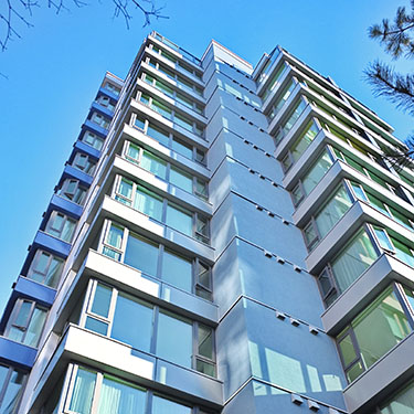
      A curtain wall is defined as thin, usually aluminum-framed wall, containing in-fills of glass, metal panels, or thin stone. The framing is attached to the building structure and does not carry the floor or roof loads of the building. The wind and gravity loads of the curtain wall are transferred to the building structure, typically at the floor line. Aluminum framed wall systems date back to the 1930's, and developed rapidly after World War II when the supply of aluminum became available for non-military use.

      Curtain wall systems range from manufacturer's standard catalog systems to specialized custom walls. Custom walls become cost competitive with standard systems as the wall area increases. This section incorporates comments about standard and custom systems. It is recommended that consultants be hired with an expertise in custom curtain wall design for projects that incorporate these systems.

      Description

      The following are brief descriptions of commonly used curtain wall framing methods and components.

      Curtain walls can be classified by their method of fabrication and installation into the following general categories: stick systems and unitized (also known as modular) systems. In the stick system, the curtain wall frame (mullions) and glass or opaque panels are installed and connected together piece by piece. In the unitized system, the curtain wall is composed of large units that are assembled and glazed in the factory, shipped to the site and erected on the building. Vertical and horizontal mullions of the modules mate together with the adjoining modules. Modules are generally constructed one story tall and one module wide but may incorporate multiple modules. Typical units are five to six feet wide.

      Curtain walls can also be classified as water managed or pressure-equalized systems. See Moisture Protection below.

      Both the unitized and stick-built systems are designed to be either interior or exterior glazed systems. Interior and exterior glazed systems offer different advantages and disadvantages. Interior glazed systems allow for glass or opaque panel installation into the curtain wall openings from the interior of the building. Details are not provided for interior glazed systems because air infiltration is a concern with interior glazed systems. Interior glazed systems are typically specified for applications with limited interior obstructions to allow adequate access to the interior of the curtain wall. For low rise construction with easy access to the building, outside glazing is typically specified. For high-rise construction interior glazing is sometimes used due to access and logistics of replacing glass from a swing stage.

      In exterior glazed systems, glass and opaque panels are installed from the exterior of the curtain wall. Exterior glazed systems require swing stage or scaffolding access to the exterior of the curtain wall for repair or replacement. Some curtain wall systems can be glazed from either the interior or exterior.

      Typical opaque panels include opacified spandrel glass, metal panels, thin stone, and other materials, such as terra cotta or FRP (fiber-reinforced plastic).

      Vision glass is predominantly insulating glass and may have one or both lites laminated (see Glazing), usually fixed but sometimes glazed into operable window frames that are incorporated into the curtain wall framing.

      Spandrel glass can be monolithic, laminated, or insulating glass. The spandrel glass can be made opaque through the use of opacifiers (film/paint or ceramic frit) applied on an unexposed surface or through "shadow box" construction, i.e., providing an enclosed space behind clear spandrel glass. Shadow box construction creates a perception of depth behind the spandrel glass that is sometimes desired.

      Metal panels can take various forms including aluminum plate, stainless steel or other non-corrosive metal, thin composite panels consisting of two thin aluminum sheets sandwiching a thin plastic interlayer, or panels consisting of metal sheets bonded to rigid insulation, with or without an inner metal sheet to create a sandwich panel.

      Thin stone panels are most commonly granite. White marble should not be used due to its susceptibility to deformation due to hysteresis (thin stone is not covered in this chapter).

      The curtain wall often comprises one part of a building's wall system. Careful integration with adjacent elements such as other wall claddings, roofs, and base of wall details is required for a successful installation.

      Fundamentals

      System Types

      Face-sealed, water-managed and pressure-equalized rainscreen systems are the three systems that are available. Normally, pressure-equalized rain screen systems provide the highest levels of resistance to air and water infiltration, with water-managed systems the next most reliable.

      Pressure-equalized rain screen systems function by blocking all of the forces that can drive water across a barrier. See the article on Moisture Protection for a complete explanation of how pressure-equalization resists water passage. As related to curtain wall systems, PE rain screen systems design the inside face of glass and the inside face of the glazing pocket and the interconnecting gasket or wet seal as an airtight barrier. The outside face of glass, exterior glazing materials and the outer exposed face of aluminum framing function as a rain screen, shedding water away. Between the exterior rain screen and the interior air barrier a pressure-equalization chamber is formed in the glazing pocket, which serves to reduce water penetration by eliminating (equalizing) the pressure difference across the rain screen that tends to force water into the system. Minor amounts of water that may penetrate the system are weeped harmlessly to the exterior.

      Water-managed systems appear similar at first glance, incorporating drains and weeps from the glazing pocket, but no effort is made to create an air barrier or "zone-glaze" each glass or spandrel unit, and therefore a larger amount of water is forced into the system and must be weeped away. Also, since no air barrier exists, the pressure differential between the glazing pocket and the interior may be strong enough to force water vertically higher than interior gaskets, resulting in leaks. Weep holes in a water-managed system function largely to drain water that enters the glazing pocket while weep holes in a pressure-equalized system function primarily as vents to allow air movement between the exterior and glazing pocket. Weeping of water is only a secondary function. Note that the easiest way to recognize a pressure-equalized rain screen system is yo note that the that glazing pocket around each individual unit of glass is isolated air tight from adjacent units, most obviously with plugs or seals at the gaps between screw splines at mullion intersections. Detailing of spandrels, shadow boxes and interface with adjacent construction must maintain the continuity of the air barrier and rainscreen to function properly with a pressure-equalized rainscreen curtain wall framing system.

      Some aluminum curtain wall systems are still designed as face-sealed barrier walls. They depend on continuous and perfect seals between the glass units and the frame and between all frame members to perform. The long-term reliability of such seals is extremely suspect and such systems should be avoided.

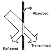
      Thermal Performance (Conduction, Solar Radiation, Thermal Break, Comfort)

      Overall curtain wall thermal performance is a function of the glazing infill panel, the frame, construction behind opaque (spandrel and column cover) areas, and the perimeter details.

      Curtain wall frame conductance is a function of the frame material, geometry and fabrication (e.g. thermal break).

      Aluminum has a very high thermal conductivity. It is common practice to incorporate thermal breaks of low conductivity materials, traditionally PVC, Neoprene rubber, polyurethane and more recently polyester-reinforced nylon, for improved thermal performance. Some "poured and debridged" polyurethane thermal breaks shrink and stress forms in the thermal break when the exterior aluminum moves differently from the interior aluminum due to temperature differences. Back-up mechanical attachment of the two halves of the frame is recommended (e.g. skip debridging or "t-in-a box"). A true thermal break is ¼" thick minimum and can be up to 1" or more, with the polyester reinforced nylon variety. Some curtain wall systems incorporate separators that are less than ¼", making them "thermally improved". The deeper thermal breaks can improve thermal performance and condensation resistance of the system.

      Some curtain wall systems utilize "pressure bars" (also referred to as "pressure plates") that are fastened to the outside of the mullions to retain the glass. These systems frequently include gaskets that are placed between the pressure bar and mullions and function as thermal breaks and help with acoustic isolation. These systems require special care in design and construction to ensure continuity of the gaskets at horizontal and vertical transitions. Gaskets are also used to cushion the glass on the interior and exterior faces of the glass. The problem with gaskets is that they tend to be stretched during installation and will shrink back to their original length in a short time; they will also shrink with age and exposure to ultraviolet radiation. There is usually a gap in the gasket at the corners after shrinkage occurs. With a properly designed system the water that enters the system at the gasket corners will weep out through the snap cover weep holes. To mitigate shrinkage of gaskets back from the corners the use of vulcanized corners and diagonally cut splices are recommended.

      Thermal performance of opaque areas of the curtain wall is a function of insulation and air/vapor barriers. Due to the lack of interior air adjacent to opaque curtain wall areas, these areas are subject to wide swings in temperature and humidity and require careful detailing of insulation and air/vapor barriers to minimize condensation. Some curtain wall systems include condensation drainage provisions, such as condensate gutters, that are intended to collect and weep condensate from spandrel areas to the exterior; such condensate gutters and weeps are a violation of the air barrier of the curtain wall unless they are outboard of the backpan. See discussion of back pans below.

      At the curtain wall perimeter, maintaining continuity of the air barrier reduces airflows around the curtain wall. Integration of perimeter flashings helps ensure watertight performance of the curtain wall and its connection to adjacent wall elements. Proper placement of insulation at the curtain wall perimeter reduces energy loss and potential condensation issues. Insulating the mullions in a spandrel area may lead to excessive condensation in cold climates unless it can also be assured that humid air from the interior will never come in contact with the mullions. The spandrel area is typically not heated, thus the interior environment does not warm the mullions and offset the migration of the cold temperatures deep into the wall. In the vision area the interior heat helps to mitigate the cold and prevents condensation. For this reason, do not insulate between the interior portion of mullions and adjacent wall construction either.

      Moisture Protection (Water Penetration, Condensation Resistance)

      Water penetration resistance is a function of glazing details (see Glazing), frame construction and drainage details, weatherstripping and frame gaskets, interior sealants (for operable windows, see Windows), and perimeter flashings and seals. Water can enter the exterior wall system by means of five different forces: gravity, kinetic energy, air pressure difference, surface tension, and capillary action. To mitigate water infiltration, all of these forces must be accounted for in the system design.

      Unlike discontinuous windows, which are smaller units and can rely to a high degree on sill flashings to capture frame corner leakage, curtain walls cover large expanses of wall without sill flashings at each glazed opening. Water penetration of curtain wall frame corners is likely to leak to the interior and/or onto insulating glass below. Watertight frame corner construction and good glazing pocket drainage are critical for reliable water penetration resistance.

      Visual (Daylighting, Aesthetics)

      Key visual features of curtain walls are glazing appearance (see Glazing) and sightlines. Sightlines are defined as the visual profile of the vertical and horizontal mullions. The sightlines are a function of both the width and depth of the curtain wall frame. Lateral load resistance requirements (wind loads, spans) generally dictate frame depth. Where narrow sightlines are desired, steel stiffeners inserted into the hollow frame of aluminum extrusions can help reduce frame depth.

      Sound (Acoustics)

      The acoustic performance of curtain walls is primarily a function of the glazing and internal seals to stop air leakage (covered elsewhere). The sound attenuation capability of curtain walls can be improved by installing sound attenuating infill and by making construction as airtight as possible. Incorporating different thicknesses of glass in an insulated glass unit will also help to mitigate exterior noise. This can be accomplished by increasing the thickness of one of the lites of glass or by incorporating a laminated layer of glass with a noise-reducing interlayer, typically a polyvinyl butyral or PVB.

      Back Pans

      Back pans are metal sheets, usually aluminum or galvanized steel, that are attached and sealed to the curtain wall framing around the perimeter behind opaque areas of a curtain wall. In cold climates insulation should be installed between the back pan and the exterior cladding in order to maintain the dew point outboard of the back pan so that the back pan acts as an air and vapor barrier. Back pans provide a second line of defense against water infiltration for areas of the curtain wall that are not visible from the interior and are difficult to access. Water infiltration in opaque areas can continue for extended periods of time causing significant damage before being detected. Back pans also are to be preferred over foil vapor retarders in high performance and humidified buildings as convection currents short-circuiting the insulation can cause condensation, wetting and ultimately failure of these spandrel areas.

      Shadow Boxes

      Shadow box construction creates the appearance of depth behind a transparent lite of glass by incorporating a metal sheet into the curtain wall behind the lite. The metal sheet should be at least two inches behind the glass and may be painted or formed to create a texture, but reflective surfaces add the most visual depth to the wall. Insulation should also be installed behind the shadow box if interior finishes prevent room air from contacting this area. The system should be designed to collect any condensation that may collect on the exterior side of the metal sheet and drain it back to the exterior. Shadow boxes present a variety of challenges related to venting the cavity behind the glass, that can allow dirt on surfaces difficult to clean, or sealing the cavity and risking excessive heat build-up. Either way, the cavity may be at temperatures significantly above or below interior conditions with only thermally conductive aluminum between them. This can lead to condensation or surfaces so hot they can burn. Careful detailing can provide a method to thermally isolate the cavity from the interior. An interior back pan behind the insulation is desirable as well, to avoid condensation on the metal shadow box from the interior.

      Support of Curtain Walls

      Curtain wall systems must transfer back to floor structure or intermediate framing both their own dead load plus any live loads, which consist primarily of positive and negative wind loads but might also include a snow load applied to large horizontal areas, seismic loads, maintenance loads and others. Unfortunately, the curtain wall will likely demonstrate movement caused by thermal changes and wind significantly different than movement of the building structure. Therefore the connections to anchor the curtain wall must be designed to allow differential movement while resisting the loads applied.

      In stick-framed aluminum curtain wall, vertical mullions commonly run past two floors, with a combined gravity/lateral anchor at one floor and a lateral anchor only at the other. The splice between the vertical mullions will also be designed to allow vertical movement while providing lateral resistance. In large areas of stick framed curtain wall, a split vertical mullion will be introduced periodically to allow thermal movement. Note that this movement slightly distorts the anchors at the vertical mullions. Individual units of glass must accommodate the movement of the surrounding aluminum frame by sliding along glazing gaskets, distorting the gaskets or a combination of both. The movement of the glass within the frame and the movement forced in the anchors tend to induce additional stresses into a stick framed system.

      Unitized curtain wall systems accommodate the differential movement between the structure and the thermal movement of the frame at the joints between each curtain wall unit. Because these units are frequently custom designed, the amount of movement to be accommodated can be carefully engineered into the system. Anchoring of unitized curtain wall typically consists of a proprietary assembly with three-way dimensional adjustability. The anchors occur at each pair of vertical mullions along the edge of slab or spandrel beam. Frequently, unitized systems span from a horizontal stack joint located at approximately desk height up to the anchor at the floor line above and then cantilevering past the floor to the next horizontal stack joint. The stack joint is designed to resist lateral loads while the two floor anchors resist gravity and lateral loads. One of the two floor anchors will allow movement in plane with the unitized system.

      Safety

      Fire Safety

      Fire safing and smoke seal at gaps between the floor slab-edge and the back of the curtain wall are essential to compartmentalize between floors and slow down the passage of fire and combustion gases between floors. A substantial ½" thick minimum poured smoke-seal is required to separate air return and supply plenums from each other, and for infection control in hospitals. Laboratory-tested fire rated assemblies may be required in unsprinklered buildings by some codes as Perimeter Fire Containment Systems when the floor assemblies are required to be fire-resistance rated. The ratings of the Perimeter Fire Containment System must be equal to or greater than the floor rating. These systems provide confidence that the materials used for perimeter containment remain in place for the specified duration of the required rating in a fire event.

      Fireman knock-out glazing panels are often required for venting and emergency access from the exterior. Knock-out panels are generally fully tempered glass to allow full fracturing of the panel into small pieces and relatively safe removal from the opening. Knock-out panels are identified by a non-removable reflective dot (typically two inches in diameter) located in the lower corner of the glass and visible from the ground by the fire department.

      Falling Ice and Snow

      Buildings in cold climates have struggled throughout the ages with ice and snow formations that slide, fall, or get windblown from their roofs, ledges, and window sills, causing harm to people and damage to property below. Refer to the Resource Page on Considerations for Building Design in Cold Climates.

      Maintenance Access

      The curtain wall should be designed for accessibility for maintenance. Low-rise buildings can generally be accessed from the ground using equipment with articulated arms. For high rise construction the building should be designed for swing stage access for window cleaning, general maintenance, and repair work, like glass replacement. Davits and fall arrest safety tieback anchors should be provided on the roof and stabilization tie-offs provided on the face of the wall to comply with OSHA standards CFR 1910.66, CFR 1910.28 and ANSI/IWCA I-14.1 "Window Cleaning Safety Standard".

      Health and Indoor Air Quality

      Curtain wall leakage, both air and water, can contribute to IAQ problems by supplying liquid water and condensation moisture for mold growth. This leakage can often remain concealed within the wall system and not become evident until concealed wall components experience significant deterioration and mold growth, requiring costly repairs.

      Durability and Service Life Expectancy

      Common curtain wall durability problems include the following:

      Glazing failures (see Glazing). Glazing problems specific to curtain wall construction include visual obstruction from condensation or dirt, damage to opacifier films from material degradation, condensation and/or heat build-up, and IGU issues/laminated glass issues.

      Failure of internal gaskets and sealants from curtain wall movements (thermal, structural), prolonged exposure to water (good drainage features reduce this risk), heat/sun/UV degradation (age). Repairs (if feasible) require significant disassembly of curtain wall. If restoration of internal seals is not physically possible or not economically feasible, installation of exterior surface wet sealing at all glazing and frame joints is often performed.

      Failure of exposed gaskets and sealants, including perimeter sealants, from curtain wall movements (thermal, structural), environmental degradation. Repairs require exterior access.

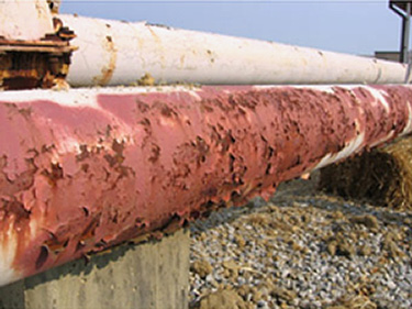
      Aluminum frames are inherently corrosion resistant in many environments if anodized and properly sealed or painted with baked-on fluoropolymer paint. Aluminum frames are subject to deterioration of the coating and corrosion of aluminum in severe (industrial, coastal) environments and galvanic corrosion from contact with dissimilar metals. Frame corner seals constructed using sealant are prone to debonding from prolonged contact with moisture and from thermal, structural, and transportation movements.

      Maintainability and Repairability

      Curtain walls and perimeter sealants require maintenance to maximize the service life of the curtain walls. Perimeter sealants, properly designed and installed, have a typical service life of 10 to 15 years although breaches are likely from day one. Removal and replacement of perimeter sealants requires meticulous surface preparation and proper detailing.

      Aluminum frames are generally painted or anodized. Factory applied fluoropolymer thermoset coatings have good resistance to environmental degradation and require only periodic cleaning. Recoating with an air-dry fluoropolymer coating is possible but requires special surface preparation and is not as durable as the baked-on original coating.

      Anodized aluminum frames cannot be "re-anodized" in place, but can be cleaned and protected by proprietary clear coatings to improve appearance and durability.

      Exposed glazing seals and gaskets require inspection and maintenance to minimize water penetration, limit exposure of frame seals, and protect insulating glass seals from wetting.

      Sustainability

      The best strategy for sustainability of curtain walls is to employ good design practices to ensure the durability (maximum service life) of the installation and to use systems that have a good thermal break and high R-value (values as high as R-7 are possible with triple-glazed systems). Also, the use of low-e and spectrally selective glass coatings can significantly reduce energy loads and improve comfort close to the wall.

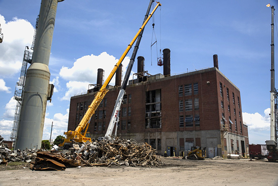
      Aluminum and steel frames are typically recycled at the end of their service life. Salvage and demolition contractors generally require a minimum of 1,000 sq ft or more of window/curtain wall to make material recycling economical (smaller amounts are generally disposed as general trash). Recycling is less economical if the aluminum is contaminated with sealants, fractured glazing, etc., as salvage companies pay considerably less for the material. There is a limited market for salvaged steel and wood frames.

      Applications

      Establish System Track Record

      Select a curtain wall with a demonstrated track record in similar applications and exposures. Verifying track records may require significant research by the designer. ASTM E1825 provides guidance.

      Review laboratory test results of systems or similar custom systems for air, water, and structural resistance, heat transmission, condensation resistance, sound transmission, and operability. Verify that tests pertain to the system under consideration and not a version of the system with the same product name but of different construction.

      Designing for Waterproofing Performance

      Curtain wall design should start with the assumption that external glazing seals, perimeter sealant joints and curtain wall sills will leak. The following summarizes recommended features:

      • Select frames with wept glazing and pocket sills sloped to the exterior to collect water that penetrates the glazing and drain it to the exterior. Do not use vertical mullions as drain conductors. Each glazing pocket should be fully isolated from adjacent glazing pockets. Provide a sill flashing with end dams and with an upturned back leg turned up into the glazing pocket at the base of the curtain wall to collect and drain curtain wall sill leakage; provide jamb flashings to direct perimeter leakage down to the sill flashing.
      • Key frame drainage features include slope to the exterior at surfaces that collect water (slope top of exposed horizontal mullion surfaces, slope at flashings), large (3/8 inch diameter or a slot 5/16" x 3/8" minimum) weep holes closely spaced (three weep holes per each section of horizontal mullion between vertical mullions, typically), and drainage at every horizontal frame (do not use vertical frames to drain past horizontal frames). Use as many 1/4-inch by 2-inch slots as required for pressure-equalized systems. Design the drainage system to handle condensation as well as rain.
      • Curtain wall perimeters should have flashings (sill, jambs and head) that are sealed to the air and water barrier at adjacent walls. Slope head and sill flashings to the exterior to promote drainage. Integrate curtain wall sill flashings with sill flashings or base of wall flashings of adjacent walls. Curtain wall should have a primary air/water seal between the shoulder of the tube at the plane of the glazing pocket and the air barrier of the adjacent construction.
      • Perimeter sealants are useful as a rainscreen for limiting air and water penetration through the outermost plane of the wall, but should not be relied upon as the sole air/water penetration barrier.
      • Coordinate placement of setting blocks with weep holes to avoid blocking drainage paths.

      Glazing Methods and Their Impact on Performance

      Pressure Plate Glazing: In this system the glass and infill panels are installed from the exterior, typically against dry gaskets. The outer layer of gaskets is installed and the gaskets are compressed against the glass by the torque applied to fasteners securing a continuous pressure plate. The plate is later typically covered with a snap-on mullion cover. This system provides reasonable performance but is susceptible to leaks at corners or joints in dry gaskets. For improved performance four-sided gaskets can be fabricated at additional cost or wet sealants can be installed to provide a concealed interior toe bead or exposed interior cap beads. Pressure plate glazing allows the easiest method to seal an air barrier from adjacent construction into the air barrier of curtain wall system.

      Interior Dry Glazing: In this system the glass and infill panels are installed from the interior of the building, eliminating the need for substantial scaffolding and saving money. The frame is fixed and exterior dry gaskets are installed. Typically only the top interior mullion has a removable stop. The glass unit is slid into a deep glazing pocket on one jamb far enough to allow clearing the opposite jamb and is then slid back into the opposite glazing pocket and then dropped into the sill glazing pocket. The removable interior stop is installed and finally an interior wedge gasket is forced in. Sometimes this method is called "jiggle" or "wiggle" glazing because of the manipulation necessary to get the glass into place. Performance is slightly reduced because dry metal to metal joints occur at the ends of the removable stop at a point that should properly be air and watertight. Wet sealant heel beads will improve performance and some systems include an extra gasket to form an air barrier seal. Installation of spandrel panels may need to be installed from the exterior.

      Structural Silicone Glazing: In this system the glass or infill unit is adhered to the frame with a bead of silicone. Outer silicone weather seals supplement the structural seal. Unitized systems are frequently structural silicone glazed, especially if four-side SSG is desired. Two-sided SSG, with pressure plate glazing or wiggle glazing on the other two sides is acceptable to be field installed.

      Butt-Glazing: SSG is frequently mistakenly referred to as butt-glazing. True butt-glazing has no mullion or other back-up member behind the joint and relies solely on a sealant, typically silicone, between the glass units to provide a perfect barrier seal.

      Designing for Condensation Resistance

      AAMA's Curtain Wall Design Guide provides guidance on window selection for condensation resistance. Establish the required Condensation Resistance Factor (CRF) based on anticipated interior humidity and local climate data and select a curtain wall with an appropriate CRF. Designers should be aware that the CRF is a weighted average number for a curtain wall assembly. The CRF does not give information about cold spots that could result in local condensation. Projects for which condensation control is a critical concern, such as high interior humidity buildings, require project-specific finite element analysis thermal modeling using software such as THERM. Careful analysis and modeling of interior conditions is required to accurately estimate the interior temperature of the air at the inside surfaces of the glass and frame. Curtain walls that are set well outboard of perimeter heating elements will have air temperatures along their interior surface that are significantly lower than the design wintertime interior temperatures. Thermal modeling of the building interior using Computational Fluid Dynamics (CFD) software can help establish a reasonable estimate for air temperatures at the inside surfaces of the glass and frame. These interior air temperatures are inputs for the thermal modeling software. Include lab mock-up thermal testing in addition to CFD modeling for analysis of project-specific conditions. Unusual or custom details, such as copings, deep sills, projected windows, spandrel areas and shadow box can dramatically alter performance.

      Use thermally broken or thermally improved aluminum frames for best performance. At the perimeter of the curtain wall, the thermal break must be properly positioned with respect to the wall system/insulation to avoid exposing the aluminum frame inboard of the thermal break to cold air ("short circuiting" the thermal break). Special insulation provisions may be required where curtain walls project beyond adjacent cladding systems (e.g., an insulated perimeter extrusion or metal panning).

      Consider frame geometry for thermally conductive aluminum frame materials. Minimize the proportion of framing exposed to the outdoors.

      Refer to AAMA 1503 for descriptions of test method, parameters and equipment for determining U factors and CRF's for window products. Refer to NFRC 100 for U Factor and NFRC 500 for condensation resistance.

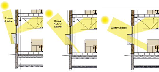
      Designing for Solar Heat Gain Control and Solar Optical Properties

      The use of glazed curtain walls can present challenges in balancing the desire for more natural daylight versus addressing the heat gain typically associated with such systems. Occasionally, there are concerns relating to having too much uncontrolled daylight, sometimes referred to as glare. The challenge is to strive for the highest visible light transmittance (VT) and the lowest solar heat gain coefficient (SHGC) while not preventing the glass from being too reflective when viewed from both the exterior and the interior, while controlling glare. This glass performance data are obtained from data using the Lawrence Berkeley National Laboratory (LBNL) Window 5.2 program with Environmental Conditions set at NFRC 100 criteria. NFRC 200 is used to determine the VT and SHGC values while the solar optical properties are determined using NFRC 300. Typically, for products more widely available on the market, the aforementioned values are readily available from glass manufacturers/fabricators.

      Designing for Finish Durability

      Aluminum: Class I anodic coatings (AAMA 611, supersedes AAMA 606, 607 and 608) and high performance factory applied fluoropolymer thermoset coatings (AAMA 2605) have good resistance to environmental degradation.

      Unitized Systems

      Unitized systems are typically custom designed. There isa wide range of systems on the market from manufacturers that provide varying levels of reliability. Unitized systems range in performance ability from industry standard to high performance walls. It is thus recommended that projects specifying unitized curtain wall systems incorporate a team member who has a breadth of experience in designing and working with unitized systems.

      Unitized systems are typically pressure equalized rain screen systems. The units should be completely assembled in a factory and shipped to the site for installation on the building. The units are placed on the floors, bundled in crates, using the tower crane and lowered into place using a smaller crane or hoist owned by the glazing contractor. The mullion dimensions tend to be slightly larger than a stick system due to their open section as compared to the tube shape of a standard stick curtain wall section. The advantages of the unitized system derive from the more reliable seals achievable from factory construction and the reduced cost of labor in the factory versus that of high rise field labor. Units can be assembled in a factory while the structural frame of the building is being constructed. Where stick systems require multiple steps to erect and seal the wall, unitized walls arrive on the site completely assembled allowing the floors to be closed in more quickly. Unitized systems also require less space on site for layout thus providing an advantage for urban sites with space limitations.

      Unitized systems generally rely on rain screen design principles and gaskets and/or the interlock of mating frames for moisture protection at joints between adjacent modules. The interlocking vertical mullions will typically have two interlocking legs. One leg will be in the plane just behind the glazing pocket and the other at the interior face of the mullions. The interlocking leg in the plane of the glazing pocket will be sealed by gaskets and is the primary line of defense against water and air infiltration. More robust systems will also include a gasket at the interior interlock. Systems whose connecting legs lock also compromise the ability of the system to accommodate movement. Some unitized designs are sensitive to small irregularities in the spacing of adjacent modules; for example, if the module joints are slightly out of tolerance, gaskets may not be properly compressed and moisture protection may suffer. Robust designs include multiple lines of defense, realistic tolerances and adjustability for erection of modules.

      The four-way intersection refers to the location where four adjacent units meet. This is where field labor must seal between adjacent units to achieve a weather tight wall. The interlocking legs of the horizontal mullions are the most critical interface of a unitized system. Water that infiltrates the interlocking vertical mullions drains to the interlocking horizontals that must collect and divert this water to the exterior. The top horizontal mullion of a unit incorporates upstanding vertical legs that mate with cavities in the bottom horizontal of the unit above. These upstanding legs have gaskets that seal against the walls of the bottom horizontal. Some designs provide one upstanding leg that provides one line of defense against air and water infiltration. More robust systems will provide two upstanding legs with gaskets on both legs. A splice plate or silicone flashing that is installed at the top of the two adjacent units as they are erected on the building is typically required.

      The vertical mullions of unitized systems typically anchor to the slab edge as they pass by. The stack joint is the horizontal joint where units from adjoining floors meet. Placing the stack joint at the sill of the vision glass (typically 30" above the floor) will minimize the dimension of the vertical mullions. This positioning utilizes the back span of the mullion above the anchoring point at the slab to counteract the deflection of the mullion below the slab. Also placing the stack joint above the floor provides a more convenient location for field workers to achieve the critical seal at the four-way intersection.

      While two story spans are feasible, the weight of the unit is doubled which may require increased structural capacity to accommodate the increased load. Wind load bracing should be incorporated at the single span height to avoid increasing the vertical mullion dimension to accommodate the increased span. Steel can be added to a unitized system to increase its spanning capability. However, unlike a stick system which has an integral hollow shape, the split mullions must be allowed to move independently to accommodate the building movement thus complicating the introduction of steel. Large units may also increase transportation costs from the factory to the site and erection costs of placing the units on the building.

      Thermally broken unitized systems are available, utilizing similar technology as that used in stick curtain wall systems.

      Logistical and Construction Administration Issues

      The service life of even the most durable curtain wall may be shorter than that of durable adjacent wall claddings such as stone or brick masonry. Therefore, the design of the curtain wall and perimeter construction should permit curtain wall removal and replacement without removing adjacent wall components that will remain.

      The service life expectancy of components that are mated with the curtain wall into an assembly should match the service life expectancy of the curtain wall itself. Require durable flashing materials, non-corroding attachment hardware and fasteners, and moisture resistant materials in regions subject to wetting.

      Laboratory testing: For projects with a significant amount of custom curtain wall, require laboratory testing of a mock-up curtain wall prior to finalizing project shop drawings. Have a curtain wall consultant present to document mock-up curtain wall construction and verify mock-up performance. Specify that laboratory tests are to be conducted at an AAMA Accredited Laboratory facility.

      Field Mock-up: For all curtain walls, stock or custom, require construction and testing of a field mock-up representative of the wall/window assembly. This is best scheduled prior to the release of shop drawings for window production, so that there is an opportunity to make design changes based on the test performance of the field mock-up. Specify that field tests be conducted by an independent third party agency accredited by AAMA.

      Field testing of curtain walls: Require the field testing of curtain walls for air infiltration and water penetration resistance, for quality assurance of curtain wall fabrication and installation. Require multiple tests with the first test on initial installations and later tests at approximately 35%, 70% and at final completion to catch problems early and to verify continued workmanship quality. Require additional testing to be performed if initial tests fail.

      Shop drawing coordination: Require curtain wall installation shop drawings showing all adjacent construction and related work, including flashings, attachments, interior finishes, and indicating sequencing of the work.

      Curtain wall systems, especially unitized systems, require expertise on the part of the building designer, the manufacturer, the fabricator, and the installer. For all but the simplest of systems, the designer should consider engaging an outside consultant, if such expertise is not available on the staff.

      Details

      The following details can be viewed online in Adobe Acrobat PDF by clicking on the PDF to the right of the drawing title.

      The details associated with this section of the BEDG on the WBDG were developed by committee and are intended solely as a means to illustrate general design and construction concepts only. Appropriate use and application of the concepts illustrated in these details will vary based on performance considerations and environmental conditions unique to each project and, therefore, do not represent the final opinion or recommendation of the author of each section or the committee members responsible for the development of the WBDG.

      Note: the following S-series details are courtesy of Richard Keleher Architect

      Typical Elevation—Stick-Built Curtain Wall-Pressure Equalized-Outside Glazed (Figure S – 1)   PDF

      This elevation shows a typical stick-built curtain wall set in a punched opening in a masonry cavity wall.

      • Elevation includes splice joints to accommodate thermal movement of the curtain wall frame.

      Curtain Wall Head—Stick-Built System-Pressure Equalized-Outside Glazed (Figure S – 2)   PDF

      • A through-wall metal flashing at the base of the brick cladding above the curtain wall protects the curtain wall from leakage through the wall above— (see Exterior Wall) for integration of the these components.
      • Locate exterior perimeter sealant joints behind trim cover to prevent water inside trim cover from bypassing the exterior sealant joint.

      Curtain Wall Jamb—Stick-Built System-Pressure Equalized-Outside Glazed (Figure S – 3)   PDF

      • Locate exterior perimeter sealant joints behind trim cover to prevent water inside trim cover from bypassing the exterior sealant joint.

      Curtain Wall Sill—Stick-Built System-Pressure Equalized-Outside Glazed (Figure S – 4)   PDF

      • Continuous metal sill flashing at the base of the curtain wall protects the wall framing below from leakage through the curtain wall. Sill flashing should have upturned end dams and fully sealed corners.

      Intermediate Mullion—Stick-Built System-Pressure Equalized-Outside Glazed (Figure S – 5)   PDF

      • Intermediate horizontal should be wept to the exterior and prevent water from draining onto the head of the glazing unit below. Care must be taken to ensure all corner frame joints in the glazing pocket are sealed to prevent leakage to the interior.
      • Locate setting blocks as to not obstruct water drainage from the glazing pocket.
      • Provide anti-walk blocks at the jambs of the glazing units. Blocks should be gapped 1/8-inch from the edge of the glazing unit.

      Isometric of Finished System—Stick-Built System-Pressure Equalized-Outside Glazed (Figure S – 6)   PDF

      Isometric of Curtain Wall Sill—Stick-Built System-Pressure Equalized-Outside Glazed (Figure S – 7)   PDF

      Isometric of Vertical Curtain Wall Mullions—Stick-Built System-Pressure Equalized-Outside Glazed (Figure S – 8)   PDF

      Elevation of Horizontal Pressure Plate—Stick-Built System-Pressure Equalized-Outside Glazed (Figure S – 9)   PDF

      Note: the following U-series details are courtesy of The Facade Group

      Isometric of System Assembly Unitized Curtain Wall System (Figure U–1)   PDF

      This elevation shows a typical unitized curtain wall assembly hung from the edge of the floor slab.

      • Differential movement between curtain wall units is accommodated at the vertical and horizontal unit joints.
      • The unit shown is composed of vision glazing and a glazed spandrel shadow box with an insulated back pan.

      Isometric of Open Stack Joint Unitized Curtain Wall System (Figure U–2)   PDF

      • A continuous vertical gasket provides the primary weather seal at the pressure equalized rainscreen zone of the assembly.
      • Foam glazing tape weather seal is discontinuous at horizontal panel joints to achieve pressure equalization between weather and air seals at vertical unit joints.
      • A splice cover is applied over the horizontal stack joint between units to provide continuous waterproofing behind and below the pressure equalized wet zone of the vertical stack joint.
      • The units are connected with a field applied splice sleeve that contains an index clip to align the next unit above the joint horizontally as it is being set.

      Isometric of Completed Stack Joint Unitized Curtain Wall System (Figure U–3)   PDF

      • Glazing pocket weeps are protected from wind-driven rain and pressure by a glazing trim cover containing weep slots in the bottom which are offset from the sill glazing pocket weep slots and the glazing setting blocks at glazing panel quarter points.
      • The primary air and water seal at the stack joint should have sufficient height and drainage to prevent water head from overtopping the gaskets. Gasket height should correspond to the curtain wall design pressure.
      • Exterior cover splice sleeves are installed at the face of the stack joint during unit field installation.

      Vision Glass Jamb Unitized Curtain Wall (Figure U–4)   PDF

      • Units are designed and installed with horizontal and vertical clearance gaps to allow for differential movement and accommodate construction tolerances.
      • Pressure equalized rainscreen gaskets form a primary weather seal at the face of the unitized vertical stack joint in line with the horizontal rainscreen gasket at the unit sill below.

      Unit Stack Joint Unitized Curtain Wall (Figure U–5)   PDF

      • Single or double glazing can be used at the spandrel area which is backed by a finish metal panel to form a shadow box.
      • Spandrel glass adapters are used to reduce the depth of the glazing pocket to accommodate reduced profile of spandrel glass. Spandrel glass adapters should be fully bedded in sealant and integrated with glazing pocket corner seals to prevent water leakage from glazing pocket to building interior.
      • Unit dimension of mating head and sill extruded profiles allows for specified floor to floor deflection at the stack joint.

      Intermediate Horizontal Unitized Curtain Wall (Figure U–6)   PDF

      • Intermediate horizontal members provide for divisions between vision panels or between vision and opaque or spandrel panels.
      • Intermediate horizontals stop at the face of the vertical unit jamb members at each end.

      Jamb at Spandrel Area with Anchorage to Slab Unitized Curtain Wall (Figure U–7)    PDF

      • Units are hung from the top or face of the adjacent floor or building structure using mated brackets and field applied bolts with a minimum of clearance for access and assembly.
      • All connections and brackets located within the units insulated or primary weather seal zones are sealed with appropriate sealant materials during field installation.

      Unit Anchor to Slab Edge Section Unitized Curtain Wall (Figure U–8)   PDF

      • Floor and ceiling closure is provided for fire and acoustical separation using code approved assemblies.

      Emerging Issues

      "Smart" Curtain Walls, like smart windows, control visible light transmittance by employing electrochromic or photochromic glass coatings; see the discussion in Glazing. Double-skin systems, which employ a ventilated space between the inner and outer walls are rare in the U.S., but have been constructed in Europe and Asia where energy costs are much higher. Similar in concept to air-flow windows, the ventilated space is intended to conserve energy by modulating the temperature conditions inboard of the curtain wall. During the heating season, the space acts as a buffer between the exterior and interior, and can be used to temper outdoor supply air. During the cooling season, warm interior air is exhausted into the space. There is currently discussion among building science experts that, at least for cold climates, a less expensive way of achieving energy savings might be through the use of curtain walls with high (over R-6) insulating values. Point-supported glass, structural glass mullions and use of tension structures are recent technologies.

      Relevant Codes and Standards

      Curtain Wall Design and Selection

      Thermal Performance

      Solar Heat Gain Coefficient

      Solar Optical Properties

      Air Infiltration

      Water Penetration Resistance

      Condensation Resistance Factor

      Seismic Loads

      • AAMA 501.4 & 501.6 Recommended Static Test Method for Evaluating Curtain Wall and Storefront Systems Subjected to Seismic and Wind Induced Interstory Drifts and Recommended Dynamic Test Method For Determining the Seismic Drift Causing Glass Fallout from a Wall System

      Structural Uniform Loading by Static Pressure

      Acoustical Performance

      Anodized Coatings

      High Performance Organic Coatings

      Additional Resources

      WBDG

      Design Objectives

      Functional / Operational—Ensure Appropriate Product/Systems Integration

      Products and Systems

      Building Envelope Design Guide—Glazing, Building Envelope Design Guide—Windows, See appropriate sections under applicable guide specifications: Unified Facility Guide Specifications (UFGS), VA Guide Specifications (UFGS), Federal Guide for Green Construction Specifications, MasterSpec®

      Organizations

      NOTE: Photographs, figures, and drawings were provided by the original author unless otherwise noted.

      Cybersecurity

      Introduction

      Industrial Control Systems (ICS) are physical equipment oriented technologies and systems that deal with the actual running of plants and equipment, include devices that ensure physical system integrity and meet technical constraints, and are event-driven and frequently real-time software applications or devices with embedded software. These types of specialized systems are pervasive throughout the infrastructure and are required to meet numerous and often conflicting safety, performance, security, reliability, and operational requirements. ICSs range from building environmental controls (HVAC, lighting), to systems such as the electrical power grid. With the increasing interconnectivity of ICS to the internet, the ICS can be an entry point into the organization's other IT systems.

      Within the controls systems industry, ICS systems are often referred to as Operational Technology (OT) systems. Historically, the majority of OT systems were proprietary, analog, vendor supported, and were not internet protocol (IP) enabled. Systems key components, such as Remote Terminal Units (RTUs), Programmable Logic Controllers (PLCs), Physical Access Control Systems (PACs), Intrusion Detection Systems (IDSs), closed circuit television (CCTV), fire alarm systems, and utility meters have become digital and IP enabled. OT systems use Human Machine Interfaces (HMIs) to monitor the processes, versus Graphical User Interfaces for IT systems. Most current ICS systems and subsystems are now a combination of Operational Technologies (OT) and Information Technologies (IT).

      The Stuxnet, Duqu, Flame and Shamoon malware were specifically designed to target ICS and cause physical damage to the processes or equipment. Stuxnet "spoofed" the integrity of the uranium centrifuges and caused the centrifuges to overspin and self-destruct, while the operators console showed the system was operating within normal parameters. The Duqu malware looks for information that could be useful in attacking industrial control systems. Its purpose is not to be destructive; the known components are trying to gather information. The Flame malware looks for engineering drawings, specifications, and other technical details about the systems and records audio, screenshots, keyboard activity, and network traffic. The program also records Skype conversations and can turn infected computers into Bluetooth beacons which attempt to download contact information from nearby Bluetooth-enabled devices. The Shamoon attack destroyed over 30,000 Saudi Armco work stations. Shamoon is capable of spreading to other computers on the network, through exploitation of shared hard drives. Once a system is infected, the virus continues to compile a list of files from specific locations on the system, erase and then send information about these files back to the attacker. Finally, the virus will overwrite the master boot record of the system to prevent it from booting as shown in Figure 1.

      screenshot of the Shamoon malware showing its ability to overwrite the master boot record of a computer

      Figure 1: The Shamoon malware has the ability to overwrite the master boot record of a computer. Image credit: Securelist

      In March 2018, the Department of Homeland Security issued Alert (TA18-074A) Russian Government Cyber Activity Targeting Energy and Other Critical Infrastructure Sectors.

      "This alert provides information on Russian government actions targeting U.S. Government entities as well as organizations in the energy, nuclear, commercial facilities, water, aviation, and critical manufacturing sectors. It also contains indicators of compromise (IOCs) and technical details on the tactics, techniques, and procedures (TTPs) used by Russian government cyber actors on compromised victim networks.

      This campaign comprises two distinct categories of victims: staging and intended targets. The initial victims are peripheral organizations such as trusted third-party suppliers with less secure networks, referred to as "staging targets" throughout this alert. The threat actors used the staging targets' networks as pivot points and malware repositories when targeting their final intended victims.

      In multiple instances, the threat actors accessed workstations and servers on a corporate network that contained data output from control systems within energy generation facilities. The threat actors accessed files pertaining to ICS or supervisory control and data acquisition (SCADA) systems."

      Figure 2 shows how DHS was able to reconstruct screenshot fragments of a Human Machine Interface (HMI) that the threat actors accessed.

      reconstructed screenshot fragments of a Human Machine Interface (HMI) that the threat actors accessed

      Figure 2: Reconstructed screenshot fragments of a Human Machine Interface (HMI) that the threat actors accessed. Photo Credit: www.us-cert.gov/ncas/alerts/TA18-074A

      In February 2013, Executive Order Improving Critical Infrastructure Cybersecurity was issued which requires the National Institute of Standards and Technology (NIST) to "lead the development of a framework to reduce cyber risks to critical infrastructure (the "Cybersecurity Framework"). The Cybersecurity Framework shall include a set of standards, methodologies, procedures, and processes that align policy, business, and technological approaches to address cyber risks. The Cybersecurity Framework shall incorporate voluntary consensus standards and industry best practices to the fullest extent possible.

      While federal agencies have been required to meet stringent Cybersecurity standards for the traditional IT systems since the Federal Information Security Management Act (FISMA) was passed in 2002, the same level of protection and analysis is just beginning to be developed for building control systems. Buildings are becoming increasingly reliant on technologies that allow centralized monitoring and control of multiple building systems ( Building Automation, Fire and Life Safety, Energy Management, Physical Security, Access Control, etc.), to assist in accomplishing design and operational goals. Because of the unique operating and configuration of building control systems, traditional IT processes such as continuous monitoring, host based scanning, and automated patch management can cause building control systems to fail or become non-operational.

      This section will provide an overview of the current efforts underway with regards to policy, standards, guides, and tools to assist building owners and operators, designers, and constructors meet the Cybersecurity challenges.

      Description

      Industrial Control Systems and Operational Technology

      Within the controls systems industry, Industrial Control Systems (ICS) are often referred to as Operational Technology (OT). ICS are physical equipment oriented technologies and systems that deal with the actual running of plants and equipment, include devices that ensure physical system integrity and meet technical constraints, and are event-driven and frequently real-time software applications or devices with embedded software. These types of specialized systems are pervasive throughout the infrastructure and are required to meet numerous and often conflicting safety, performance, security, reliability, and operational requirements.

      NIST SP 800-53 R4 defines ICS as:

      An information system used to control industrial processes such as manufacturing, product handling, production, and distribution. Industrial control systems include supervisory control and data acquisition (SCADA) systems used to control geographically dispersed assets, as well as distributed control systems (DCSs) and smaller control systems using programmable logic controllers to control localized processes.

      NIST SP 800-82 R2 further expands on the characteristics of ICS:

      Although some characteristics are similar, ICS also have characteristics that differ from traditional information processing systems. Many of these differences stem from the fact that logic executing in ICS has a direct effect on the physical world. Some of these characteristics include significant risk to the health and safety of human lives and serious damage to the environment, as well as serious financial issues such as production losses, negative impact to a nation's economy, and compromise of proprietary information. ICS have unique performance and reliability requirements and often use operating systems and applications that may be considered unconventional to typical IT personnel. Furthermore, the goals of safety and efficiency sometimes conflict with security in the design and operation of control systems.

      The term ICS is used in its broadest sense which includes:

      • Supervisory Control and Data Acquisition (Energy, Water, Wastewater, Pipeline, Airfield Lighting, Locks, and Dams, etc.)
      • Distributed Control Systems (Process and Manufacturing, etc.)
      • Building Control Systems/Building Automation Systems
      • Utility Management Control Systems
      • Electronic Security Systems
      • Fire, Life Safety, Emergency Management Systems
      • Exterior Lighting and Messaging Systems
      • Intelligent Transportation Systems

      Within the Department of Defense, there are over 30 unique types of ICS as shown in Figure 3. There are an estimated 2.5 million unique ICS systems that are used in over 300,000 buildings and over 250,000 linear structures.

      Examples of DoD OT and ICS systems and subsystems

      Figure 3: Examples of DoD OT and ICS Systems and Subsystems Courtesy of Fred E. Abbitt, CISSP-ISSEP, CSSA / Physical and Control System Security SME, Information Systems Engineering Command, Information Assurance and Security Engineering Directorate

      The majority of these systems were historically proprietary, analog, vendor supported, and used direct serial, and/or wireless connection, and were not IP enabled. The systems components such as Remote Terminal Units, Programmable Logic Controllers, Physical Access Control, Intrusion Detection Systems, CCTV, fire alarm systems, and utility meters have long equipment life spans, and are typically designated as Operational Technology (OT) and Real Property Equipment.

      ICSs differ significantly from traditional administrative, mission support and scientific data processing information systems, and use specialized software, hardware and protocols. ICS systems are often integrated with mainstream organizational information systems to promote connectivity, efficiency, and remote access capabilities. The "front end" portions of these ICSs resemble traditional information systems in that they use the same commercially available hardware and software components. While the majority of an ICS system still does not resemble a traditional information system (IS), the integration of the ICS's "front end" with IS introduces some of the same vulnerabilities that exist in current networked information systems.

      As these systems and components became digital and IP enabled, the interconnects to the organization network and business systems began to expose the organization to exploits and significant vulnerabilities. Typically, there was not a clear line of demarcation where one system started and one ended, for example a EMCS meter could be on the utility SCADA system, or on the buildings BAS. A comparison of IT versus OT systems is provided in the table below:

      Table 1—IT vs. OT Systems Comparison

       Information TechnologyOperational Technology
      PurposeProcess transactions, provide informationControl or monitor physical processes and equipment
      ArchitectureEnterprise wide infrastructure and applications (generic)Event-driven, real-time, embedded hardware and software (custom)
      InterfacesGUI, Web browser, terminal and keyboardElectromechanical, sensors, actuators, coded displays, hand-held devices
      OwnershipCIO and ITEngineers, technicians, operators and managers
      ConnectivityCorporate network, IP-basedControl networks, hard wired twisted pair and IP-based
      RoleSupports peopleControls machines

      ICSs can have long life spans (in excess of 20 years) and be comprised of technology that while functional, do not have the same technology refresh cycle as the IT. This introduces two issues: first, depending upon the relative age and isolation of the system, there may not be a patch or upgrade path for components of the system, and second, attempting to patch the component or employing modern scanning methods might disrupt the system. ICSs have experienced complete system shutdown when an intrusion detection system (IDS) or host-based scanning system (HBSS) scan is performed on an otherwise operational ICS. For an ICS, updates should be delayed until after a thorough analysis of deployment impact has been completed. This might stretch out security update timeliness and require flexibility in security control compliance measurement and enforcement.

      An ICS physical system can span many miles; for example, locks and dams, pipelines, electric transmission and distribution systems can have many non-contiguous components, and there are a number of protocols commonly used by ICSs to allow the devices to communicate both horizontally and vertically. A building use could use a number of protocols at the same time. Typical building protocols are:

      • LonWorks
      • BACnet
      • Modbus
      • DNP 3
      • Fox

      These protocols were developed initially to ensure availability and reliability, and able to communicate down to the device level with small data transmission and verification. Many devices have embedded firmware with default passwords. The protocol organizations and vendors are now working to add additional security features on new systems while working on securing legacy systems.

      Buildings can have a number of primary and secondary systems used to support the tenants and/or primary function of the building (office, hospital, warehouse, school, etc.).

      Communications Network and Business Systems

      The Communications Network and Business Systems include the Demarcation or Point of Entry where the external communications connect with the buildings internal network and include voice, data, video and multimedia information services, such as video conferencing and email. Typically the business systems are on a separate fiber high-speed backbone.

      Building Management System (BMS)

      The Building Management System provides automatic monitoring, interaction and management for electricity, ventilation, water supply, security and fire control to the building. A BMS typically manages the: Building Automation System (BAS), Electronic Security System (ESS), and the Fire and Life Safety System (FLS). For larger buildings and campuses, there will usually be a Building Operations Center (BOC), Security Operations Center (SOC), or Emergency Operations Center (EOC) that has engineering, O&M, security or emergency management personnel monitoring the BMS. In smaller buildings, there may only be a workstation and panels that alarm and report to an off-site BOC, SOC, or EOC.

      Building Automation System (BAS)/Building Control System (BCS)

      A building automation system (BAS) or Building Control Systems (BCS) is an example of a distributed control system. The control system is a computerized, intelligent network of electronic devices designed to monitor and control the mechanical, electronic, and lighting systems in a building. A building controlled by a BAS is often referred to as an Intelligent Building or a Smart Building.1

      BAS core functionality keeps the building climate within a specified range, provides lighting based on an occupancy schedule, monitors system performance and device failures, and provides malfunction alarms (via email and/or text notifications) to building engineering/maintenance staff. The BAS functionality reduces building energy and maintenance costs when compared to a non-controlled building. The BAS typically consists of:

      • Fire and Life and Safety (FLS)
      • Physical Security and Access Control (PACS)
      • Energy Management Systems (EMS), which includes Lighting Control
      • Heating, Ventilation and Air Conditioning (HVAC)

      A typical BAS architecture with multiple protocols is shown in Figure 4.

      Typical BAS architecture with a Primary Bus Network linking to two secondary Bus Networks

      Figure 4: Typical BAS Architecture

      Electronic Security System (ESSS)

      The Electronic Security System (ESS) is critical for providing a secure environment and protecting the safety of tenants. Elements include: Anti-theft Security and Alarm System, Electronic Control System, Physical Access Control System, Closed-Circuit TV Surveillance System. The ESS is typically monitored by security personnel in the SOC.

      Fire and Life Safety System (FLS)

      The Fire and Life Safety (FLS) system consists of the fire alarms, sensors, sprinklers, smoke purge, and exhaust fans, and is often connected to the BAS to shutdown HVAC, elevators, and other equipment. The FLS typically connects to the local fire department and alarms in the SOC and BOC. Traditionally, these systems were in separate conduits and cabling went from the control panel to the devices.

      Power over Ethernet

      A new technology, Power over Ethernet (PoE)2, is changing the traditional cabling process and operations of the BMS. PoE describes any of several standardized or ad-hoc systems which pass electrical power along with data on Ethernet cabling. This allows a single cable to provide both data connection and electrical power to devices such as network hubs or closed-circuit TV cameras. Unlike standards such as Universal Serial Bus which also power devices over the data cables, PoE allows long cable lengths. Power may be carried on the same conductors as the data, or it may be carried on spare pairs of the cable. A BAS with PoE is shown in Figure 5.

      Infographic titled Raising BACNet to the Next LevelA and depicting a BAS using power over ethernet

      Figure 5: A BAS using Power over Ethernet Credit: Contemporary Controls3

      There are a number of new PoE devices and systems that are entering the market and addressing the cybersecurity of these systems will be a challenge. When legacy systems are being modernized and/or upgraded with PoE, understanding the network connections and ripple effects of loss of communications or power must be carefully analyzed as part of the Contingency Plan and Disaster Recovery/Business Continuity Plan.

      Smart Buildings/Intelligent Buildings

      A Smart Building or Intelligent Building project generally covers three key elements.4

      • Communications Network and Office Automation
      • Building Management System
      • Integrated Services Infrastructure

      The GSA Public Building Service (PBS) has been an active leader in the development of Smart Buildings. In March 2011, the PBS issued the Technology Policy for PBS-Owned Building Monitoring and Control Systems memo, with the objective to "converge the building's Monitoring and Control (M&C) systems infrastructure to enable smarter and more efficient operations." The GSA Smart Building concept is shown in Figure 6.

      GSA Smart Buildings Concept showing the flow between buildings, people, and technology with GSA Building Link in the cneter

      Figure 6: GSA Smart Buildings Concept

      The GSA Smart Buildings effort had three broad objectives:

      1. Open Communication Protocols—Non-proprietary building controls that give GSA greater building management flexibility and reduce service costs

      2. Converged Control Systems Networks (IT backbone)—Elimination of unnecessarily redundant controls infrastructure such as conduit, cables, switches, and UPS's that will then allow interoperability and security compliance

      3. Normalized Data for Systems Communications—Different controls manufacturers or even disparate systems can "talk" to each other allowing for data collection and analysis and more flexibility and management control

      The resulting efforts are the convergence of the IT and OT into a new hybrid where the CIO provides the switches, routers and firewalls as Government Furnished Equipment (GFE), and all the building monitoring and control systems plug into the CIO fiber backbone in the distribution closet, as shown in Figure 7.

      Info graph with two boxes, the left is labeled Silos and shows straight lines for systems-HVAC, PAC, Video Surveillance, Digital Signage, Elevator, Advanced Metering, and Lighting. The right is labeled Converged and shows a WAN network in the center with those same systems-save sub-meters instead of advanced metering-branching off of it.

      Figure 7: Converged Building M&C Connected in the Distribution Closet

      While the GSA Smart Buildings model may work for many organizations, many others may not want to have the ESS or FLS running on the same fiber as the BAS. The redundancy and operational impact of converged systems is still a relatively new area.

      To help evaluate system interdependencies, GSA has developed the Sustainable Facilities Tool. A sustainable building can operate more efficiently and cost less when the impacts of systems on each other are considered. The system bundling section can be leveraged to further understand whole building synergies and explore examples for ideas on what technologies might best be bundled together.

      Achieving the design and operational performance requires a substantial change in mindset and training across multiple disciplines, changes in acquisition and contract language, and changes in the buildings operations and maintenance. GSA has developed a revised delivery process and is in the process of updating the Public Building Services Facilities Standard 100. The new process is shown in Figure 8.

      Infograpic illustrating the GSA Smart Buildings Life Cycle Approach, divided ito three sections, Educate, Design/Build, and Install, Test, Validate

      Figure 8: GSA Smart Buildings Life Cycle Approach

      Smart buildings are now becoming the norm across the country, and as the buildings get ever smarter and interconnected with Smart Cars, Smart Cities, etc., they become vulnerable to outside attack and malware. As the IT and OT systems continue to converge, the need for new Cybersecurity skills and training for the facilities workforce will need to be developed.

      The Department of Homeland Security Interagency Security Committee has developed several publications for risk assessments, facility security levels, and converged IT and OT assets, with an emphasis on physical access control systems, intrusion detection systems, and CCTV systems.

      Cyber-Physical Systems and the Critical Infrastructure Cybersecurity Framework

      An emerging classification developed by the National Science Foundation and NIST is to classify the hybrid IT and OT as Cyber-Physical Systems (CPS), "Cyber-Physical Systems or "smart" systems are co-engineered interacting networks of physical and computational components. The Framework for Cyber-Physical Systems Release 1.0  was published May 2016.

      These systems will provide the foundation of our critical infrastructure, form the basis of emerging and future smart services, and improve our quality of life in many areas. Cyber-physical systems will bring advances in personalized health care, emergency response, traffic flow management, and electric power generation and delivery, as well as in many other areas now just being envisioned. Other phrases that you might hear when discussing these and related CPS technologies include:

      • Internet of Things (IoT)
      • Industrial Internet
      • Smart Cities
      • Smart Grid
      • "Smart" Anything (e.g., Cars, Buildings, Homes, Manufacturing, Hospitals, Appliances)

      Source: https://www.nist.gov/el/cyber-physical-systems

      CPS are defined as integrated, hybrid networks of cyber and engineered physical elements; co-designed and co-engineered to create adaptive and predictive systems, and respond in real time to enhance performance.5 CPS reflect the advances in technology, similar to the shift that occurred going from the Industrial Revolution/Physical Systems to the Internet Revolution/Cyber Systems, and now transitioning to Industrial Internet Revolution/Cyber Physical Systems as shown in Figures 9 and 10.

      CPS Timeline Contex-from 1700 to about 1950 marks Physical Systems and is named the Industrial Revolution, 1950 to 2000 marks Cyber Systems and is named the Internet Revolution, finally, 2000 and beyond marks Cyber Physical Systems and is named the Industrial Internet Revolution

      Figure 9: CPS Timeline Context Credit: NIST Shyam Sunder Industrial Internet Workshop, March 2013

      CPS are enabling a new generation of 'smart systems'. NIST has taken an active role and lead in defining the CPS and has held several workshops, resulting in several publications in early 2013:

      • National Institute of Standards and Technology (NIST) Executive Roundtable on Cyber-physical Systems
      • National Institute of Standards and Technology (NIST) Executive Roundtable on Cyber-physical Innovation
      • National Institute of Standards and Technology (NIST) Executive Roundtable on Cyber-physical Systems Strategic R&D
      • National Institute of Standards and Technology (NIST) Industrial Internet Workshop, The Industrial Internet and Cyber-Physical Systems: A Government Perspective
      Circular infographic with the label Cyber-Physical Systems at the center/core of the image and starting clockwise the following ideas are outside of and surround the core: Smarter Planet, Sustainable Cities, Machine to Machine, Internet of Things, Smart Systems, and Industrial Internet

      Figure 10: CPS Common Core Context Credit: NIST Shyam Sunder Industrial Internet Workshop, March 2013

      Essential CPS characteristics include:6

      • Cyber, engineered, and human elements as treated as integral components of a total system to create synergy and enable desired, emergent properties

      • Integration of deep physics-based and digital world models provides learning and predictive capabilities for decision support (e.g., diagnostics, prognostics) and autonomous function

      • Systems engineering-based open architecture and standards provide for modularity and composability for customization, systems of products, and complex or dynamic applications

      • Reciprocal feedback loops between computational and distributed sensing/actuation and monitoring/control elements enables adaptive multi-objective performance

      • Networked cyber components provide a basis for scalability, complexity management, and resilience

      A comparison of the CPS systems and impacts across various sectors are provided in Table 2.

      Table 2—Cyber-Physical Sector ContextWithin body use: 7

      Innovative Products or ApplicationsCyber-Physical SystemsImpacts
       
      Smart Manufacturing and Production
      Agile manufacturingIntelligent controlsEnhanced global competitiveness
      Supply chain connectivityProcess and assembly automationU.S.-based high tech manufacturing
       Robotics working safely with humansGreater efficiency, agility, and reliability
      Transportation and Mobility
      Autonomous or smart vehicles (surface, air, water, and space)Drive by wire vehicle systemsAccident prevention and congestion reduction (zero-fatality highways)
      Vehicle-to-vehicle and vehicle-to-infrastructure communicationPlug ins and smart carsGreater safety and convenience of travel
       Interactive traffic control systems 
       Next-generation air transport control 
      Energy
      Electricity systemsSmart electric power gridGreater reliability, security, and diversity of energy supply
      Renewable energy supplyPlug-in vehicle charging systemsIncreased energy efficiency
      Oil and gas productionSmart oil and gas distribution grid 
      Civil Infrastructure
      Bridges and damsActive monitoring and control systemMore safe, secure, and reliable infrastructure
      Municipal water and wastewater treatmentSmart grids for water and wastewaterAssurance of water quality and supply
       Early warning systemsAccident warning and prevention
      Healthcare
      Medical devicesWireless body area networksImproved outcomes and quality of life
      Personal care equipmentAssistive healthcare systemsCost-effective healthcare
      Disease diagnosis and preventionWearable sensors and implantable devicesTimely disease diagnosis and prevention
      Buildings and Structures
      High performance residential and commercial buildingsWhole building controlsIncreased building efficiency, comfort and convenience
      Net-zero energy buildingsSmart HVAC equipmentImproved occupant health and safety
      AppliancesBuilding automation systemsControl of indoor air quality
       Networked appliance systems 
      Defense
      Soldier equipmentSmart (precision-guided) weaponsIncreased warfighter effectiveness, security, and agility
      Weapons and weapons platformsWearable computing/sensing uniforms 
      Supply equipmentIntelligent, unmanned vehiclesDecreased exposure for human warfighters and greater capability for remote warfare
      Autonomous and smart underwater sensorsSupply chain and logistics systems 
      Emergency Response
      First responder equipmentDetection and surveillance systemsIncreased emergency responder effectiveness, safety, efficiency, and agility
      Communications equipmentResilient communications networksRapid ability to respond to natural and other disasters
      Fire-fighting equipmentIntegrated emergency response systems 

      NIST has developed a reference architecture shown in Figure 11 that:

      Graphic depicting CPS Referece Architecture: The Physical Environment shows 6 levels starting with Physical System, Sensor and Actuators are above that, then Control System(s), next is Data Analytics, above that is Medeling, Optimization and Simulation, with Business and User goals at the top level. On the right side are Interoperability, then Security, Cybersecurity, Physical, Safety and Resiliency, followed by Human System Interaction, Data and Data Services, and Networking and Communications

      Figure 11: CPS Reference Architecture

      • Provides a common lexicon and taxonomy that can apply across CPS
      • Shows a common architectural vision to help facilitate interoperability between components and systems
      • Enables creation of reusable CPS components and tools to measure and evaluate their performance
      • Promotes communication across diverse stakeholder community

      The use of the CPS terminology and reference architecture will continue to be an evolving area.

      National Institute of Standards and Technology Computer Security Resource Center

      The NIST Computer Security Division, Computer Security Resource Center is where the standards and publications are maintained. NIST 800-53 Recommended Security Controls for Federal Information Systems and Organizations, and NIST 800-82 Guide to Industrial Control Systems (ICS) Security are used by most federal agencies as the baseline to evaluate their systems. Both publications were updated and published in spring 2013.

      The STUXNET, FLAME, and other cyber attacks have shown how vulnerable the nation's ICS are. As the Smart Grid develops, enhanced security controls are being developed by NIST, to include the NISTIR 7628 Guidelines for Smart Grid Cyber Security, and the NIST Framework and Roadmap for Smart Grid Interoperability Standard, Release 2.0. Buildings that have Advanced Smart Metering and other web or wireless connections to the system should be secured and tested to ensure vulnerabilities are mitigated and risks minimized.

      NIST Global City Teams Challenge and NIST Cybersecurity for IoT Program

      The Global City Teams Challenge (GCTC) program is a collaborative platform for the development of smart cities and communities, led by National Institute of Standards and Technology, a bureau of U.S. Department of Commerce, in partnership with other U.S. federal agencies including U.S. Department of Homeland Security Science and Technology Directorate (DHS S&T), National Science Foundation, International Trade Administration, and National Telecommunications and Information Administration. It enables local governments, nonprofit organizations, academic institutions, technologists, and corporations from all over the world to form project teams, or "action clusters," and "SuperClusters," to work on groundbreaking Internet of Things (IoT) and Cyber-Physical Systems (CPS) applications within the city and community environment.

      NIST's Cybersecurity for the Internet of Things (IoT) program supports the development and application of standards, guidelines, and related tools to improve the cybersecurity of connected devices and the environments in which they are deployed. By collaborating with stakeholders across government, industry, international bodies, and academia, the program aims to cultivate trust and foster an environment that enables innovation on a global scale.

      Department of Homeland Security ICS-CERT

      The Department of Homeland Security Control Systems Security Program is part of the United States Computer Emergency Readiness Team (US-CERT) and provides tools, standards, training, and publications for ICS.

      The Industrial Control Systems Cyber Emergency Response Team (ICS-CERT) works to reduce risks within and across all critical infrastructure sectors by partnering with law enforcement agencies and the intelligence community and coordinating efforts among Federal, state, local, and tribal governments and control systems owners, operators, and vendors. Additionally, ICS-CERT collaborates with international and private sector Computer Emergency Response Teams (CERTs) to share control systems-related security incidents and mitigation measures.

      Similar to the advancement of the number of malicious malware and hacking of traditional IT systems, critical infrastructure (CI) is now a primary target and the number of ICS-CERT reported incidents is exponentially increasing.

      Pie chart depicting vulnerablitilies by location in architecture

      Figure 12: ICS Vulnerabilities reported to ICS-CERT by ISA 99 Layer

      CSET is a desktop software tool that guides users through a step-by-step process to assess their control system and information technology network security practices against recognized industry standards. The output from CSET is a prioritized list of recommendations for improving the cybersecurity posture of the organization's enterprise and industrial control cyber systems. The tool derives the recommendations from a database of cybersecurity standards, guidelines, and practices. Each recommendation is linked to a set of actions that can be applied to enhance cybersecurity controls.

      Screen shot of the DHS Cyber Security Evaluation Tool

      Figure 13: DHS Cyber Security Evaluation Tool

      CSET has been designed for easy installation and use on a stand-alone laptop or workstation. It incorporates a variety of available standards from organizations such as National Institute of Standards and Technology (NIST), North American Electric Reliability Corporation (NERC), International Organization for Standardization (ISO), U.S. Department of Defense (DoD), and others. When the tool user selects one or more of the standards, CSET will open a set of questions to be answered. The answers to these questions will be compared against a selected security assurance level, and a detailed report will be generated to show areas for potential improvement.

      CSET provides an excellent means to perform a self-assessment of the security posture of your control system environment.

      GRASSMARLIN ICS Network Discovery Tool

      In support of a passive means to generate an Industrial Control System network and discover IP devices, NSA has developed the GRASSMARLIN (GM) tool. GRASSMARLIN is a software prototype that provides a method for discovering and cataloging SCADA (Supervisory Control and Data Acquisition) and ICS (Industrial Control System) systems on IP-based networks. GRASSMARLIN uses a variety of sources to generate this data, including PCAP files, router and switch configuration files, CAM tables and live network packet captures. The tool can automatically determine the available networks and generate the network topology as well as visualize the communication between hosts. GRASSMARLIN is still in a prototype phase.

      Grassmarlin has been approved for Open Source distribution. The executables and documentation can be accessed via the links below.

      Release Notes: https://github.com/iadgov/GRASSMARLIN
      Download: https://github.com/iadgov/GRASSMARLIN/releases/tag/v3.0.0

      The GM POC is Jerome Crocker

      A GM Plug-In has been integrated into the DHS ICS-CERT Cyber Security Evaluation Tool (CSET). When installing the tool, use Custom Install and select the GM Plug-In option. If you need assistance and/or technical support with CSET and GM Plug-In, contact Barry Hansen or Michael Chipley.

      Advanced Control System Tactics, Techniques, and Procedures (TTPs)

      USCYBERCOM developed the Advanced Control System Tactics, Techniques, and Procedures (TTPs)  that provide detailed step-by-step guidance to respond to a cyber attack. The starting point is to develop the Fully Mission-Capable (FMC) Baseline which consists of documentation that characterizes the control system such as the Topology diagram, Enclave entry points, User accounts, Server/workstation documentation, and Network documentation.

      The Recovery Jump-Kit contains the tools the control systems team and IT team will need to restore a system to its last FMC state during Mitigation and Recovery. Knowing what the Recovery point should be is the key to ensuring all known remnants of an attack have been removed from all components of the control system. In addition to containing the operating software for all devices, the Jump-Kit it also contains the software hashes of the devices on the network and the firmware and software updates for all system devices and checksums and hashes are in conformance with vendor specifications, and all hardware and software are configured in accordance with operational requirements. During Recovery, the Jump-Kit is utilized to reimage the firmware/software operating on the affected devices.

      Department of Homeland Security Science and Technology

      DHS S&T has developed several tools to assess the risk and resiliency of buildings, to include the cyber threat. The Integrated Rapid Visual Screening Tool, and the Owners Performance Requirement Tool assist building owners and operators evaluate the threats, vulnerabilities, and consequences and compare mitigation options.

      Committee for National Security Systems ICS Overlay

      The CNSS provides a forum for the discussion of policy issues, and is responsible for setting national-level Information Assurance policies, directives, instructions, operational procedures, guidance, and advisories for U.S. Government (USG) departments and agencies for the security of National Security Systems (NSS).

      In April 2012, DoD formed a Technical Working Group (TWG) and undertook the task of creating the first CNSSI 1253 ICS-PIT Overlay:

      "Security control overlays are specifications of security controls and supporting guidance used to complement the security control baselines and parameter values in the Committee on National Security Systems Instruction (CNSSI) No. 1253 and to complement the supplemental guidance in the NIST SP 800-53. Organizations select and apply CNSSI No. 1253 security control overlays by using the guidance in each of the standardized, approved and CNSS-published overlays."

      The TWG delivered the first ICS-PIT Overlay to the CNSS in January, 2013, after extensive collaboration among 65 representatives spanning DoD, DHS and numerous agencies. The Overlay is both a "primer," with a standard architecture and layers diagram, and a pictorial of typical devices, sensors and actuators that enable the I&E, IT and Information Assurance (IA) staff in the field to identify and understand the operational protocols (Modbus, LonTalk, etc.), network ports, and connections.

      CNSSI 1253 ICS Overlay Enclave Authorization Boundary and Layers

      Figure 14: CNSSI 1253 ICS Overlay Enclave Authorization Boundary and Layers

      The initial ICS-PIT Overlay was DoD-centric and used DoD specific parameters, and was issued as an informational and training document, and was included in the CSET 5.1 release. About the same time, working with the NIST SP 800-82R2 writing team, much of the material from the CNSSI ICS Overlay was incorporated into the update to 800-82, to include the new section 2.5 Other Types of Control Systems. With the release of NIST 800-53 R4 and NIST SP 800-82 R2, the CNSSI ICS Overlay is now obsolete and should not be used.

      Handbook for Self-Assessing Security Vulnerabilities & Risks of Industrial Control Systems on DoD Installations

      This handbook  was developed by the Air Force 346th Test Squadron, 262nd Network Warfare Squadron, Idaho National Laboratory and other stakeholder agencies in response to the need to address the lack of field guidance for ICS cybersecurity. The Department of Defense (DoD) Components and Agencies are encouraged to use this handbook to help establish a risk management framework to identify and prioritize mission-related vulnerabilities and risks that may be exposed or created by network connectivity to Industrial Control Systems (ICS). Installations & Environment (I&E)-related ICS include computer hardware, software, and associated sensors and controllers used to monitor and/or control real property, such as on-installation electricity, water, wastewater, natural gas, airfield lighting and petroleum systems. It also includes building heating and air conditioning equipment, lighting, fire and life safety systems. Supervisory Control and Data Acquisition Systems (SCADA), Distributed Control Systems (DCS), Energy Management Control Systems (EMCS) are also types of ICS.

      Footprinting/Discovery

      There are many tools and methods that can be used to identify building control systems that are exposed on the internet. One of the most powerful is Shodan. Figure 15 illustrates a search for Tridium which shows the IP address, protocol, organization, location, application software, firmware and other details. Figure 16 illustrates a search for Distech, which shows the building controller connecting through the Tridium servers and also displays the devices ID's, operating system, MD5 Hash, and Host ID's.

      Screenshot of the Shodan program displaying the search results for Tridium products

      Figure 15: Shodan Search Results for Tridium Products


      Screenshot of the Shodan program displaying search results for Distech products

      Figure 16: Shodan Search Results for Distech Products

      In the majority of these cases, clicking on the IP will open the login to the operator console as shown in Figure 17. In many cases, the browser is using an unencrypted http port 80, rather than encrypted https port 443, meaning the login credentials are being sent as open text across the internet. Organizations should not expose their Building Control Systems to direct internet connections; they should be in a DMZ, separated from the IT systems, and require a VPN connection.

      Screenshot of login for direct internet connection to Johnson Control Facility Explorer

      Figure 17: Direct Internet Connection to Johnson Controls Facility Explorer Login

      Other tools include Wireshark, NSA GrassMarlin, SamuraiSTFU, Kali Linux, NexDefense Sophia, GlassWire, Snort, Gleg, and Digital Bond Bandolier.

      Additional Resources

      Federal Agencies With Control Systems Responsibilities or Capabilities

      Control System Cyber Threats

      Publications

      General Industry IT and OT Tools

      Building and Control System Vendors/Products

      Websites

      Protocols

      Automation protocols
      Process automation
      Industrial control system
      Building Automation
      Power system automation
      Automatic meter reading
      Automobile / Vehicle

      Training Courses

      Workshops

      • "Cybersecurity of Buildings Workshop" – Jan. 28, 2014
        Focus was on the recently released draft DHS ISC Converged Systems White Paper document, GSA Smart Buildings program, and the NIST SP 800-82 Guide to Industrial Control Systems Security. This workshop built on the Cybersecurity of Building track listed below. The purpose of the Workshop was to bring the engineering, security, IT and IA communities together to build on current initiatives to create a common architecture and joint publications to develop defense in depth, continuous monitoring, incident response and recovery, and information sharing CONOPS for ICS and Converged Systems. Download materials and presentations
      • "Cybersecurity of Buildings Workshop: OT and IT Convergence—A New Paradigm". Building Innovation 2014: The National Institute of Building Sciences Annual Conference & Expo – Jan. 6, 2014.
      • "Cybersecuring Facilities and Facilities Systems". National Academy of Sciences (NAS) Federal Facilities Council (FFC) – May 2015.

      Footnotes

      1 [http://en.wikipedia.org/wiki/Building_automation]

      2 [http://en.wikipedia.org/wiki/Power_over_Ethernet]

      3 [Raising BACnet® to the Next Level, Connecting BACnet Devices to an IP Infrastructure ]

      4 [xinca.com/ elements-intelligent-buildings- 2734. html]

      5 [Key metrics include: efficiency and sustainability, agility and flexibility, reliability and resilience, safety and security.]

      6 [National Institute of Standards and Technology (NIST) Executive Roundtable on Cyber-physical Systems]

      7 [NIST Shyam Sunder Industrial Internet Workshop, March 2013]

      DAFMAN 32-1084 Facility Requirements Standards

      Summary

      Click on the “Facility Class” titles for subordinate standard documents by Category Group, then by Category Code. Authority for these standards is derived from AFI 32-1024 and DAFMAN 32-1084. They provide guidance for determining space allocations for Air Force facilities and may be used to program new facilities or evaluate existing spaces.

      Download the AF CATCode Spreadsheet for a complete list of all CATCodes.

      Questions, comments, suggestions and recommended changes for these documents are welcome and should be emailed to: FSM@us.af.mil

      These documents are available in the following formats:  Adobe Acrobat Portfolio (PDF) |  Microsoft Excel (XLSX)

      NOTE: The documents labeled "Complete Portfolio Set" are multiple Adobe Acrobat files compiled into a portfolio. Please download to your computer for optimal viewing.

      Title

      Date

      View

      DAFMAN GM 32-1084 Standard Facility Requirements

      11-28-2023

      PDF

      Supporting Documents

      Title

      Date

      View

      CatCode Listing

      04-01-2025

      XLSX

      Medical Group

      10-01-2020

      XLSX

      Mission Support Group

      10-01-2020

      XLSX

      Operations Group

      10-01-2020

      XLSX

      Maintenance Group

      10-01-2020

      XLSX

      Facility Planning Considerations

      04-01-2018

      PDF

      Common Administrative CATCODES

      10-01-2020

      XLSX

      Administrative and Administration Support Spaces Quick Lookup Guide

      04-01-2025

      XLSX

      FACILITY CLASS 1 – OPERATION AND TRAINING

      Category Group 11 – Airfield Pavements

      Title

      Date

      View

      AFRS Category Group 11 — Complete Portfolio Set

      04-01-2018

      PDF

      Category Group 11 — Airfield Pavements Overview

      04-01-2018

      PDF

      CC 111111 Runway

      07-01-2020

      PDF

      CC 111115 Overrun Paved

      07-01-2020

      PDF

      CC 111411 Runway Unpaved

      07-01-2020

      PDF

      CC 112211 Taxiway

      04-01-2018

      PDF

      CC 113321 Apron

      07-01-2020

      PDF

      CC 116116 Short Field Takeoff and Landing Zone

      07-01-2020

      PDF

      CC 116401 Precision Approach Radar Pad

      04-10-2023

      PDF

      CC 116402 Pad Fire and Rescue Vehicle

      07-01-2020

      PDF

      CC 116642 Shoulder Paved

      07-01-2020

      PDF

      CC 116661 Pad Arm and Disarm

      07-01-2020

      PDF

      CC 116662 Pad Dangerous Cargo Load Unload

      07-01-2020

      PDF

      CC 116663 Pad Helicopter

      07-01-2020

      PDF

      CC 116664 Pad Power Check

      07-01-2020

      PDF

      CC 116665 Pad Power Check with Noise Suppressor

      07-01-2020

      PDF

      CC 116666 Pad Warm up Holding

      07-01-2020

      PDF

      CC 116667 Pad Compass Calibration

      04-01-2018

      PDF

      CC 116668 Pad Launching

      07-01-2020

      PDF

      CC 116672 Aircraft Washrack Pad

      07-01-2020

      PDF

      CC 852269 Vehicle Parking Refueling

      07-01-2020

      PDF

      CC 852273 Aircraft Support Equipment Storage Yard

      07-01-2020

      PDF

      Category Group 12 – Liquid Fueling and Dispensing Facilities

      Title

      Date

      View

      AFRS Category Group 12 — Complete Portfolio Set

      11-09-2022

      PDF

      Category Group 12 — Liquid Fueling and Dispensing Facilities Overview

      04-01-2018

      PDF

      CC 121111 Petroleum Operations Building

      11-09-2022

      PDF

      CC 121115 Aviation Fuel Dispensing System

      04-01-2018

      PDF

      CC 121122 Hydrant Fueling System

      04-01-2018

      PDF

      CC 121124 Hydrant Fueling Building

      04-01-2018

      PDF

      CC 122111 Marine Fuel Dispensing Sys

      04-01-2018

      PDF

      CC 123335 Vehicle Fueling Station

      04-01-2018

      PDF

      CC 124131 Operating Storage Aviation Gas

      04-01-2018

      PDF

      CC 124132 Operating Storage Aviation Lubricant

      04-01-2018

      PDF

      CC 124134 Operating Storage Diesel

      04-01-2018

      PDF

      CC 124135 Operating Storage Jet Fuel

      04-01-2018

      PDF

      CC 124137 Operating Storage Motor Gas

      04-01-2018

      PDF

      CC 124138 Operating Storage Solvents

      04-01-2018

      PDF

      CC 124139 Operating Storage Special Fuels

      04-01-2018

      PDF

      CC 124340 Operating Storage E 85 Ethanol

      04-01-2018

      PDF

      CC 124341 Operating Storage Bio Diesel

      04-01-2018

      PDF

      CC 124342 Operating Storage Diesel JP 8

      04-01-2018

      PDF

      CC 125210 POL Piping System Within a Site

      04-01-2018

      PDF

      CC 125554 Pipeline Liquid Fuels

      04-01-2018

      PDF

      CC 125977 Pump Station Liquid Fuels

      04-01-2018

      PDF

      CC 126925 Liquid Fuel Truck Fill Stand

      04-01-2018

      PDF

      CC 126926 Liquid Fuel Stand Unloading

      04-01-2018

      PDF

      CC 130142 Fire Crash Rescue Station

      04-01-2018

      PDF

      CC 821112 Heating Fuel Oil Storage

      04-01-2018

      PDF

      Category Group 13 – Communications, Navigation Aids and Airfield Lighting

      Title

      Date

      View

      AFRS Category Group 13 — Complete Portfolio Set

      09-01-2024

      PDF

      Category Group 13 — Communications, Navigation Aids and Airfield Lighting Overview

      04-01-2018

      PDF

      CC 131111 Communications Facility

      08-23-2024

      PDF

      CC 131114 Military Affiliate Radio System (MARS) Facility

      04-01-2018

      PDF

      CC 131115 Communications Receiver Facility

      04-01-2018

      PDF

      CC 131116 Communications Transmitter/Receiver Facility

      04-01-2018

      PDF

      CC 131117 Communications Transmitter Facility

      04-01-2018

      PDF

      CC 131118 Radio Relay Facility

      04-01-2018

      PDF

      CC 131132 Satellite Ground Communications Ground Terminal

      04-01-2018

      PDF

      CC 131133 Communications Scatter

      04-01-2018

      PDF

      CC 131134 Air Communications (AIRCOM) Relay Center Facility

      04-01-2018

      PDF

      CC 131135 Automatic Switching Center

      04-01-2018

      PDF

      CC 131136 AIRCOM Receiver Facility

      04-01-2018

      PDF

      CC 131137 AIRCOM Transmitter Facility

      04-01-2018

      PDF

      CC 131138 High Frequency AIRCOM Microwave Relay Facility

      04-01-2018

      PDF

      CC 131139 Microwave Repeater

      04-01-2018

      PDF

      CC 131143 Gap Filler

      04-01-2018

      PDF

      CC 131200 Space Operations Facility

      04-01-2018

      PDF

      CC 132131 SILO Hardened HF Antenna

      04-01-2018

      PDF

      CC 132134 Antenna Support Structure

      04-01-2018

      PDF

      CC 133101 Non-Directional Beacon (Building)

      04-01-2018

      PDF

      CC 133314 UHF Direction Finding

      04-01-2018

      PDF

      CC 134101 Wind Measuring Equipment

      04-01-2018

      PDF

      CC 134102 Automatic Meteorological Station

      04-01-2018

      PDF

      CC 134103 Runway Distance Markers

      04-01-2018

      PDF

      CC 134119 Remote Control Circuits

      04-01-2018

      PDF

      CC 134335 Ground Control Intercept

      04-01-2018

      PDF

      CC 134336 Fixed Radar Approach Control (RAPCON) (GCA Fixed) Facility

      04-01-2018

      PDF

      CC 134341 RAPCON Support Building (GCA/RAPCON Support Building)

      04-01-2018

      PDF

      CC 134351 Instrument Landing System (ILS) Glide Slope

      04-01-2018

      PDF

      CC 134353 ILS Localizer

      04-01-2018

      PDF

      CC 134355 ILS Marker Beacon

      04-01-2018

      PDF

      CC 134373 Radar Turntable

      04-01-2018

      PDF

      CC 134374 Precision Approach Radar

      04-01-2018

      PDF

      CC 134375 RAPCON Center

      04-01-2018

      PDF

      CC 134376 Airport Surveillance Radar

      04-01-2018

      PDF

      CC 134442 Radio Beacon Facility

      04-01-2018

      PDF

      CC 134465 TACAN Air Navigation Station

      04-01-2018

      PDF

      CC 134473 NAVAID Tower

      04-01-2018

      PDF

      CC 134482 Fixed VHF Omni Range Station

      04-01-2018

      PDF

      CC 134484 High Power VHF Omni Range

      04-01-2018

      PDF

      CC 134511 TVOR-RACAN, Fixed (VORTAC, Fixed)

      04-01-2018

      PDF

      CC 134678 Wind Direction Indicator

      04-01-2018

      PDF

      CC 135583 Telephone Duct Facility

      04-01-2018

      PDF

      CC 135586 Telephone Pole Facility

      04-01-2018

      PDF

      CC 136635 Beacon Light

      04-01-2018

      PDF

      CC 136661 Approach Lighting

      04-01-2018

      PDF

      CC 136662 Obstruction Lighting

      04-01-2018

      PDF

      CC 136664 Runway Lighting

      04-01-2018

      PDF

      CC 136666 Special Airfield Lighting

      04-01-2018

      PDF

      CC 136667 Taxiway Lighting

      04-01-2018

      PDF

      CC 141391 Radar Transmitter and Computer Building

      04-01-2018

      PDF

      CC 141762 Embedded Software Integration Facility

      04-01-2018

      PDF

      CC 149511 Remote Pilot Aircraft Operations

      04-10-2023

      PDF

      CC 149516 Aircraft Guidance Station

      04-01-2018

      PDF

      CC 149621 Wind Measuring Set

      04-01-2018

      PDF

      CC 149622 Ceilometer Rotating Beacon

      04-01-2018

      PDF

      CC 149623 Transmissometer

      04-01-2018

      PDF

      CC 149624 Temperature Dew Point Measuring Set

      04-01-2018

      PDF

      CC 149625 Digital Wind Measuring System

      04-01-2018

      PDF

      CC 149626 Lightning Warning System

      04-01-2018

      PDF

      CC 149627 Radar Meteorological Set

      04-01-2018

      PDF

      CC 740657 Master Television Antenna

      04-01-2018

      PDF

      Category Group 14 – Land Operational Facilities

      Title

      Date

      View

      AFRS Category Group 14 — Complete Portfolio Set

      08-23-2024

      PDF

      CC 116922 Aircraft Arresting Systems

      04-01-2018

      PDF

      CC 116933 Firing In Buttress

      04-01-2018

      PDF

      CC 116945 Jet Blast Deflector

      04-01-2018

      PDF

      CC 121111 Petroleum Operations Building

      04-01-2018

      PDF

      CC 121124 Hydrant Fueling Building

      04-01-2018

      PDF

      CC 130142 Fire Crash Rescue Station

      04-01-2018

      PDF

      CC 131119 American Forces Radio and Television Station

      04-01-2018

      PDF

      CC 140421 Emergency Operations Center

      08-23-2024

      PDF

      CC 140422 Sensitive Compartmented Information Facility (SCIF)

      04-01-2024

      PDF

      CC 141101 Airfield Fire Rescue Station

      04-01-2018

      PDF

      CC 141154 Crash Boat Crew Station

      04-01-2018

      PDF

      CC 141165 Explosive Ordnance Disposal

      04-01-2018

      PDF

      CC 141175 Guided Missile Launch Control

      04-01-2018

      PDF

      CC 141181 Aircraft Shelter

      04-01-2018

      PDF

      CC 141182 Hardened Aircraft Shelters

      04-01-2018

      PDF

      CC 141183 Alert Hangar Fighter Aircraft

      04-01-2018

      PDF

      CC 141185 Helicopter Rescue Recovery Hangar

      04-01-2018

      PDF

      CC 141387 Film Storage Vault

      04-01-2018

      PDF

      CC 141389 Television Production Facility

      04-01-2018

      PDF

      CC 141392 Radar Transmitter Building (BMEWS)

      04-01-2018

      PDF

      CC 141393 Scanner Building (BMEWS)

      04-01-2018

      PDF

      CC 141411 Radome Tower Building

      04-01-2018

      PDF

      CC 141421 Radar Tower Building

      04-01-2018

      PDF

      CC 141446 Combat Center Building

      04-10-2023

      PDF

      CC 141447 Direction Center Facility

      04-01-2018

      PDF

      CC 141449 Range Operations Headquarters

      04-10-2023

      PDF

      CC 141453 Base Operations (Airfield Management, Weather, etc.)

      04-01-2018

      PDF

      CC 141454 Tactical Operations

      04-10-2023

      PDF

      CC 141455 Ordnance Control Point

      11-09-2022

      PDF

      CC 141456 Intelligence Surveillance and Reconnaissance Squadrons

      04-10-2023

      PDF

      CC 141459 Readiness Crew

      11-09-2022

      PDF

      CC 141461 USAF Command Post

      04-01-2018

      PDF

      CC 141481 Aircraft Control and Warning Operations Dewline

      04-01-2018

      PDF

      CC 141489 Aircraft Control and Warning Operations Bldg

      04-01-2018

      PDF

      CC 141626 Weather RAWINSONDE Building

      04-01-2018

      PDF

      CC 141627 Weather Instrument Building

      04-01-2018

      PDF

      CC 141629 Surface Weather Observing Facility

      11-09-2022

      PDF

      CC 141635 Rocket Sonde Container Building

      04-01-2018

      PDF

      CC 141649 Weather Wing Headquarters

      04-10-2023

      PDF

      CC 141743 Base Photo Laboratory

      04-01-2018

      PDF

      CC 141745 Reconnaissance Photo Laboratory

      04-01-2018

      PDF

      CC 141747 Photo Processing and Interpretation Facility Support Building

      04-01-2018

      PDF

      CC 141753 Squadron Operations

      04-01-2018

      PDF

      CC 141763 Technical Laboratory

      04-01-2018

      PDF

      CC 141764 Integration Support Facility

      04-01-2018

      PDF

      CC 141765 Depot Quality Control Laboratory

      04-01-2018

      PDF

      CC 141766 Technical Laboratory Liquid Fuels Anaysis

      04-01-2018

      PDF

      CC 141782 Air Freight Terminal

      04-01-2018

      PDF

      CC 141783 Air Freight Passenger Terminal

      04-01-2018

      PDF

      CC 141784 Air Passenger Terminal

      11-09-2022

      PDF

      CC 141785 Fleet Service Terminal

      04-01-2018

      PDF

      CC 141786 Deployment Processing Facility

      11-09-2022

      PDF

      CC 141787 Consolidation Containerization Point

      04-01-2018

      PDF

      CC 141911 Missile Operations Building

      04-01-2018

      PDF

      CC 141912 Re-Entry Vehicle Building

      04-01-2018

      PDF

      CC 141914 Missile Guidance Facility

      04-01-2018

      PDF

      CC 141915 Missile Transfer Building

      04-01-2018

      PDF

      CC 143199 Ship Operations Building

      04-01-2018

      PDF

      CC 144321 Box Crate Shop

      04-01-2018

      PDF

      CC 144401 Vehicle Holding Building

      04-01-2018

      PDF

      CC 144421 Dispatch Building

      04-01-2018

      PDF

      CC 144422 Scale House

      04-01-2018

      PDF

      CC 144423 Safety Building

      04-01-2018

      PDF

      CC 145921 Overhead Protection

      04-01-2018

      PDF

      CC 146601 Aircraft Sunshelter

      04-01-2018

      PDF

      CC 149399 Explosives Railway Holding Yard

      04-01-2018

      PDF

      CC 149411 Bunker

      04-01-2018

      PDF

      CC 149511 Pilotless Guidance Station

      08-23-2024

      PDF

      CC 149512 Missile Launch Facility

      04-01-2018

      PDF

      CC 149514 Missile Guidance Station

      04-01-2018

      PDF

      CC 149628 Central Wash Facility

      04-01-2018

      PDF

      CC 149629 Cold Fog Dispersal System

      04-01-2018

      PDF

      CC 149711 Missile Shaft Access

      04-01-2018

      PDF

      CC 149721 Heavy Demolition Area

      04-01-2018

      PDF

      CC 149811 Tunnel

      04-01-2018

      PDF

      CC 149921 Vehicle Test Track

      04-01-2018

      PDF

      CC 149962 Air Traffic Control Tower

      11-09-2022

      PDF

      CC 149965 Radar Tower

      04-01-2018

      PDF

      CC 149968 Special Tower

      04-01-2018

      PDF

      CC 159353 Warehouse Transit Cargo

      04-01-2018

      PDF

      CC 171619 Runway Supervisory Unit Building

      04-01-2018

      PDF

      CC 171620 Runway Control Structure Building

      04-01-2018

      PDF

      CC 422275 Ancillary Explosives Facility

      04-01-2018

      PDF

      CC 610332 FARM Facility

      04-01-2018

      PDF

      CC 730145 Fire Observation Tower and Communication Center

      04-01-2018

      PDF

      CC 730834 Security Forces Defensive Fighting Position

      04-01-2018

      PDF

      CC 730836 Reserve Fire Team Facility

      11-09-2022

      PDF

      CC 730837 Security Police Entry Control Building

      11-09-2022

      PDF

      CC 730838 Master Surveillance Control Facility

      11-09-2022

      PDF

      CC 730839 Access Control Facility

      11-09-2022

      PDF

      CC 730841 Security Forces Military Working Dog Kennel

      11-09-2022

      PDF

      CC 730842 SF Kennel Support Facility

      11-09-2022

      PDF

      CC 872845 Security Guard Tower

      04-01-2018

      PDF

      CC 872911 Revetment Pre–Engineered

      04-01-2018

      PDF

      CC 890151 Tramway Aerial

      04-01-2018

      PDF

      Category Group 15 – Waterfront Operational Facilities

      Title

      Date

      View

      AFRS Category Group 15 — Complete Portfolio Set

      04-01-2018

      PDF

      CC 151153 Cargo Pier

      04-01-2018

      PDF

      CC 151155 Liquid Fuel Unloading Pier

      04-01-2018

      PDF

      CC 152111 Wharf

      04-01-2018

      PDF

      CC 154452 Waterfront Improvements

      04-01-2018

      PDF

      CC 155199 Small Craft Berthing

      04-01-2018

      PDF

      CC 213332 Boat Storage

      04-01-2018

      PDF

      Category Group 16 – Harbor and Coastal Operations

      Title

      Date

      View

      AFRS Category Group 16 — Complete Portfolio Set

      04-01-2018

      PDF

      CC 163311 Liquid Fuel Off Shore Unloading Facility

      04-01-2018

      PDF

      CC 164211 Harbor and Coastal Marine Improvements

      04-01-2018

      PDF

      Category Group 17 – Training Facilities

      Title

      Date

      View

      AFRS Category Group 17 — Complete Portfolio Set

      08-23-2024

      PDF

      Category Group 17 — Training Facilities Overview

      11-09-2022

      PDF

      CC 149967 Observation Tower

      04-01-2018

      PDF

      CC 171152 Academic Lecture Hall

      04-01-2018

      PDF

      CC 171157 Natatorium and Physical Education

      04-01-2018

      PDF

      CC 171158 Band Center

      08-23-2024

      PDF

      CC 171211 Flight Training Classroom

      04-01-2018

      PDF

      CC 171212 Flight Simulator Training

      11-09-2022

      PDF

      CC 171214 Physiological Training

      11-09-2022

      PDF

      CC 171250 Human Performance Training Center
      CC 171250 HPTC Space Allocation Calculator (xlsx)

      08-23-2024

      PDF

      CC 171356 Technical and Professional Library

      04-01-2018

      PDF

      CC 171393 Celestial and Planetarium Navigational Training

      04-01-2018

      PDF

      CC 171443 Reserve Forces General Training Support

      04-01-2018

      PDF

      CC 171445 Reserve Forces Operational Training

      04-01-2018

      PDF

      CC 171447 Reserve Forces Communications and Electronic Training

      04-01-2018

      PDF

      CC 171449 Reserve Forces Aeromedical Evacuation Training

      04-01-2018

      PDF

      CC 171450 Reserve Component Medical Training

      04-01-2018

      PDF

      CC 171471 Range Control House

      04-01-2018

      PDF

      CC 171472 Range Supplies and Equipment Storage

      04-01-2018

      PDF

      CC 171473 Range Target Storage and Repair

      11-09-2022

      PDF

      CC 171475 Indoor Small Arms Range

      04-01-2018

      PDF

      CC 171476 Combat Arms (CA)Building

      04-01-2018

      PDF

      CC 171617 Training Aids Shop

      04-01-2018

      PDF

      CC 171618 Field Training Facility

      04-01-2018

      PDF

      CC 171621 Technical Training Classroom

      04-01-2018

      PDF

      CC 171623 Technical Training Laboratory

      04-01-2018

      PDF

      CC 171625 High Bay Technical Training

      04-01-2018

      PDF

      CC 171627 Technical Training Support

      04-01-2018

      PDF

      CC 171628 Launch Operations Training Facility

      04-01-2018

      PDF

      CC 171712 Target Intelligence Training

      04-01-2018

      PDF

      CC 171721 Organizational Classroom

      04-01-2018

      PDF

      CC 171813 Safety Education Facility

      04-01-2018

      PDF

      CC 171815 Enlisted Professional Military Education (PME) Center

      04-01-2024

      PDF

      CC 171833 Basic Military Training

      04-01-2018

      PDF

      CC 171844 Officer Training

      04-01-2018

      PDF

      CC 171851 Air University Professional Technical Education

      04-01-2018

      PDF

      CC 171853 US Air Force Academy Academic Training

      04-01-2018

      PDF

      CC 171873 Aerial Port Training Facility

      04-01-2018

      PDF

      CC 171875 Weapons Munitions Load Crew Training

      11-09-2022

      PDF

      CC 172321 Gas Chamber

      04-01-2018

      PDF

      CC 172421 Simulator Building Non-Mot

      04-01-2018

      PDF

      CC 172423 Simulator Center

      04-01-2018

      PDF

      CC 172424 Battle Laboratory

      04-01-2018

      PDF

      CC 173321 Other Covered Training Area

      04-01-2018

      PDF

      CC 173421 Observation Tower Bunker

      04-01-2018

      PDF

      CC 174121 Land Navigational Course

      04-01-2018

      PDF

      CC 174122 Field Training Area

      04-01-2018

      PDF

      CC 174123 Maneuver Training Area Light Forces

      04-01-2018

      PDF

      CC 174221 Maneuver Training Area, Heavy Forces

      04-01-2018

      PDF

      CC 174321 Impact Area Non Dudded

      04-01-2018

      PDF

      CC 174322 Impact Area Dudded

      04-01-2018

      PDF

      CC 174499 Parachute Drop Zone

      04-01-2018

      PDF

      CC 174521 Parade Drill Field

      04-01-2018

      PDF

      CC 175121 Basic 10M 25M Firing Range

      04-01-2018

      PDF

      CC 175221 Automated Field Fire Range

      04-01-2018

      PDF

      CC 175321 Automated Record Fire Range

      04-01-2018

      PDF

      CC 175421 Night Fire Small Arms Range

      04-01-2018

      PDF

      CC 175422 Automated Night Fire Small Arms Range

      04-01-2018

      PDF

      CC 175521 Known Distance (KD) Range

      04-01-2018

      PDF

      CC 175621 Sniper Field Fire Range

      04-01-2018

      PDF

      CC 175622 Automated Sniper Field Fire Range

      04-01-2018

      PDF

      CC 175721 Combat Pistol/MP Firearms Qualification Course

      04-01-2018

      PDF

      CC 175821 Machine Gun Field Fire Range

      04-01-2018

      PDF

      CC 176221 40MM Grenade Machine Gun Qualification Range

      04-01-2018

      PDF

      CC 176321 Light Antiarmor Weapons (LAW/AT-4) Range Sub Caliber

      04-01-2018

      PDF

      CC 176322 Light Antiarmor Weapons Range

      04-01-2018

      PDF

      CC 176521 Field Artilery Direct Fire Range

      04-01-2018

      PDF

      CC 176621 Tank Fighting Vehicle Gunnery Range

      04-01-2018

      PDF

      CC 176721 Mortar Range

      04-01-2018

      PDF

      CC 176722 Field Artillery Indirect Fire Range

      04-01-2018

      PDF

      CC 176821 Mortar Scaled Range

      04-01-2018

      PDF

      CC 177121 Digital Multipurpose Training Range (DMPTR)

      04-01-2018

      PDF

      CC 177122 Automated Multipurpose Training Range (MPTR)

      04-01-2018

      PDF

      CC 177223 Scout/RECCE Gennery Complex

      04-01-2018

      PDF

      CC 177421 Squad Defense Range

      04-01-2018

      PDF

      CC 177521 Infantry Squad Battle Course

      04-01-2018

      PDF

      CC 177621 Urban Assault Course

      04-01-2018

      PDF

      CC 177622 Live Fire Exercisee Shoothouse

      04-01-2018

      PDF

      CC 177710 Convoy Live Fire Range Entry Control Point

      04-01-2018

      PDF

      CC 178121 Hand Grenade Familiarization Range

      04-01-2018

      PDF

      CC 178299 Engineer Qualification Range

      04-01-2018

      PDF

      CC 178322 Light Demolition Range

      04-01-2018

      PDF

      CC 179001 Training Mock Ups

      04-01-2024

      PDF

      CC 179019 Bayonet Assault Course

      04-01-2024

      PDF

      CC 179021 Mine Warfare Area

      04-01-2024

      PDF

      CC 179022 Target Detection Range

      04-01-2018

      PDF

      CC 179023 Floating Bridge Site

      04-01-2018

      PDF

      CC 179024 Prisoner of War Training Area

      04-01-2024

      PDF

      CC 179025 Wheeled Vehicle Drivers Course

      04-01-2018

      PDF

      CC 179026 Combat Trail

      04-01-2024

      PDF

      CC 179027 Rappelling Training Area

      04-10-2023

      PDF

      CC 179028 Medium Heavy Equipment Training Area

      04-01-2018

      PDF

      CC 179029 POL Training Area

      04-01-2018

      PDF

      CC 179050 Diving Tank

      04-01-2018

      PDF

      CC 179219 Parachute Swing Training

      04-10-2023

      PDF

      CC 179221 Aerial Gunnery Range

      04-01-2018

      PDF

      CC 179371 Training Aids

      04-01-2024

      PDF

      CC 179475 Small Arms Range System

      04-01-2018

      PDF

      CC 179476 Machine Gun Range

      04-01-2018

      PDF

      CC 179477 Grenade Launcher Range

      04-01-2018

      PDF

      CC 179481 Range Aircraft

      04-01-2018

      PDF

      CC 179511 Fire Fighter Training Facility

      04-01-2018

      PDF

      CC 179621 Combat in Cities

      04-01-2018

      PDF

      CC 179723 Hand Grenade Accuracy Course

      04-01-2018

      PDF

      CC 179724 Hand Grenade Qualification Course Non-Firing

      04-01-2018

      PDF

      CC 179821 Infiltration Course Live Fire

      04-01-2018

      PDF

      CC 179921 Confidence Course

      04-10-2023

      PDF

      CC 179922 Leadership Reaction Course

      04-10-2023

      PDF

      CC 179923 Obstacle Course

      08-23-2024

      PDF

      CC 510126 Medical Dental Education Training

      04-01-2018

      PDF

      FACILITY CLASS 2 – MAINTENANCE AND PRODUCTION

      Category Group 21 – Maintenance Facilities

      Title

      Date

      View

      AFRS Category Group 21 — Complete Portfolio Set

      09-01-2024

      PDF

      Category Group 21 — Maintenance Facilities Overview

      04-01-2018

      PDF

      CC 141183 Alert Hangar Fighter Aircraft

      04-01-2018

      PDF

      CC 141185 Helicopter Rescue Recovery Hangar

      04-01-2018

      PDF

      CC 141232 Aerial Delivery Facility

      11-09-2022

      PDF

      CC 211111 Hangar Maintenance

      04-10-2023

      PDF

      CC 211116 Hangar Maintenance Depot

      04-01-2018

      PDF

      CC 211147 Building, Aircraft Weapons Calibration

      04-01-2018

      PDF

      CC 211152 Shop Aircraft General Purpose

      04-01-2018

      PDF

      CC 211153 Nondestructive Inspection (NDI) Laboratory

      04-01-2018

      PDF

      CC 211154 Shop, Aircraft Maintenance, Organizational (Aircraft/Helicopter Maintenance Unit [A/HMU])

      04-01-2018

      PDF

      CC 211157 Shop, Jet Engine Inspection and Maintenance

      04-01-2018

      PDF

      CC 211159 Aircraft Corrosion Control

      04-10-2023

      PDF

      CC 211173 Large Aircraft Maintenance Dock

      04-01-2018

      PDF

      CC 211175 Medium Aircraft Maintenance Dock

      04-01-2018

      PDF

      CC 211177 Small Aircraft Maintenance Dock

      04-01-2018

      PDF

      CC 211179 Fuel System Maintenance Dock

      04-01-2018

      PDF

      CC 211183 Test Cell

      04-10-2023

      PDF

      CC 211193 Noise Suppressor System

      04-10-2023

      PDF

      CC 211251 Shop Turbine Depot

      04-01-2018

      PDF

      CC 211252 Shop Ram Air Depot

      04-01-2018

      PDF

      CC 211253 Shop Alternator Drive Overhaul and Test Depot

      04-01-2018

      PDF

      CC 211254 Shop Aircraft and Engine Access Overhaul

      04-01-2018

      PDF

      CC 211256 Shop Engine Test and Storage Depot

      04-01-2018

      PDF

      CC 211271 Shop Instrument Overhaul Depot

      04-01-2018

      PDF

      CC 211601 Maintenance Aircraft Spares Storage

      04-01-2018

      PDF

      CC 212212 Shop Missile Assembly

      04-01-2018

      PDF

      CC 212213 Shop, Tactical Missile, Glide Weapon Maintenance

      11-09-2022

      PDF

      CC 212215 Shop Missile Runup

      04-01-2018

      PDF

      CC 212216 Shop Missile Service

      04-01-2018

      PDF

      CC 212217 Shop Missile Warhead Assembly and Maintenance

      04-01-2018

      PDF

      CC 212219 Shop Missile Battery

      04-01-2018

      PDF

      CC 212220 Integrated Maintenance Facility

      04-01-2018

      PDF

      CC 212252 Shop Pilotless Aircraft

      04-01-2018

      PDF

      CC 213363 Shop Marine Maintenance

      04-01-2018

      PDF

      CC 213436 Marine Railway

      04-01-2018

      PDF

      CC 213499 Marine Maintenance Supply Facility

      04-01-2018

      PDF

      CC 214422 Vehicle Service Rack

      04-01-2018

      PDF

      CC 214425 Vehicle Maintenance Shop

      11-09-2022

      PDF

      CC 214429 Refueling Vehicle Hardened Shelter

      04-01-2018

      PDF

      CC 214467 Shop Refueling Vehicle

      11-09-2022

      PDF

      CC 214469 Transporter Erector Test Facility

      04-01-2018

      PDF

      CC 215552 Shop Weapons Release Systems

      04-01-2018

      PDF

      CC 215553 Shop Aircraft Weapons Overhaul Depot

      04-01-2018

      PDF

      CC 215554 Shop Ordnance Equipment Depot

      04-01-2018

      PDF

      CC 215555 Shop Cartridge Overhault Depot

      04-01-2018

      PDF

      CC 215582 Surveillance and Inspection Shop

      11-09-2022

      PDF

      CC 216642 Conventional Munitions Shop

      11-09-2022

      PDF

      CC 217712 Avionics Shop

      04-10-2023

      PDF

      CC 217713 ECM Pod Shop and Storage

      11-09-2022

      PDF

      CC 217722 Shop ICBM/Tactical Air Control Communications Electronics

      04-01-2018

      PDF

      CC 217735 Shop Electrical Overhaul and Test Depot

      04-01-2018

      PDF

      CC 217736 Radome Overhaul and Test Depot

      04-01-2018

      PDF

      CC 217742 AF Communications Service Maintenance Facility

      08-23-2024

      PDF

      CC 217752 Meteorological Equipment Shop

      04-01-2018

      PDF

      CC 217762 Shop Navigational Aids

      04-01-2018

      PDF

      CC 217812 Shop Range Warning System Communications-Electronics

      04-01-2018

      PDF

      CC 218122 General Item Repair Shop, DOL/DPW/IMMA/IMMD

      04-01-2018

      PDF

      CC 218299 Installation Support Equipment Maintenance Shop

      04-01-2018

      PDF

      CC 218712 Aircraft Support Equipment Shop/Storage Facility

      04-01-2018

      PDF

      CC 218827 Shop Furniture Repair Overseas

      04-01-2018

      PDF

      CC 218842 Shop and Shelter for Locomotives

      04-01-2018

      PDF

      CC 218852 Shop Survival Equipment

      04-01-2018

      PDF

      CC 218868 Precision Measurement Equipment Laboratory

      08-23-2024

      PDF

      CC 219943 Base Engineer Horizontal Construction Facility

      04-01-2024

      PDF

      CC 219944 Base Engineer Maintenance Shop

      04-01-2018

      PDF

      CC 219945 Base Engineer Hospital Maintenance Shop

      04-01-2018

      PDF

      CC 219946 Base Engineer Covered Storage Facility

      04-01-2018

      PDF

      CC 219947 Base Engineer Storage Shed

      04-01-2018

      PDF

      CC 833358 Garbage Container Washrack

      04-01-2018

      PDF

      CC 890154 Gantry Bridge Crane

      04-01-2018

      PDF

      Category Group 22 – Production Facilities

      Title

      Date

      View

      AFRS Category Group 22 — Complete Portfolio Set

      04-01-2018

      PDF

      CC 221221 Production Aircraft

      04-01-2018

      PDF

      CC 221222 Production Engines

      04-01-2018

      PDF

      CC 222222 Production Missiles

      04-01-2018

      PDF

      CC 226226 Production Armament Explosives

      04-01-2018

      PDF

      CC 227227 Production Electronics and Communication Equipment

      04-01-2018

      PDF

      CC 227228 Production Space Systems

      04-01-2018

      PDF

      CC 228228 Production Miscellaneous Items and Equipment Plant

      04-01-2018

      PDF

      CC 229982 Asphalt Plant

      04-01-2018

      PDF

      CC 229984 Concrete Plant

      04-01-2018

      PDF

      CC 229986 Oxygen Generating Plant

      04-01-2018

      PDF

      CC 229987 Rock Crushing Plant

      04-01-2018

      PDF

      FACILITY CLASS 3 – RESEARCH, DEVELOPMENT, TEST AND EVALUATION

      Category Group 31 – RDTE Buildings

      Title

      Date

      View

      AFRS Category Group 31 — Complete Portfolio Set

      04-01-2018

      PDF

      CC 310911 Physics Science Laboratories

      04-01-2018

      PDF

      CC 310912 Sonic Science Laboratories

      04-01-2018

      PDF

      CC 310913 Astrophysics Science Laboratories

      04-01-2018

      PDF

      CC 310914 Personnel Research Science Laboratories

      04-01-2018

      PDF

      CC 310915 Chemistry Research Science Laboratories

      04-01-2018

      PDF

      CC 310916 Ground Electronics Science Laboratories

      04-01-2018

      PDF

      CC 310917 Nucleonic Science Laboratories

      04-01-2018

      PDF

      CC 310919 Geophysics Science Laboratories

      04-01-2018

      PDF

      CC 310921 Medical Science Laboratories

      04-01-2018

      PDF

      CC 310922 Human Engineering Science Laboratories

      04-01-2018

      PDF

      CC 310923 Solar Science Laboratories

      04-01-2018

      PDF

      CC 310924 Radiation Science Laboratories

      04-01-2018

      PDF

      CC 310925 Aerospace Environment Science Laboratories

      04-01-2018

      PDF

      CC 310926 Dynamics Environment Science Laboratories

      04-01-2018

      PDF

      CC 310927 Meteorology Science Laboratories

      04-01-2018

      PDF

      CC 310928 Civil Engineering Science Laboratories

      04-01-2018

      PDF

      CC 310929 Biological Science Laboratories

      04-01-2018

      PDF

      CC 310931 Laser Science Laboratories

      04-01-2018

      PDF

      CC 310932 Avionics Science Laboratories

      04-01-2018

      PDF

      CC 310933 Materials Science Laboratories

      04-01-2018

      PDF

      CC 310943 Nuclear Engineering Test Building

      04-01-2018

      PDF

      CC 311114 Aircraft Dynamic Research Engineering

      04-01-2018

      PDF

      CC 311115 Aircraft Dynamic Research Test

      04-01-2018

      PDF

      CC 311171 Aircraft Research Laboratory

      04-01-2018

      PDF

      CC 311173 Aircraft Research Engineering

      04-01-2018

      PDF

      CC 311174 Aircraft Research and Testing

      04-01-2018

      PDF

      CC 311472 Missile and Space Research

      04-01-2018

      PDF

      CC 311476 Missile and Space Research Engineering

      04-01-2018

      PDF

      CC 312477 Missile and Space Research Testing

      04-01-2018

      PDF

      CC 312941 Satellite Control Station

      04-01-2018

      PDF

      CC 315222 Armament Research Ballistic Laboratory

      04-01-2018

      PDF

      CC 315236 Armament Research Engineering

      04-01-2018

      PDF

      CC 315237 Armament Research Testing

      04-01-2018

      PDF

      CC 315944 Weapons Guidance Laboratory

      04-01-2018

      PDF

      CC 316333 Ammunition Explosives and Toxics Laboratory

      04-01-2018

      PDF

      CC 317311 Electronic Research Laboratory

      04-01-2018

      PDF

      CC 317315 Electronic Research and Engineering

      04-01-2018

      PDF

      CC 317316 Electronic Research and Testing

      04-01-2018

      PDF

      CC 317932 Avionics Research Laboratory

      04-01-2018

      PDF

      CC 318612 Propulsion Research Lab Air Breathing

      04-01-2018

      PDF

      CC 318614 Propulsion Research Laboratory Non-Air Breathing

      04-01-2018

      PDF

      CC 318615 Propulsion Research Laboratory Electric

      04-01-2018

      PDF

      CC 318632 Propulsion Research Laboratory Fuel and Lubricants

      04-01-2018

      PDF

      CC 319441 Equipment Research Laboratory

      04-01-2018

      PDF

      CC 319442 Equipment Research Engineering

      04-01-2018

      PDF

      CC 319443 Equipment Research Testing

      04-01-2018

      PDF

      CC 319946 Material Research Test Laboratory

      04-01-2018

      PDF

      CC 319951 Test Track Building

      04-01-2018

      PDF

      CC 321123 Prototype Model Construction and Assembly

      04-01-2018

      PDF

      CC 530411 Occupational Environmental Health Laboratory

      04-01-2018

      PDF

      CC 530412 Biosafety Lab Level 4

      04-01-2018

      PDF

      Category Group 37 – Range Facilities

      Title

      Date

      View

      AFRS Category Group 37 — Complete Portfolio Set

      04-01-2018

      PDF

      CC 371475 Missile Instrumentation Station

      04-01-2018

      PDF

      CC 371484 Missile Radar Station

      04-01-2018

      PDF

      CC 371485 Missile Theodolite Station

      04-01-2018

      PDF

      CC 371486 Missile Communications Station

      04-01-2018

      PDF

      CC 371923 Test Range Complex

      04-01-2018

      PDF

      Category Group 39 – RDTE Facilities Other Than Buildings

      Title

      Date

      View

      AFRS Category Group 39 — Complete Portfolio Set

      04-01-2018

      PDF

      CC 39053 Missile Launch Test Facility

      04-01-2018

      PDF

      CC 390125 Aerodynamics Wind Tunnel Subsonic

      04-01-2018

      PDF

      CC 390127 Aerodynamics Wind Tunnel Supersonic

      04-01-2018

      PDF

      CC 390128 Aerodynamics Wind Tunnel Transonic

      04-01-2018

      PDF

      CC 390129 Aerodynamics Wind Tunnel Hypersonic

      04-01-2018

      PDF

      CC 390157 Gas Dynamics Wind Tunnel, Supersonic

      04-01-2018

      PDF

      CC 390171 Aircraft Research Testing

      04-01-2018

      PDF

      CC 390222 Research, Develpoment, Test & Eval. Range

      04-01-2018

      PDF

      CC 390224 Armament Research Testing Structural

      04-01-2018

      PDF

      CC 390311 Electronic Research Radar

      04-01-2018

      PDF

      CC 390381 Electronic Research Navaid

      04-01-2018

      PDF

      CC 390551 Missile Landing Test Facility

      04-01-2018

      PDF

      CC 390562 Missile Storage Fuel

      04-01-2018

      PDF

      CC 390611 Propulsion Engine Testing Fuel Systems

      04-01-2018

      PDF

      CC 390612 Propulsion Engine Test Stand

      04-01-2018

      PDF

      CC 390614 Propulsion Engine Test Cell

      04-01-2018

      PDF

      CC 390719 Test Track

      04-01-2018

      PDF

      CC 390915 Research Communications Station Complex

      04-01-2018

      PDF

      FACILITY CLASS 4 – SUPPLY

      Category Group 41 – Liquid Storage Fuel and Nonpropellants

      Title

      Date

      View

      AFRS Category Group 41 — Complete Portfolio Set

      04-01-2018

      PDF

      Category Group 41 — Liquid Storage Fuel and Nonpropellants Overview

      04-01-2018

      PDF

      CC 411123 Demineralized Water Storage

      04-01-2018

      PDF

      CC 411127 Storage Water Alcohol

      04-01-2018

      PDF

      CC 411128 Special Liquids Storage

      04-01-2018

      PDF

      CC 411131 Aviation Gas Storage

      04-01-2018

      PDF

      CC 411132 Aviation Lubricant Storage

      04-01-2018

      PDF

      CC 411134 Diesel Fuel Storage

      04-01-2018

      PDF

      CC 411135 Jet Fuel Storage

      04-01-2018

      PDF

      CC 411137 Storage MOGAS

      04-01-2018

      PDF

      CC 411138 Storage Solvents

      04-01-2018

      PDF

      CC 411139 Storage Special Fuel

      04-01-2018

      PDF

      CC 411240 Liquid Fuel Storage, Large Bulk (Larger then 10,0000 Barrels)

      04-01-2018

      PDF

      CC 411320 Cut and Cover Bulk Liquid Fuel Storage

      04-01-2018

      PDF

      Category Group 42 – Ammunition Storage

      Title

      Date

      View

      AFRS Category Group 42 — Complete Portfolio Set

      04-01-2018

      PDF

      Category Group 42 — Ammunition Storage Overview

      04-01-2018

      PDF

      CC 422253 Storage Multi Cubicle Magazine

      04-01-2018

      PDF

      CC 422256 Storage Rocket Check Out and Assembly

      04-01-2018

      PDF

      CC 422257 Storage Segregated Magazine

      04-01-2018

      PDF

      CC 422258 Above Ground Magazine Storage, Types A, B, C

      04-01-2018

      PDF

      CC 422259 Missile Storage Fac

      04-01-2018

      PDF

      CC 422264 Storage Igloo

      04-01-2018

      PDF

      CC 422271 Storage Module Barricaded

      04-01-2018

      PDF

      CC 422273 Storage Igloo Steel Arch/Underpass

      04-01-2018

      PDF

      CC 425199 Open Ammunition Storage

      04-01-2018

      PDF

      Category Group 43 – Cold Storage Facilities

      Title

      Date

      View

      AFRS Category Group 43 — Complete Portfolio Set

      04-01-2018

      PDF

      CC 432283 Cold Storage Base

      04-01-2018

      PDF

      CC 442765 Warehouse Troop Subsistence

      04-01-2018

      PDF

      Category Group 44 – Supply Storage Facilities (Covered Storage)

      Title

      Date

      View

      AFRS Category Group 44 — Complete Portfolio Set

      04-01-2024

      PDF

      Category Group 44 — Supply Storage Facilities (Covered Storage) Overview

      04-01-2018

      PDF

      CC 141821 Material Processing Depot

      04-01-2018

      PDF

      CC 171141 Armory

      04-01-2018

      PDF

      CC 211161 Corrosion Control Utility Storage

      04-01-2018

      PDF

      CC 214426 Vehicle Operations Heated Parking

      04-01-2018

      PDF

      CC 214428 Vehicle Operations Parking Shed

      04-01-2024

      PDF

      CC 219946 Base Engineer Covered Storage Facility

      04-01-2018

      PDF

      CC 219947 Base Engineer Storage Shed

      04-01-2018

      PDF

      CC 319995 Research Equipment Storage

      04-01-2018

      PDF

      CC 422265 Inert Spares Storage

      04-01-2018

      PDF

      CC 441257 Hazardous Storage Depot

      04-01-2018

      PDF

      CC 441628 Shed, Supplies and Equipment Depot

      04-01-2018

      PDF

      CC 441758 Warehouse, Supplies and Equipment Depot

      04-01-2018

      PDF

      CC 442257 Base Hazardous Storage

      11-09-2022

      PDF

      CC 442258 Liquid Oxygen Storage

      04-01-2018

      PDF

      CC 442421 Controlled Humidity Warehouse

      04-01-2018

      PDF

      CC 442621 Storage Silo

      04-01-2018

      PDF

      CC 442628 Base Supplies and Equipment Shed

      04-01-2018

      PDF

      CC 442758 Warehouse Supply and Equipment Base

      04-01-2018

      PDF

      CC 442768 Warehouse, Forms and Publications, Base

      04-01-2018

      PDF

      CC 442769 Housing Supplies and Storage Facility (Furnishings Management Warehouse)

      04-01-2018

      PDF

      CC 730147 Fire Hose House

      04-01-2018

      PDF

      Category Group 45 – Open Storage General Purpose

      Title

      Date

      View

      AFRS Category Group 45 — Complete Portfolio Set

      04-01-2018

      PDF

      CC 451134 Open Storage Depot

      04-01-2018

      PDF

      CC 452252 Open Storage Base Supply

      04-01-2018

      PDF

      CC 452255 Base Civil Engineer Open Storage

      04-01-2018

      PDF

      CC 452258 Open Storage, Air Freight/Traffic Management

      04-01-2018

      PDF

      CC 452775 Open Storage Research and Development

      04-01-2018

      PDF

      FACILITY CLASS 5 – HOSPITAL AND MEDICAL

      Category Group 51 – Medical Centers and Hospitals

      Title

      Date

      View

      AFRS Category Group 51 — Complete Portfolio Set

      04-01-2018

      PDF

      Category Group 51 — Medical and Medical Support, Research and Training Facilities Overview

      04-01-2018

      PDF

      CC 510001 Composite Medical Facility

      04-01-2018

      PDF

      Category Group 53 – Medical and Medical Support Facilities

      Title

      Date

      View

      AFRS Category Group 53 — Complete Portfolio Set

      04-01-2018

      PDF

      Category Group 53 — Medical and Medical Support Facilities Overview

      04-01-2018

      PDF

      CC 442515 WRM Medical

      04-01-2018

      PDF

      CC 510143 Pathology

      04-01-2018

      PDF

      CC 510264 Ambulance Shelter

      04-01-2018

      PDF

      CC 530155 Blood Processing Laboratory

      04-01-2018

      PDF

      CC 530156 Drug Abuse Detection Laboratory

      04-01-2018

      PDF

      CC 530511 Clinical Laboratory, Epidemiological

      04-01-2018

      PDF

      CC 530602 Material Services

      04-01-2018

      PDF

      CC 530634 Medical Food Inspection

      04-01-2018

      PDF

      CC 540242 Area Dental Lab

      04-01-2018

      PDF

      CC 690798 Kennel Stray Animal

      04-01-2018

      PDF

      CC 730911 Mortuary

      04-01-2018

      PDF

      CC 740270 Animal Clinic

      04-01-2018

      PDF

      Category Group 54 – Dental Clinics

      Title

      Date

      View

      CC 540243 Dental Clinic

      04-01-2018

      PDF

      Category Group 55 – Dispensaries and Clinics

      Title

      Date

      View

      AFRS Category Group 55 — Complete Portfolio Set

      04-01-2018

      PDF

      Category Group 55 — Dispensaries and Clinics Overview

      04-01-2018

      PDF

      CC 510147 Pharmacy

      04-01-2018

      PDF

      CC 510148 Physical Therapy

      04-01-2018

      PDF

      CC 510149 Radiology

      04-01-2018

      PDF

      CC 510175 Aerospace Medicine

      04-01-2018

      PDF

      CC 510176_Environmental_Health

      04-01-2018

      PDF

      CC 510275 Nursing Services

      04-01-2018

      PDF

      CC 510278 Aeromedical Staging

      04-01-2018

      PDF

      CC 510342 Obstetrical Service

      04-01-2018

      PDF

      CC 510411 Air Force Clinic

      04-01-2018

      PDF

      CC 510672 Surgical Service

      04-01-2018

      PDF

      CC 510712 Hospital Central Sterilization

      04-01-2018

      PDF

      CC 550101 Outpatient Ambulatory Care Clinic

      04-01-2018

      PDF

      CC 550145 Occupational Health Clinic

      04-01-2018

      PDF

      CC 550147 Medical Aid Station

      04-01-2018

      PDF

      FACILITY CLASS 6 – ADMINISTRATIVE

      Category Group 61 – Administrative and Administration Support Spaces

      Title

      Date

      View

      AFRS Category Group 61 — Complete Portfolio Set

      05-01-2025

      PDF

      Category Group 61 — Administrative Facilities Overview

      11-09-2022

      PDF

      Category Group 61 — Headquarters Facilities Overview

      11-09-2022

      PDF

      Category Group 61 – Judge Advocate Facilities Overview

      05-01-2025

      PDF

      CC 171356 Technical and Professional Library

      04-01-2018

      PDF

      CC 171822 Recruit Processing

      04-01-2018

      PDF

      CC 510125 Medical Command and Administration

      04-01-2018

      PDF

      CC 510915 Patient Welfare

      04-01-2018

      PDF

      CC 610111 Area Defense Counsel Office

      08-23-2024

      PDF

      CC 610112 Law Center

      08-23-2024

      PDF

      CC 610119 Family Housing Management Office

      08-23-2024

      PDF

      CC 610121 Vehicle Operations Facilities

      04-01-2018

      PDF

      CC 610122 Supply Administration

      04-01-2018

      PDF

      CC 610123 Air Force Plant Administration Office

      04-01-2018

      PDF

      CC 610124 Squadron / Company Headquarters Building

      04-10-2023

      PDF

      CC 610125 Company Headquarters Building/Transient Training

      04-01-2018

      PDF

      CC 610127 Base Engineer Administration

      08-23-2024

      PDF

      CC 610128 Base Personnel Office

      04-01-2018

      PDF

      CC 610129 Weapons System Maintenance Management Facility

      11-09-2022

      PDF

      CC 610142 Traffic Management

      04-01-2018

      PDF

      CC 610144 Munitions Maintenance Administration

      04-01-2018

      PDF

      CC 610241 Orderly Room in Dormitory

      04-01-2018

      PDF

      CC 610243 Group Headquarters

      11-09-2022

      PDF

      CC 610249 Wing Headquarters

      04-01-2018

      PDF

      CC 610281 Center Headquarters

      04-01-2018

      PDF

      CC 610282 Air Force Headquarters

      04-01-2018

      PDF

      CC 610284 Major Command Headquarters

      04-01-2018

      PDF

      CC 610285 Numbered Air Force Headquarters

      04-01-2018

      PDF

      CC 610286 Named/Numbered Division Headquarters

      04-01-2018

      PDF

      CC 610287 Specified Headquarters

      04-01-2018

      PDF

      CC 610311 Document Staging Facility

      11-09-2022

      PDF

      CC 610675 Depot Operations Logistical Facility

      04-01-2018

      PDF

      CC 610711 Data Processing Installation

      11-09-2022

      PDF

      CC 610717 Printing Plant

      11-09-2022

      PDF

      CC 610718 Plant Reproduction

      11-09-2022

      PDF

      CC 610811 Administrative Office, Non-Air Force

      04-01-2018

      PDF

      CC 610911 Equal Opportunity Facility

      08-23-2024

      PDF

      CC 610913 Emergency Management (EM)

      08-23-2024

      PDF

      CC 610915 Air Force Office of Special Investigations (AFOSI)

      08-23-2024

      PDF

      CC 610916 Special Victims Counsel (SVC) (Victims Counsel (VC))

      08-23-2024

      PDF

      CC 740717 Red Cross Office

      04-01-2018

      PDF

      Category Group 62 – Administrative Structure Underground

      Title

      Date

      View

      CC 620099 Administrative Structure Underground

      04-01-2018

      PDF

      Category Group 69 – Administrative Structures Other Than Buildings

      Title

      Date

      View

      AFRS Category Group 69 — Complete Portfolio Set

      04-01-2018

      PDF

      CC 690252 Billboard

      04-01-2018

      PDF

      CC 690432 Flag Pole

      04-01-2018

      PDF

      CC 690792 Covered Review Stand

      04-01-2018

      PDF

      CC 690795 Open Review Stand

      04-01-2018

      PDF

      FACILITY CLASS 7 – HOUSING AND COMMUNITY

      Category Group 71 – Family Housing

      Title

      Date

      View

      AFRS Category Group 71 — Complete Portfolio Set

      11-09-2022

      PDF

      Category Group 71 — Family Housing Overview

      11-09-2022

      PDF

      CC 711111 Family Housing Capehart

      04-01-2018

      PDF

      CC 711121 Family Housing Wherry

      04-01-2018

      PDF

      CC 711131 Family Housing Lanham

      04-01-2018

      PDF

      CC 711142 Family Housing Appropriated FY 70 and After

      04-01-2018

      PDF

      CC 711143 Family Housing Appropriated FY 50-69

      04-01-2018

      PDF

      CC 711144 Family Housing Appropriated PreFY 1950

      04-01-2018

      PDF

      CC 711151 Family Housing Surplus Commodity

      04-01-2018

      PDF

      CC 711161 Family Housing Deutchmark

      04-01-2018

      PDF

      CC 711171 Family Housing Yen

      04-01-2018

      PDF

      CC 711181 Family Housing Other

      04-01-2018

      PDF

      CC 711191 Family Housing Relocatable

      04-01-2018

      PDF

      CC 711211 Family Housing Rental Guarantee

      04-01-2018

      PDF

      CC 711221 Family Housing Leased

      04-01-2018

      PDF

      CC 711231 Family Housing USA

      04-01-2018

      PDF

      CC 711311 Family Housing Attached Garage

      04-01-2018

      PDF

      CC 711312 Family Housing Attached Carport

      04-01-2018

      PDF

      CC 713352 Mobile Home Court Support Facility

      04-01-2018

      PDF

      CC 713366 Mobile Home Court Parking Area

      04-01-2018

      PDF

      CC 714431 Garage Family Housing Detatched

      04-01-2018

      PDF

      CC 714432 Family Housing Detatched Carport

      04-01-2018

      PDF

      CC 714433 Family Housing Detatched Storage

      04-01-2018

      PDF

      Category Group 72 – Unaccompanied Personnel Housing (UPH)

      Title

      Date

      View

      AFRS Category Group 72 — Complete Portfolio Set

      11-09-2022

      PDF

      Category Group 72 — Unaccompanied Personnel Housing (UPH) Overview

      11-09-2022

      PDF

      CC 510212 Food Service

      04-01-2018

      PDF

      CC 721201 Transient UPH, Advanced Individual Trainees (AIT)

      04-01-2018

      PDF

      CC 721215 Dining Hall-in Airmen Dormitory

      04-01-2018

      PDF

      CC 721311 Dormitory Recruits

      04-01-2018

      PDF

      CC 721312 Dormitory Airman Permanent Party/Permanent Change of Station (PSC) - Student

      04-01-2018

      PDF

      CC 721313 Technical Training Student Housing

      04-01-2018

      PDF

      CC 721314 Dormitory Unaccompanied NCO

      04-01-2018

      PDF

      CC 721315 Dormitory Visiting Airman Quarters

      04-01-2018

      PDF

      CC 721316 Dormitory, Unaccompanied Wounded Warrior

      04-01-2018

      PDF

      CC 721321 Transient UPH, Advanced Individual Trainees

      04-01-2018

      PDF

      CC 721322 Transient UPH, Advanced Skill Trainees

      04-01-2018

      PDF

      CC 721421 Unaccompanied Personnel Quarters (Mobilization, Exercise, and Disaster Report)

      06-01-2023

      PDF

      CC 722345 Fast Food Service Facility

      11-09-2022

      PDF

      CC 722351 Airman Dining Halls (Detached)

      11-09-2022

      PDF

      CC 722356 Officers Dining Facility

      04-01-2018

      PDF

      CC 723155 Dayroom Lounge

      04-01-2018

      PDF

      CC 723242 Garage Automobile

      04-01-2018

      PDF

      CC 723385 Kitchen, Central Preparation

      04-01-2018

      PDF

      CC 723388 Flight Kitchen

      11-09-2022

      PDF

      CC 723392 Sanitary Latrine

      04-01-2018

      PDF

      CC 724415 Officers Quarters

      04-01-2018

      PDF

      CC 724417 Visiting Officers Quarters

      11-09-2022

      PDF

      CC 724433 Cadet Quarters

      11-09-2022

      PDF

      CC 725121 Tent Pad

      04-01-2018

      PDF

      CC 725513 Civilian Camp

      04-01-2018

      PDF

      CC 725517 Camp Troop

      04-01-2018

      PDF

      CC 750663 Privately Owned Vehicle Washrack

      04-01-2018

      PDF

      Category Group 73 – Personnel Support and Services Facilities

      Title

      Date

      View

      AFRS Category Group 73 — Complete Portfolio Set

      08-01-2024

      PDF

      CC 141184 Ready Shelter Facility

      04-01-2018

      PDF

      CC 690625 Troop Shelter

      04-01-2018

      PDF

      CC 721121 Personnel Rehab Center

      04-01-2018

      PDF

      CC 721123 Federal Prison

      04-01-2018

      PDF

      CC 730142 Fire Station

      04-01-2018

      PDF

      CC 730151 Forestry Guard Station

      04-01-2018

      PDF

      CC 730182 Bakery

      04-01-2018

      PDF

      CC 730186 Kitchen Pastry

      04-01-2018

      PDF

      CC 730275 Bus Shelter

      04-01-2018

      PDF

      CC 730277 Bus Station

      04-01-2018

      PDF

      CC 730441 Education Center

      04-01-2018

      PDF

      CC 730443 Central Post Office

      11-09-2022

      PDF

      CC 730551 Laundry, Dry-Cleaning Base

      11-09-2022

      PDF

      CC 730652 Base Dry Cleaning

      04-01-2018

      PDF

      CC 730660 Above Ground Tornado Shelter

      04-01-2018

      PDF

      CC 730711 Base Laundry

      04-01-2018

      PDF

      CC 730713 Depot Laundry

      04-01-2018

      PDF

      CC 730717 Clothing Store

      11-09-2022

      PDF

      CC 730771 Base Chapel

      08-01-2024

      PDF

      CC 730772 Religious Education Facilities

      08-01-2024

      PDF

      CC 730773 Chapel Center

      08-01-2024

      PDF

      CC 730774 Hospital Chapel

      08-01-2024

      PDF

      CC 730781 Dependent Boarding School Dining Hall

      04-01-2018

      PDF

      CC 730782 Dependent Boarding School Dormitory

      11-09-2022

      PDF

      CC 730783 Dependent School Detached Support

      04-01-2018

      PDF

      CC 730784 Dependent Elementary School

      04-01-2018

      PDF

      CC 730785 Dependent High School

      04-01-2018

      PDF

      CC 730786 Dependent Intermediate School

      04-01-2018

      PDF

      CC 730787 Dependent Schools K—12

      04-01-2018

      PDF

      CC 730788 School Dependent Kindergarten

      04-01-2018

      PDF

      CC 730789 Dependent Schools Nursery

      04-01-2018

      PDF

      CC 730831 Correction Facility

      04-01-2018

      PDF

      CC 730832 Visitor Control Center

      11-09-2022

      PDF

      CC 730835 Security Forces Operations

      04-01-2018

      PDF

      CC 731421 Drug and Alcohol Abuse Counseling Center

      04-01-2018

      PDF

      CC 738401 Inclement Weather Shelter Below Ground

      04-01-2018

      PDF

      CC 738421 Smoking Shelter

      04-01-2018

      PDF

      CC 738499 Miscellaneous Personnel Shelter

      04-01-2018

      PDF

      CC 738521 Separate Toilet/Shower Building

      04-01-2018

      PDF

      CC 740111 Enclosed Mall

      11-09-2022

      PDF

      CC 740153 Bank Branch

      11-09-2022

      PDF

      CC 740155 Credit Union

      11-09-2022

      PDF

      CC 740253 Family Support Center

      02-07-2024

      PDF

      CC 740255 Thrift Shop

      11-09-2022

      PDF

      CC 740266 Commissary Store

      04-01-2018

      PDF

      CC 740267 Cadet Store

      04-01-2018

      PDF

      CC 740269 Base Package Store

      04-01-2018

      PDF

      CC 740379 Exchange Amusement Center

      04-01-2018

      PDF

      CC 740381 Exchange Food Court Snack Bar

      04-01-2018

      PDF

      CC 740382 Branch Exchange

      04-01-2018

      PDF

      CC 740383 Exchange Service Station

      04-01-2018

      PDF

      CC 740384 Exchange Laundry and Dry Cleaning Plants

      11-09-2022

      PDF

      CC 740385 Exchange Maintenance Shop

      04-01-2018

      PDF

      CC 740386 Exchange Administration

      11-09-2022

      PDF

      CC 740387 Exchange Retail Warehouse

      11-09-2022

      PDF

      CC 740388 Exchange Sales Store Main Exchange

      04-01-2018

      PDF

      CC 740389 Exchange Service Outlet

      11-09-2022

      PDF

      CC 740396 Central Exchange Administration

      04-01-2018

      PDF

      CC 740397 Central Exchange Warehouse

      04-01-2018

      PDF

      CC 740398 Central Exchange Support Facility

      04-01-2018

      PDF

      CC 740612 Open Mess Airmen

      11-09-2022

      PDF

      CC 740615 Consolidated Open Mess

      11-09-2022

      PDF

      CC 740617 Enlisted Open Mess

      11-09-2022

      PDF

      CC 740618 Officer Open Mess

      11-09-2022

      PDF

      CC 740735 Base Restaurant

      11-09-2022

      PDF

      CC 740884 Child Development Center

      11-09-2022

      PDF

      CC 750612 Family Camping Support Facility

      04-01-2018

      PDF

      CC 750811 Swimmers Bath House

      11-09-2022

      PDF

      CC 860616 Railroad Shelter Personnel

      04-01-2018

      PDF

      Category Group 74 – Indoor Services Facilities

      Title

      Date

      View

      AFRS Category Group 74 — Complete Portfolio Set

      11-09-2022

      PDF

      Category Group 74 — Indoor Services Facilities Overview

      04-01-2018

      PDF

      Category Group 74 — Exchange Facilities Overview

      04-01-2018

      PDF

      CC 740315 Rod and Gun Club

      11-09-2022

      PDF

      CC 740316 Recreation Center

      11-09-2022

      PDF

      CC 740317 Aero Club

      11-09-2022

      PDF

      CC 740443 Transient Lodging Facility

      04-01-2018

      PDF

      CC 740457 Transient Lodging Facility NA

      04-01-2018

      PDF

      CC 740459 Transient Lodging Support Facility

      04-01-2018

      PDF

      CC 740664 Arts and Crafts Center

      11-09-2022

      PDF

      CC 740665 Hobby Shop Automotive

      11-09-2022

      PDF

      CC 740665 Hobby Shop Automotive Auto Hobby Shop

      04-01-2018

      PDF

      CC 740666 Recreation Site Lodging

      04-01-2018

      PDF

      CC 740668 Indoor Miscellaneous Recreation Building

      04-01-2018

      PDF

      CC 740669 Multipurpose Recreation Building

      11-09-2022

      PDF

      CC 740671 Bowling Center

      11-09-2022

      PDF

      CC 740672 MWR Supply and NAF Central Storage

      11-09-2022

      PDF

      CC 740674 Gymnasium Fitness Center

      11-09-2022

      PDF

      CC 740675 Base Library

      11-09-2022

      PDF

      CC 740677 Indoor Swimming Pool

      11-09-2022

      PDF

      CC 740678 Indoor Skating Rink

      11-09-2022

      PDF

      CC 740681 Cadet Social Center

      04-01-2018

      PDF

      CC 740732 Restaurant Fund CWF Facility

      11-09-2022

      PDF

      CC 740733 Civilian Fund CWF Facility

      04-01-2018

      PDF

      CC 740873 Base Theater

      11-09-2022

      PDF

      CC 740883 Youth Center

      11-09-2022

      PDF

      CC 744701 Morale Welfare Recreation Pet Kennel

      04-01-2018

      PDF

      CC 750422 Golf Clubhouse

      11-09-2022

      PDF

      CC 750423 Golf Equipment Building

      11-09-2022

      PDF

      CC 750583 Riding Stables

      11-09-2022

      PDF

      CC 750819 Swimming Pool Water Treatment

      04-01-2018

      PDF

      Category Group 75 – Outdoor Morale Welfare and Recreation Facilities

      Title

      Date

      View

      AFRS Category Group 75 — Complete Portfolio Set

      04-01-2024

      PDF

      Category Group 75 — Outdoor Morale, Welfare, and Recreation Facilities Overview

      11-09-2022

      PDF

      CC 750172 Athletic Field Baseball

      04-01-2018

      PDF

      CC 750175 Athletic Field Football Soccer

      04-01-2018

      PDF

      CC 750177 Athletic Field Track

      04-01-2018

      PDF

      CC 750178 Athletic Field Softball

      04-01-2018

      PDF

      CC 750179 Athletic Field Standard

      04-01-2018

      PDF

      CC 750211 Stadium

      04-01-2018

      PDF

      CC 750347 Tennis Court

      04-01-2018

      PDF

      CC 750349 Recreational Court

      04-01-2018

      PDF

      CC 750371 Outdoor Recreation Pavilion

      04-01-2018

      PDF

      CC 750426 9 Hole Golf Course

      04-01-2018

      PDF

      CC 750427 18 Hole Golf Course

      04-01-2018

      PDF

      CC 750429 Golf Driving Range

      04-01-2018

      PDF

      CC 750581 Miscellaneous Outdoor Recreational Facility

      04-01-2018

      PDF

      CC 750582 Civilian Welfare Fund Outdoor Facility

      04-01-2018

      PDF

      CC 750611 Family Camp Grounds

      04-01-2018

      PDF

      CC 750812 Outdoor Swimming Pool

      04-01-2024

      PDF

      CC 750813 Airmen Swimming Pool

      04-01-2018

      PDF

      CC 750815 NCO Swimming Pool

      04-01-2018

      PDF

      CC 750817 Officers Swimming Pool

      04-01-2018

      PDF

      CC 750835 Outdoor Theater

      04-01-2018

      PDF

      Category Group 76 – Museums and Memorials

      Title

      Date

      View

      AFRS Category Group 76 — Complete Portfolio Set

      04-01-2018

      PDF

      CC 171155 Academic Exhibit Facility

      04-01-2018

      PDF

      CC 760111 Museum Building

      04-01-2018

      PDF

      CC 760511 Cemetery

      04-01-2018

      PDF

      CC 760512 Monuments Memorials

      04-01-2018

      PDF

      FACILITY CLASS 8 – UTILITY & GROUND IMPROVEMENTS

      Category Group 81 – Electricity

      Title

      Date

      View

      AFRS Category Group 81 — Complete Portfolio Set

      04-01-2018

      PDF

      Category Group 81 — Electricity Overview

      04-01-2018

      PDF

      CC 811145 Electric Power Generation Plant

      04-01-2018

      PDF

      CC 811147 Emergency Electric Power Generator Plant

      04-01-2018

      PDF

      CC 812223 Primary Overhead Distribution Line

      04-01-2018

      PDF

      CC 812224 Secondary Overhead Distribution Line

      04-01-2018

      PDF

      CC 812225 Primary Distribution Line Underground

      04-01-2018

      PDF

      CC 812226 Secondary Distribution Line Underground

      04-01-2018

      PDF

      CC 812926 Exterior Area Lighting

      04-01-2018

      PDF

      CC 813228 Electric Switching Station

      04-01-2018

      PDF

      CC 813231 Electric Substation

      04-01-2018

      PDF

      CC 890127 Solar Collection System

      04-01-2018

      PDF

      Category Group 82 – Heat and Refrigeration

      Title

      Date

      View

      AFRS Category Group 82 — Complete Portfolio Set

      04-01-2018

      PDF

      Category Group 82 — Heat and Refrigeration Overview

      04-01-2018

      PDF

      CC 821115 Heating Plant 750 3500 MBTU

      04-01-2018

      PDF

      CC 821155 Steam Plant Industrial

      04-01-2018

      PDF

      CC 822245 Hot Water Mains

      04-01-2018

      PDF

      CC 822265 Steam Heating Mains

      04-01-2018

      PDF

      CC 823111 Heat Gas Source

      04-01-2018

      PDF

      CC 823244 Gas Storage

      04-01-2018

      PDF

      CC 824464 Gas Mains

      04-01-2018

      PDF

      CC 826123 Air Conditioning Plant Over 100 Tons

      04-01-2018

      PDF

      CC 827111 Chilled Water Exterior Distribution Line

      04-01-2018

      PDF

      Category Group 83 – Sewage and Waste

      Title

      Date

      View

      AFRS Category Group 83 — Complete Portfolio Set

      04-01-2018

      PDF

      CC 831155 Industrial Waste Treatment and Disposal Facility

      04-01-2018

      PDF

      CC 831157 Industrial Waste Fuel Spill Collection

      04-01-2018

      PDF

      CC 831165 Sewage Treatment and Disposal

      04-01-2018

      PDF

      CC 831169 Sewage Septic Tank

      04-01-2018

      PDF

      CC 832255 Industrial Waste Main

      04-01-2018

      PDF

      CC 832266 Sanitary Sewage Mains

      04-01-2018

      PDF

      CC 832267 Sanitary Sewage Pump Station

      04-01-2018

      PDF

      CC 833354 Solid Waste Disposal Facility

      04-01-2018

      PDF

      CC 833356 Solid Waste Repository

      04-01-2018

      PDF

      CC 833360 Solid Waste Disposal Facility (Landfill)

      04-01-2018

      PDF

      CC 833361 Hazardous Waste Disposal Landfill

      04-01-2018

      PDF

      CC 871183 Storm Drainage Disposal

      04-01-2018

      PDF

      Category Group 84 – Water

      Title

      Date

      View

      AFRS Category Group 84 — Complete Portfolio Set

      04-01-2018

      PDF

      Category Group — Water Overview

      04-01-2018

      PDF

      CC 841161 Water Supply Mains

      04-10-2023

      PDF

      CC 841162 Commercial Water Supply

      04-01-2018

      PDF

      CC 841163 Surface Water Supply

      04-01-2018

      PDF

      CC 841165 Water Supply Treatment Facility

      04-01-2018

      PDF

      CC 841166 Water Well

      04-01-2018

      PDF

      CC 841425 Water Storage Reservoir

      04-01-2018

      PDF

      CC 841427 Water Tank Storage

      04-01-2018

      PDF

      CC 842245 Water Distribution Line, Potable

      04-10-2023

      PDF

      CC 842249 Water Pump Station Potable

      04-01-2018

      PDF

      CC 843314 Fire Protection Water Mains

      04-01-2018

      PDF

      CC 843315 Fire Hydrants

      04-01-2018

      PDF

      CC 843316 Water Fire Pumping Station

      04-01-2018

      PDF

      CC 843319 Fire Protection Water Storage

      04-01-2018

      PDF

      CC 844367 Water Supply Storage Non-Potable

      04-01-2018

      PDF

      CC 844368 Water Supply Non-Potable

      04-01-2018

      PDF

      CC 845201 Water Pump Station Non-Potable

      04-01-2018

      PDF

      Category Group 85 – Roads and Other Pavements

      Title

      Date

      View

      AFRS Category Group 85 — Complete Portfolio Set

      04-01-2018

      PDF

      CC 132133 PAD Equipment Support

      04-01-2018

      PDF

      CC 821111 Coal Yard

      04-01-2018

      PDF

      CC 851142 Road Bridge

      04-01-2018

      PDF

      CC 851143 Curbs and Gutters and Street Inlets

      04-01-2018

      PDF

      CC 851145 Driveway

      04-01-2018

      PDF

      CC 851147 Road Street

      04-01-2018

      PDF

      CC 851201 Road Unsurfaced

      04-01-2018

      PDF

      CC 852201 Vehicle Parking Surfaced

      04-01-2018

      PDF

      CC 852261 Vehicle Parking Operations

      04-01-2018

      PDF

      CC 852262 Non–Organizational Vehicle Parking

      04-01-2018

      PDF

      CC 852267 Vehicle Equipment Parking Research Development

      04-01-2018

      PDF

      CC 852271 Private Vehicle Parking Compound

      04-01-2018

      PDF

      CC 852282 Walkway Bridge

      04-01-2018

      PDF

      CC 852287 Covered Walkway

      04-01-2018

      PDF

      CC 852289 Sidewalk

      04-01-2018

      PDF

      CC 852301 Vehicle Staging Area Surfaced Unsurfaced

      04-01-2018

      PDF

      CC 853101 Vehicle Parking Garage

      04-01-2018

      PDF

      CC 890152 Loading Unloading Area

      04-01-2018

      PDF

      Category Group 86 – Railroad Facilities

      Title

      Date

      View

      AFRS Category Group 86 — Complete Portfolio Set

      04-01-2018

      PDF

      CC 860612 Railroad Bridge

      04-01-2018

      PDF

      CC 860617 Railroad Trackage

      04-01-2018

      PDF

      Category Group 87 – Ground Improvement Structures

      Title

      Date

      View

      AFRS Category Group 87 — Complete Portfolio Set

      04-01-2018

      PDF

      Category Group 87 — Ground Improvement Structures Overview

      04-01-2018

      PDF

      CC 841423 Water Storage Dam

      04-01-2018

      PDF

      CC 871187 Retaining Wall

      04-01-2018

      PDF

      CC 872245 Boundary Fence

      04-01-2018

      PDF

      CC 872247 Security Fence Vehicle Security Barriers

      04-01-2018

      PDF

      CC 872248 Interior Fence

      04-01-2018

      PDF

      Category Group 88 – Fire and Other Alarm Systems

      Title

      Date

      View

      AFRS Category Group 88 — Complete Portfolio Set

      04-01-2018

      PDF

      Category Group 88 — Fire and Other Alarm Systems Overview

      04-01-2018

      PDF

      Category Group 89 – Miscellaneous Utilities

      Title

      Date

      View

      AFRS Category Group 89 — Complete Portfolio Set

      04-01-2018

      PDF

      CC 134338 RAPCON Vault GCA Vault

      04-01-2018

      PDF

      CC 136668 Airfield Lighting Vault

      04-01-2018

      PDF

      CC 229986 Oxygen Generating Plant

      04-01-2018

      PDF

      CC 811144 Total Energy Plant Building

      04-01-2018

      PDF

      CC 811149 Electric Power Station Building

      04-01-2018

      PDF

      CC 821113 Heating Central Plant

      04-01-2018

      PDF

      CC 821117 Heating Facility Building

      04-01-2018

      PDF

      CC 821156 Steam Facility Building

      04-01-2018

      PDF

      CC 822248 Hot Water Pump Station

      04-01-2018

      PDF

      CC 822268 Condensate Return Pump Station

      04-01-2018

      PDF

      CC 823243 Gas Compressor

      04-01-2018

      PDF

      CC 823248 Gas Vaporizer

      04-01-2018

      PDF

      CC 824462 Gas Meter Facility

      04-01-2018

      PDF

      CC 824466 Gas Odorizer Facility

      04-01-2018

      PDF

      CC 824468 Gas Valve Facility

      04-01-2018

      PDF

      CC 831168 Waste Treatment Building

      04-01-2018

      PDF

      CC 831171 Radioactive Waste Burial Site

      04-01-2018

      PDF

      CC 831172 Disposal Radioactive Waste

      04-01-2018

      PDF

      CC 831173 Demolition and Burn Facility

      04-01-2018

      PDF

      CC 841169 Water Supply Building

      04-01-2018

      PDF

      CC 871185 Storm Drainage Pumping Station

      04-01-2018

      PDF

      CC 890123 Air Conditioning Central Plant

      04-01-2018

      PDF

      CC 890134 Compressed Air Plant

      04-01-2018

      PDF

      CC 890136 Compressed Air Plant Building

      04-01-2018

      PDF

      CC 890144 Compressed Air Distribution

      04-01-2018

      PDF

      CC 890156 Load Unloading Pit

      04-01-2018

      PDF

      CC 890158 Load Unloading Platform

      04-01-2018

      PDF

      CC 890171 Misc. Storage Tank

      04-01-2018

      PDF

      CC 890181 Utility Line Ducts

      04-01-2018

      PDF

      CC 890185 Utilidor

      04-01-2018

      PDF

      CC 890187 Utility Vault

      04-01-2018

      PDF

      CC 890197 Weight Scale

      04-01-2018

      PDF

      CC 890271 Energy Management Control Systems

      04-01-2018

      PDF

      Davis-Monthan Air Force Base - Installation Development and Design (ID2) (ACC)

      Status
      Archive(s)
      View/Download
      Publish Date
      Size
      149.4 MB
      Pages
      166
      FFC Agency & Library

      This document addresses planning, design and construction criteria guidance fro Davis-Monthan Air Force Base (AFB) so that implementing Sustainable Development and High Performance Green Building Design (SD&HPGBD) objectives becomes a primary consideration, along with building site, context, program needs, and function.

      Davis-Monthan Air Force Base - Installation Sustainability Assessment (ISA) (ACC)

      Status
      Archive(s)
      View/Download
      Publish Date
      Pages
      166
      FFC Agency & Library

      Due to expanding requirements and diminishing resources, and lacking holistic/integrated design approaches, HQ ACC/A7PS has formulated a process for measuring sustainability at Air Combat Command (ACC) installations. This process will establish baseline metrics to identify actionable opportunities and investment strategies, and facilitate year-to-year comparisons. There are many individual efforts already in place at HQ ACC/A7PS and at the installation level. It is within this context that the ACC Installation Sustainability Assessment (ISA) process and report were developed. This report summarizes the current and recommended sustainability efforts at Davis-Monthan Air Force Base (AFB) and provide a basis for comparison and bench-marking.

      Daylighting

      Introduction

      Daylighting is the controlled admission of natural light, direct sunlight, and diffused-skylight into a building to reduce electric lighting and saving energy. By providing a direct link to the dynamic and perpetually evolving patterns of outdoor illumination, daylighting helps create a visually stimulating and productive environment for building occupants, while reducing as much as one-third of total building energy costs.

      A daylighting system is comprised not just of daylight apertures, such as skylights and windows, but is coupled with a daylight-responsive lighting control system. When there is adequate ambient lighting provided from daylight alone, this system has the capability to reduce electric lighting power. Further, the fenestration, or location of windows in a building, must be designed in such a way as to avoid the admittance of direct sun on task surfaces or into occupants' eyes. Alternatively, suitable glare remediation devices such as blinds or shades must be made available.

      Implementing daylighting on a project goes beyond simply listing the components to be gathered and installed. Daylighting requires an integrated design approach to be successful, because it can involve decisions about the building form, siting, climate, building components (such as windows and skylights), lighting controls, and lighting design criteria.

      This overview is intended to provide specific details for Federal agencies considering daylighting technologies as part of a new construction project or major renovation.

      Description

      The science of daylighting design is not just how to provide enough daylight to an occupied space, but how to do so without any undesirable side effects. Beyond adding windows or skylights to a space, it involves carefully balancing heat gain and loss, glare control, and variations in daylight availability. For example, successful daylighting designs will carefully consider the use of shading devices to reduce glare and excess contrast in the workspace. Additionally, window size and spacing, glass selection, the reflectance of interior finishes, and the location of any interior partitions must all be evaluated.

      A daylighting system consists of systems, technologies, and architecture. While not all of these components are required for every daylighting system or design, one or more of the following are typically present:

      • Daylight-optimized building footprint
      • Climate-responsive window-to-wall area ratio
      • High-performance glazing
      • Daylighting-optimized fenestration design
      • Skylights (passive or active)
      • Tubular daylight devices
      • Daylight redirection devices
      • Solar shading devices
      • Daylight-responsive electric lighting controls
      • Daylight-optimized interior design (such as furniture design, space planning, and room surface finishes).

      Since daylighting components are normally integrated with the original building design, it may not be possible to consider them for a retrofit project.

      If possible, the building footprint should be optimized for daylighting. This is only possible for new construction projects and does not apply to retrofits. If the project allows, consider a building footprint that maximizes south and north exposures, and minimizes east and west exposures. A floor depth of no more than 60 ft., 0 in. from south to north has been shown to be viable for daylighting. A maximum facade facing due south is the optimal orientation. Deviation from due south should not exceed 15° in either direction for best solar access and ease of control.

      With the building sited properly, the next consideration is to develop a climate-responsive window-to-wall area ratio. As even high-performance glazings do not have insulation ratings close to those of wall constructions, the window area needs to be a careful balance between admission of daylight and thermal issues such as wintertime heat loss and summertime heat gain. The American Society of Heating, Refrigerating, and Air Conditioning Engineers (ASHRAE) offers guidance on these ratios per climate zone in their Standard 90.1 energy code, but these are primarily minimal for thermal performance and do not consider admission of daylight.

      A high-performance glazing system will generally admit more light and less heat than a typical window, allowing for daylighting without negatively impacting the building cooling load in the summer. This is typically achieved through spectrally-selective films. These glazings are typically configured as a double pane insulated glazing unit, with two 0.25 in. (6 mm) thick panes of glass that are separated by a 0.50 in. (12 mm) air gap. This construction gives the insulated glazing unit a relatively high insulation rating, or R-value, as compared to single pane glass. A low-emissivity coating is also often part of these high-performance glazing units, which further improves the R-value of the unit.

      In addition to the considerations above regarding windows, a daylighting-optimized fenestration design will increase system performance. The window has two essential functions in a daylit building: (1) daylight delivery or admittance, and (2) provision of view to the occupants. The former dictates a glazing with a very high visible light transmittance (commonly abbreviated as VLT, or Tvis), the latter merely needs to be clear, and, in fact, should have a relatively low Tvis to prevent glare. As a general rule, the higher the window head height, the deeper into the space the daylight can penetrate. Therefore, good daylighting fenestration practice dictates that the window should ideally be composed of two discrete components: a daylight window and a view window. The daylight window should start at 7 ft., 6 in. above the finished floor at a minimum and have a high Tvis (50% to 75%); the view window should be placed lower and have a Tvis of less than 40% in most climates.

      Many daylighting designs will employ skylights for toplighting, or admitting daylight from above. While skylights can be either passive or active, the majority of skylights are passive because they have a clear or diffusing medium (usually acrylic) that simply allows daylight to penetrate an opening in the roof. They are often comprised of a double layer of material, for increased insulation. Active skylights, by contrast, have a mirror system within the skylight that tracks the sun and are designed to increase the performance of the skylight by channeling the sunlight down into the skylight well. Some of these systems also attempt to reduce the daylight ingress in the summer months, balancing daylighting with cooling loads.

      Tubular daylight devices are another type of toplighting device. These devices employ a highly reflective film on the interior of a tube to channel light from a lens at the roof, to a lens at the ceiling plane. Tubular daylight devices tend to be much smaller than a typical skylight, yet still deliver sufficient daylight for the purpose of dimming the electric lighting.

      Daylight redirection devices take incoming direct beam sunlight and redirect it, generally onto the ceiling of a space. These devices serve two functions: glare control, where direct sun is redirected away from the eyes of occupants, and daylight penetration, where sunlight is distributed deeper into a space that would not be allowed otherwise. Daylight redirection devices generally take one of two forms: a large horizontal element, or louvered systems. Horizontal daylight redirection devices are often called lightshelves.

      As mentioned previously, the windows must be carefully designed to control the solar gains and potential glare stemming from a daylighting design. To this end, solar shading devices are often employed-particularly on the view windows-to minimize the amount of direct sun that enters the space. These are typically called overhangs.

      Daylight-responsive electric lighting controls are absolutely essential to any daylighting system. No daylighting design will save any energy unless the electric lights are dimmed or turned off when there is sufficient illumination from daylight. Indeed, if daylighting features such as windows and skylights are not paired with daylighting functionality such as daylight-responsive dimming controls, then the daylighting-enhanced building will more than likely use more energy, not less, than a comparable building without any daylighting features. Daylight-responsive lighting controls consist of continuous dimming- or stepped-ballasts in the light fixtures, and one or more photocells to sense the available light and dim or turn off the electric lighting in response.

      An often overlooked element in a successful daylighting design is the interior design. A daylight-optimized interior design considers furniture design, placement, and room surface finishes with respect to daylight performance. For example, office cubicle partition heights will be limited, particularly those running parallel to the south facade, enclosed offices will be kept to a minimum, and walls and ceilings will be as highly reflective as possible, to help "bounce" and distribute the redirected daylight more fully. By positioning work surfaces at a distance from the south facade, solar control is easier with smaller solar shading devices than if a desk or office is placed directly against the south facade. This concept is illustrated in the following figure, and shows how a relatively small overhang provides full direct seasonal solar protection to the workspace. The area immediately adjacent to the south facade is circulation space.

      Three panels of a room diagram showing the sun at different times of the year depicting its seasonal performance of shading and redirection devices-left: summer solstice; middle: spring and autumn equinox; right: winter solstice

      Seasonal performance of shading, redirection devices. Illustration by RNL Design

      Types of Technology

      Daylighting is an energy-efficient strategy that incorporates many technologies and design philosophies. It is not a simple line item, and can vary tremendously in scope and cost. Many elements of a daylighting implementation will likely already be part of a building design or retrofit (e.g. windows and light fixtures), but a successful daylighting system will make use of the following technology types and construction methods:

      • Exterior shading and control devices. In hot climates, exterior shading devices often work well to both reduce head gain and diffuse natural light before entering the work space. Examples of such devices include light shelves, overhangs, horizontal louvers, vertical louvers, and dynamic tracking of reflecting systems.

      Illustration of visible transmittance: Glazing material is represented by a verticle line, there is a small arrow curved to the top right labeled absorbed and a large that begins on the top left and then breaks off into to ends as it hits the glazing material it then either keeps going through and is labeled transmitted or bounces off and is labeled reflective.
      • Glazing materials. The simplest method to maximize daylight within a space is to increase the glazing area. However, three glass characteristics need to be understood in order to optimize a fenestration system:

        • U-value: represents the rate of heat transfer due to temperature difference through a particular glazing material.
        • Shading coefficient: a ratio of solar heat gain of a given glazing assembly compared to double-strength, single glazing. (A related term, solar heat gain coefficient, is beginning to replace the term shading coefficient.)
        • Visible transmittance: a measure of how much visible light is transmitted through a given glazing material.
        Glazings can be easily and inexpensively altered to increase both thermal and optical performance. Glazing manufacturers have a wide variety of tints, metallic and low-emissivity coatings, and fritting available. Multi-paned lites of glass are also readily available with inert-gas fills, such as argon or krypton, which improve U-values. For daylighting in large buildings in most climates, consider the use of glass with a moderate-to-low shading coefficient and relatively high visible transmittance.
      • Aperture location. Simple sidelighting strategies allow daylight to enter a space and can also serve to facilitate views and ventilation. Typically, the depth of daylight penetration is about two and one-half times the distance between the top of a window and the sill.

      • Reflectances of room surfaces. Reflectance values from room surfaces will significantly impact daylight performance and should be kept as high as possible. It is desirable to keep ceiling reflectances over 80%, walls over 50%, and floors around 20%. Of the various room surfaces, floor reflectance has the least impact on daylighting penetration.

      • Integration with electric lighting controls. A successful daylighting design not only optimizes architectural features, but is also integrated with the electric lighting system. With advanced lighting controls, it is now possible to adjust the level of electric light when sufficient daylight is available. Three types of controls are commercially available:

        • Switching controls: on-and-off controls that simply turn the electric lights off when there is ample daylight.
        • Stepped controls: control individual lamps within a luminary to provide intermediate levels of electric lighting.
        • Dimming controls: continuously adjust electric lighting by modulating the power input to lamps to complement the illumination level provided by daylight.
        Any of these control strategies can, and should, be integrated with a building management system to take advantage of the system's built-in control capacity. To take full advantage of available daylight and avoid dark zones, it is critical that the lighting designer plan lighting circuits and switching schemes in relation to fenestration. The following figure shows control scheme types.
      Three lighting control scheme types: left is Typical with no zones labeled; middle is Better with zones 1-4 labeled; right is Best with zones 1-9 labeled

      Control Scheme Types

      • Other lighting control schemes. In addition to daylight controls, other electric lighting control strategies should be incorporated where they are cost effective, including the use of:
        • Occupancy controls: using infrared, ultrasonic, or micro-wave technology, occupancy sensors respond to movement or object surface temperature and automatically turn off or dim down luminaries when rooms are left unoccupied. Typical savings have been reported to be in the 10% to 50% range depending on the application.
        • Timers: these devices are simply time clocks that are scheduled to turn lamps or lighting off on a set schedule. If spaces are known to be unoccupied during certain periods of time, timers are extremely cost-effective devices.

      Application

      Daylighting can be a viable, energy-efficient strategy in almost any climate, including traditionally overcast climates such as those found in parts of the Pacific Northwest. The technology can work in all building types as well, including commercial office buildings, most spaces within a school (i.e. classrooms, gymnasiums, media centers, cafeterias, and offices), retail stores, hospitals, libraries, warehouses, and maintenance facilities. A viable option for most building types and locations, it is important to consider that the architectural response to daylighting differs by building type, climate, and glare tolerability.

      Economics

      Daylighting has the potential to provide significant cost savings. For example, using an estimated incremental first cost increase of $0.50 to $0.75 per square foot of occupied space for dimmable ballasts, fixtures, and controls, daylighting has been shown to save from $0.05 to $0.20 per square foot annually (1997).

      Additionally, electric lighting accounts for 35% to 50% of the total electrical energy consumption in commercial buildings. By generating waste heat, lighting also adds to the loads imposed on a building's mechanical cooling equipment. The energy savings from reduced electric lighting through the use of daylighting strategies can directly reduce building cooling energy usage by an additional 10% to 20%. Consequently, for many institutional and commercial buildings, total energy costs can be reduced by as much as one-third through the optimal integration of daylighting strategies.

      In addition, the benefits of a daylit building extend beyond simple energy savings. For example, by reducing the need for electric consumption for lighting and cooling, the use of daylight reduces greenhouse gases and slows fossil fuel depletion. Numerous studies also indicate that daylighting can help increase worker productivity and decrease absenteeism in daylit commercial office buildings, boost test scores in daylit classrooms, and accelerate recovery and shorten stays in daylit hospital patient rooms.

      As with all energy-efficient design strategies, there are some costs associated with the use of daylighting. Designers must be sure to avoid glare and overheating when placing windows. More windows do not automatically result in more daylighting. That is, natural light has to be controlled and distributed properly throughout the workspace. Also, for cost savings to be realized, controls have to be in proper functioning order. Poor installation, commissioning, or operation and maintenance (O&M) practices can all lead to less-than-favorable performance.

      The efficacy of daylighting in terms of saving energy (or money) is measured not only with economic or photometric methods, but also by psychological and aesthetic benefits that translate into financial benefits. For more information, see the Additional Resources section.

      Assessing Resource Availability

      Architectural daylighting is not solely dependent on sunlight quantity or on the number of sunny days per year; it can also take advantage of diffuse skylight (predominantly found in overcast climates). As such, direct solar resource is not the sole determinant for daylighting feasibility.

      Since the efficacy of a daylighting design is tightly tied to the building design, the best way to assess a daylighting project is to perform a daylighting analysis through simulation. Lighting simulation software is available and can be used to simulate the performance of a building in a given climate and to predict illuminance levels from daylight, determine dimming and switching response from available daylight, estimate the annual energy savings from daylighting functionality, and even predict the glare probability for a given design.

      Design Considerations

      Optimal daylit building section with an arrown labeled 60' above it

      Optimal daylit building section. Illustration by RNL Design

      The components of a daylighting system are designed to bring natural light into a building in such a way that electric lights can be dimmed or turned off for a portion of the day, while preventing occupant discomfort or other building loads from increasing. For example, direct sun in the eye of a building occupant can cause disability glare, which interferes with the occupant's ability to see and perform work and should be avoided. Depending on the building construction and prevailing climate, excessive window area could also increase the cooling load in summer or accelerate heat loss in winter.

      An optimized building footprint is a foundational element of a daylit building design. Maximizing the amount of south- and north-facing facade area and minimizing east and especially west exposure allows for the easiest controllable daylight fenestration. Restricting the floor plate depth (north-to-south) also helps to daylight as much floor area as possible, as there are practical limitations to how far one can transmit daylight in sidelighting applications.

      As daylight penetration is limited by the siting and facade design, the circuiting of the electric light fixtures is critical in gauging success of a daylighting strategy. Ideally, the light fixtures should be circuited in groups, or zones, that relate to the predominant daylight distribution in the space. In general, the first 10 to 15 feet from the building perimeter receives adequate daylight illumination to allow for light dimming or switching. By zoning the lighting accordingly, there's a greater chance of ensuring maximum dimming of the lights.

      Additionally, it is important for the daylighting design process to involve the integration of many disciplines including mechanical, electrical, and lighting. Design team members need to be brought into the process early to ensure that daylighting concepts and ideas are carried throughout the project.

      1. Awareness of basic visual acuity and performance issues is essential to an effective daylighting design, including:

        • Veiling reflections. Veiling reflections of high brightness light sources off specular, or shiny, surfaces obscure details by reducing contrast. They should be avoided, particularly where critical visual tasks occur.

        • Distribution.Introduce as much controlled daylight as deep as possible into a building interior. The human eye can adjust to high levels of luminance as long as it is evenly distributed. In general, light which reaches a task indirectly (such as having bounced from a white wall) will provide better lighting quality than light which arrives directly from a natural or artificial source.

        • Glare. The aim of an efficient daylighting design is not only to provide illuminance levels that are sufficient for good performance, but also to maintain a comfortable and pleasing atmosphere. Glare, or excessive brightness contrast within the field of view, is an aspect of lighting that can cause discomfort to occupants. The human eye can function quite well if extreme levels of brightness are present in the same field of view.

        • Variety. Some contrast in brightness levels may be desirable in a space for visual effectiveness. Dull uniformity in lighting can lead to tiredness and lack of attention-neither of which is compatible with a productive environment. Often, a good daylighting solution will integrate a "blast" of beam daylight in a circulation area for visual interest and to help lead occupants through a building. The human eye is naturally attracted to this bright area and can be useful in guiding people down an otherwise dull corridor.

      2. Good daylighting requires attention to both qualitative and quantitative aspects of design. Make sure the combination of natural and artificial sources provides adequate light levels for the required task.

        • The Illuminating Engineering Society (IES) publishes an industry standard method for determining recommended illuminance levels (expressed in units of footcandles) for various tasks.

        • For office spaces, the U.S. General Services Administration has interpreted the IES method to recommend a minimum of 50 footcandles on an imaginary desk-height horizontal "work surface." Nevertheless, when used in conjunction with an indirect ambient lighting system and direct task lighting, a high-quality daylighting design can be achieved with ambient lighting levels of 30 footcandles or less.

      3. To be effective, daylighting must be integrated with electric lighting design. In particular, daylighting must be coupled with efficient electric lighting controls if net energy savings are to be realized. As part of a daylighting design, consider the use of continuously dimming fixtures controlled by luminous sensors.

      Design Recommendations

      During the design process, the following design strategies should be understood and explored:

      • Increase perimeter daylight zones-extend the perimeter footprint to maximize the usable daylighting area.

      • Allow daylight penetration high in a space. Windows located high in a wall or in roof monitors and clerestories will result in deeper light penetration and reduce the likelihood of excessive brightness.

      • Reflect daylight within a space to increase room brightness. A light shelf, if properly designed, has the potential to increase room brightness and decrease window brightness.

      • Slope ceilings to direct more light into a space. Sloping the ceiling away from the fenestration area will help increase the surface brightness of the ceiling further into a space.

      • Avoid direct beam daylight on critical visual tasks. Poor visibility and discomfort will result if excessive brightness differences occur in the vicinity of critical visual tasks.

      • Filter daylight. The harshness of direct light can be filtered with vegetation, curtains, louvers, or the like, and will help distribute light.

      • Understand that different building orientations will benefit from different daylighting strategies; for example, light shelves-which are effective on south facades-are often ineffective on east or west elevations of buildings.

      Physical Modeling

      The physics of illumination are such that light behaves exactly the same way in a scaled model as it does in a full-size room. Physical models can be built inexpensively and at various stages of the design process. A number of issues can be accomplished with physical models:

      • Photographs of the model interior can be taken to record and study various design alternatives
      • The effect of different glass areas and locations can be studied
      • The use of photometers. Illumination levels resulting from different daylighting schemes can be compiled and used to project energy savings.

      Operation and Maintenance

      Daylighting designs generally employ static elements and do not require significant O&M beyond the normal building envelope care.

      Commissioning

      The most common reason for a daylighting design to fail is lack of proper commissioning. The lighting controls must be commissioned (i.e. the building control system must have the lighting set points properly configured) if the system is to properly respond to available daylight. Far too often, the commissioning of the lighting controls is inadequately performed, leading to one of two outcomes: either the lights do not dim when they should, resulting in increased energy use, or the lights dim when they shouldn't, resulting in complaints from occupants. When this occurs, the building operator must disable the dimming system, again leading to increased energy use. The success of a daylighting design depends completely on commissioning and continued evaluation of the daylight system.

      Ongoing Maintenance

      During regular building operation, maintenance needs to periodically check the functionality of the daylight-responsive electric lighting controls, as noted above, to ensure that the system is saving energy as planned and has not been overridden.

      As part of any routine building cleaning regimen, any daylight redirection devices should be cleaned on a regular basis to ensure the optimal performance of the reflecting surfaces. For commercial office spaces, most manufacturers of these kinds of devices recommend an annual cleaning cycle, with more frequent cleanings required for dirtier environments.

      Maintenance also should ensure that areas designed to admit daylight are not shaded by growth of landscaping or other obstructions. Initial landscape design should account for daylighting needs as landscape matures. However, if maturing landscape interferes with daylight levels, significant pruning or replanting may be needed to ensure that daylight levels are maintained as designed.

      Special Considerations

      Since a daylighting system operates differently than a system used in a conventional building, occupants should be trained on the operation of the switches (if any are provided), on the overall design intent, and on the expected functionality of the daylighting system. In a conventional building, lights are typically on all the time whether they are needed or not. Therefore, if users are better informed about the building's design and operational goals, they will likely make a greater effort to operate the building properly, and to communicate when the lighting does not work as expected (and willing to inform the ongoing commissioning process, as discussed above).

      The lighting expectations and glare tolerance of building occupants can vary greatly. If possible, provide flexibility in the furniture system and programming to allow for variability in occupant tolerance and illumination requirements. Additionally, a typical daylighting design will provide a variety of illuminance and contrast throughout the space due to the dynamic nature of daylight. Allowing for flexibility in where people sit and which direction they face goes a long way toward increasing occupant acceptance of the daylighting system.

      Relevant Codes and Standards

      There are various local and national codes and standards for distributed electric generator integration and interconnection with the utilities. The following list identifies the existing codes and standards applicable to daylighting.

      Additional Resources

      Associations and Organizations

      • Daylight Dividends is a multi-year joint research program of the DOE and a variety of state energy agencies facilitating the widespread implementation of daylight in buildings.
      • ENERGY STAR, first established in 1991 as a voluntary labeling program, helps both businesses and consumers reduce costs and protect the environment through energy efficient products and practices.
      • International Commission on Illumination (CIE) The United States National Committee CIE/(USA) is a not-for-profit organization formed in 1913 to assist the International Commission on Illumination in achieving its objectives in the fields of light and lighting.
      • Illuminating Engineering Society (IES) is an organization whose mission is to advance knowledge and disseminate information for the improvement of the lighted environment for the benefit of society.
      • Lighting Research Center (LRC) School of Architecture, Rensselaer Polytechnic Institute, is the world's largest university-based research and educational institution dedicated to lighting. The LRC takes a unique and energetic approach to problem solving with a commitment to bringing together unparalleled resources for lighting research.

      Publications

      Application Types and Case Studies

      The primary types of buildings that can benefit from the application of daylighting include administrative buildings (e.g. offices), educational facilities (e.g. child development centers), storage facilities (e.g. warehouses), and maintenance facilities.

      Daylighting Case Studies from Daylight Dividends provides case studies on a range of daylighting applications.

      Analysis: Computer Software

      • SUPERLITE 2.0. Lighting analysis program designed to predict interior illuminance in complex building spaces due to daylight and electric lighting systems. (Legacy Tool) Building Technology & Urban Systems Division, Lawrence Berkeley National Laboratory.
      • DOE-2. Comprehensive hour-by-hour simulation. Daylighting and glare calculations integrate with hourly energy simulation. (Legacy Project) Simulation Research Group, Lawrence Berkeley National Laboratory.
      • Radiance. A ray-tracing program that accurately predicts light levels and produces photo-realistic images of architectural space in all sky conditions. Sun Microsystems, DEC, MacIntosh with (AUX), CRAY, or other UNIX machine. Environmental Energy Technologies Division, Lawrence Berkeley National Laboratory.

      Websites

      • Betterbricks provides information and resources about building energy efficiency for designers, owners and operators provided by the NorthWest Energy Efficiency Alliance.

      Tools

      Defense Explosives Safety Regulation: DESR 6055.09

      Status
      Active
      View/Download
      Publish Date
      Pages
      395

      The Defense Explosives Safety Regulation (DESR) 6055.09 establishes explosives safety standards for the Department of Defense. These standards are designed to manage explosives-related risk associated with DoD operations and installations by providing protection criteria to minimize serious injury, loss of life, and damage to property.

      DESR 6055.09, Edition 1, Change 1 replaces DESR 6055.09, Edition 1, January 13, 2019.

      Deferred Maintenance - The Use of Parametrics for Estimating Maintenance Costs

      Introduction

      Facilities managers must know and understand the condition of their facilities including the estimated cost of their deferred maintenance (DM). If managers know their facility conditions and DM cost by facility system, individual facility, type of facility, site and for an Agency or Department, they will best be able to budget for and prioritize their facilities repair efforts.

      Federal agencies have struggled to find an efficient and effective method to produce accurate DM cost estimates and facility condition assessments. In the late 1980's Congress focused attention on the rising levels of backlog of maintenance and repair (BMAR) reported by the Department of Defense (DoD). Despite a decade of maintenance and repair funding increases to reduce maintenance backlogs, DoD's BMAR estimate increased in the early 1990's. DoD installations reacted to the increased funding by spending more resources on studies and inspections to further increase their BMAR estimates (in hopes that even more funding would be forthcoming). This result weakened DoD's credibility with Congress, and has been a source of concern over the last decade, as well as being costly and time consuming.1

      The Federal Facilities Council (FFC) Standing Committee on Operations and Maintenance completed a study and issued a report to identify issues related to the reporting of DM for facilities. The study, Deferred Maintenance Reporting for Federal Facilities: Meeting the Requirements of Federal Accounting Standards Advisory Board Standard Number 6, as Amended, reviewed DM reporting requirements as described in the Federal Accounting Standards Advisory Board (FASAB) Standard #6 . The study reviewed alternative options for developing credible, consistent, auditable, and cost effective DM estimates.

      Description

      A. Parametric Estimating Models

      The FFC study describes a number of methodologies for reporting DM. Most of the methods use condition assessment surveys, life cycle costs, or a combination of the two. Statistical approaches involving extrapolation to determine DM were also reviewed in the study. The study concluded that the current methods being used to track and report DM are not cost-effective, and described several ongoing efforts to devise new methods that are cost effective, consistent, and accurate.

      One of the methods currently in use is parametric cost estimating. Parametric cost estimating is an accepted technique used by contractors and the government in planning, budgeting, and performance stages of the acquisition process. The technique expedites the development of cost estimates and is appropriate when discrete estimating techniques would require inordinate amounts of time and resources, without leading to significant improvements in estimate accuracy or probability of obtaining additional resources.

      This process of documenting DM by using parametric cost estimates is designed to be a simplified approach based on existing empirical data. The method assumes that:

      • condition assessments are performed at the system level rather than the component level;
      • simple condition levels are used;
      • there are a limited number of systems to assess; and
      • the CRV of the systems and the facility they support are available.

      To perform the DM estimate a parametric cost estimate model, similar to Figure 1, is used. This is a model that uses cost estimating relationships (CERs) based on existing engineering data and associated mathematical algorithms (or logic) to establish cost estimates. For example, detailed cost estimates for the repair of a building system (i.e., its plumbing system) can be developed using very precise work measurement standards. However, if history has demonstrated that repairs (as the dependent variable) have normally been valued at about 25% of the original value (the independent variable), then a detailed estimate need not be performed and can simply be computed at the 25% (CER) level. It is important, though, that any CERs used be carefully tested for validity using standard statistical approaches.

      theoretical model for parametric estimates

      Fig. 1. Theoretical Model for Parametric Estimates

      Parametric techniques focus on the cost drivers, not the miscellaneous details. The drivers are the controllable system design or planning characteristics, and have a predominant effect on system cost. This technique uses the few important parameters that have the most significant cost impact on the product being estimated, in this case the DM of systems within a facility.

      B. The National Aeronautics and Space Administration (NASA) DM Parametric Estimating Model

      NASA developed a new method of assessment, the DM Parametric Estimating method, when auditors of the fiscal year FY01 Accountability Report indicated that a new, more consistent method for estimating deferred maintenance was required for the FY02 Accountability Report. The new DM assessment, as approved by an independent audit firm, provides a facilities condition assessment that satisfies the FASAB Standard #6  and NASA's requirement to advise Congress of facility conditions in the Agency's Annual Accountability Report as well as a deferred maintenance cost estimate. Although it is similar to BMAR in definition, DM differs in many ways as shown in Figure 2 below.

      BMAR DM
      • Center (Local Use)
      • Detailed analysis and inspection
      • Different methods at each Center
      • Typically only active facilities
      • Very expensive ($.30 to 1.50/sq ft)2
      • Time Consuming
      • HQ (Strategic Use)
      • Rapid visual inspection
      • Consistent method
      • All facilities including, heritage, stand-by, out-grant, abandoned, and mothballed
      • Very inexpensive ($.01 per sq ft)
      • Quick (20 – 40 buildings per day for a two-man team)

      Figure 2. BMAR – DM Comparison

      The NASA DM Parametric Estimating Model's primary purpose is to produce a consistent assessment of the overall DM cost and facility conditions for systems, facilities, installations, and agencies by using a parametric model. It is based upon rapid visual inspection of nine primary systems in each facility by independent teams and field consultation with facilities management staff. The assessment ratings (5 through 1, with 5 being excellent condition) are then placed in models that account for different facility types derived from the Parametric Cost Estimating System (PACES)3, an accepted estimating tool for Federal construction projects and RSMeansCostWorks 2002 Version 6-14. This produces condition ratings for each facility system, each facility, each site, each installation, and an entire Agency. The parametric models also convert the condition ratings to DM cost estimate based on the facilities CRV. As reports are created annually, trends will develop that will prove useful in evaluating the overall effectiveness of the maintenance programs.

      In support of the FY02 Accountability Report NASA commissioned agency-wide assessments conducted between June and September of 2002. During the project, all 5720 NASA facilities, including those that are in mothballed, abandoned, heritage, out-grant or standby status and those that are remote and low value were assessed at a cost of less than $.02 per square foot. Analysis of the results found that this low-cost assessment method produced consistent, repeatable results that were sufficient for their intended use, which is to provide DM cost estimates for a large population of facilities across the entire Agency, at the same time producing condition assessments of facilities systems, individual facilities, and groups of facilities up to the Agency level.

      C. Facility Sustainment Model (FSM)

      Over the last five years, the Department of Defense (DoD) has developed and has been refining its Facility Sustainment Model (FSM), a parametric estimating tool for forecasting maintenance funding annual requirements for their facilities. The DoD FSM has matured, and can be economically applied to estimate the annual maintenance funding for facilities population that is accurate enough for budgeting purposes, without excessive costs to determine.

      The FSM estimates resources for maintenance and repair activities necessary to keep a typical inventory of facilities in good working order over a 50-year service life. It includes regularly scheduled adjustments and inspections, preventive maintenance tasks, and emergency response and service calls for minor repairs. It also includes major repairs or replacement of facility components (usually accomplished by contract) that are expected to occur periodically throughout the facility life cycle. Sustainment does not include restoration, modernization, environmental compliance, specialized historical preservation, or costs related to acts of Nature, which are funded elsewhere.

      Application

      Currently, there are many methods for estimating both facility conditions, deferred maintenance cost and facilities sustainment cost. Most of these methods use condition assessment surveys, life cycle costs, or a combination of the two. However, the current methods being used to track and report DM are not cost-effective, and have been challenged by auditors because the methods vary from site to site and the results are not auditable, consistent, or repeatable.

      Managers need a method that is low-cost, auditable, and can be updated annually. One way to do this is through parametric cost estimating. Parametric cost estimating is an accepted technique used by contractors and the government in planning, budgeting, and performance stages of the acquisition process. The technique expedites the development of cost estimates and is appropriate when discrete estimating techniques would require inordinate amounts of time and resources, without leading to significant improvements in estimate accuracy or probability of obtaining additional resources. Studies5 have found that the parametric cost estimates are acceptable and accurate enough for government reporting requirements.

      Emerging Issues

      • The President's Management Agenda and the Federal Real Property Council (FRPC)
      • Web basing

      Additional Resources

      Organizations

      American Institute of Architects, AIA 1735 New York Ave., NW Washington, DC 20006 800-AIA-3837 infocentral@aia.org www.aia.org

      Building Owners and Managers Association, BOMA 1201 New York Avenue, NW, Suite 300 Washington, DC 20005 www.boma.org

      BUILDER Support Center, University of Illinois 217-244-7659 techctre@uiuc.edu

      International Facility Management Association, (IFMA) 1 E. Greenway Plaza, Suite 1100 Houston, TX 77046-0194 713-623-4362 ifmahq@ifma.org www.ifma.org

      Vanderweil Facility Advisors, VFA 266 Summer Street Boston, MA 02210-1112

      Publications

      • Charette, Robert P. and Marshall, Harold E. UNIFORMAT II
      • DM/Condition Assessment Discussion Paper, 4/8/1999; by Charles B. Pittinger, Jr., P.E., Facilities Engineering Division, NASA
      • Elemental Classification for Building Specifications, Cost Estimating, and Cost Analysis, U.S. Department of Commerce, Technology Administration, National Institute of Standards and Technology (NIST), 1999, Gaithersburg, MD.
      • Federal Accounting Standards Advisory Board (FASAB). 1996. Accounting for Property Plant and Equipment. Statement of Recommended Accounting Standards, Number 6 
      • Federal Facilities Council (FFC). Standing Committee On Operations and Maintenance, Federal facilities Council Technical Report #141. Deferred Maintenance Reporting for Federal Facilities 2001.
      • National Aeronautics and Space Administration (NASA). Report on the FY02 NASA-wide Standardized Deferred Maintenance Assessment. March 10, 2003.
      • Washington State Department of Transportation. Facilities Condition Assessment and Prioritization.
        POC : Ron Niemi, Manager, Facilities Planning, Programming and Fiscal
        (360) 705-7890

      Tools

      • Parametric Cost Estimating System (PACES). Developed for the Department of Defense by Talisman Partners LTD.
        POC: Rod Hunt (303) 224-6755.
      • Facilities Manager, FacMan, software
        POC : William H. Managan, Assistant Director of Operations Facilities Management Western Washington University
        (360) 650-3077

      Footnotes

      1. [Typical cost to do a BMAR analysis ranges between $.30 and $1.50 per square foot.]

      2. [This number is used by NASA HQ as an average across NASA to approximate BMAR assessment costs. It was derived from the Federal Facilities Council (FFC) report, Budgeting for Facilities Maintenance and Repair Activities: Report Number 131 (1996), and NASA experience at various Centers using the Department of Energy (DOE) condition assessment system (CAS) and the Office of Space Flight (OSF) assessment conducted by Bechtel National, Inc. in 1991. The 1991 OSF assessment covered roughly a quarter of NASA's facility value and cost nearly $12M.]

      3. [PACES is an integrated PC-based parametric budgeting and cost estimating system developed by Earth Tech that prepares parametric cost estimates for new facility construction and renovation. It was developed for military facility application and will soon be commercialized for use in the general building, industrial facilities, and transportation industries. PACES is available to military personnel via the U.S. Air Force. A U.S. Government employee can obtain a copy of the current military version of PACES by contacting the Air Force Civil Engineer Support Agency.]

      4. [RSMeans™. CostWorks 2002 Version 6.1; 1996-2002. RSMeans™ is North America's leading supplier of construction cost information. A product line of Reed Construction Data, RSMeans™ provides accurate and up-to-date cost information that helps owners developers, architects, engineers, contractors and others to carefully and precisely project and control the cost of both new building construction and renovation projects.]

      5. [Federal Accounting Standards Advisory Board. Deferred Maintenance Reporting For Federal Facilities, Meeting the Requirements of Federal Accounting Standards Advisory Board Standard Number 6, as Amended, Accounting for Property, Plant and Equipment (PP&E), June 1996. GPO #041-001-00462-9.]

      Definitive Drawings - Barricades Standard Design; Drawing Code DEF 149-30-01

      Status
      Active
      View/Download
      Publish Date
      Pages
      14
      FFC Agency & Library

      The objective of this definitive drawing is to provide the designer a shopping list of barricades considered effective in protecting buildings, installation access points, explosive-handling facilities, and high-value equipment storage areas.

      This definitive drawing affords designers the means to select and design cost-effective barricades to satisfy functional requirements to include aesthetic consideratiosn.

      Dental Service

      Publish Date
      Size
      15.5 MB
      Pages
      200
      The VA Dental Service Design Guide (PG-18-12 Chapter 222) was developed as a design tool to assist the medical center staff, VACO Planners, and the project team in better understanding the choices that designers ask them to make, and to help designers understand the functional requirements necessary for proper operation of this procedure suite. This document is intended to be used as a guide and is supplementary to current technical manuals, building codes and other VA criteria in planning healthcare facilities. This Design Guide is not intended to be project-specific. It addresses the general functional and technical requirements for typical VA Healthcare Facilities.

      Department of Defense Energy Manager’s Handbook

      View/Download
      Publish Date
      Pages
      250
      FFC Agency & Library
      This handbook is designed to act as a useful tool and guide in assisting Department of Defense (DoD) installation and facility energy managers to effectively perform tasks associated with their jobs. It is not the intent of the Handbook to answer all questions on the subject of energy management, but rather to provide the energy manager enough of the basic information and reference to other resources in order to successfully conduct an energy management program. This Handbook is one of many resources to help energy managers meet the challenges of today’s market.

      Design and Construction Excellence Policy and Procedures

      View/Download
      Publish Date
      Pages
      48

      The U.S. General Services Administration’s (GSA’s) Design Excellence Program is a proven method for producing high-quality, sustainable facilities. These interconnected policies and procedures deliver exceptional value to our partner agencies and local communities.

      Since its launch in 1994, the Design Excellence Program has dramatically improved the performance and public benefit of the buildings under GSA’s jurisdiction, custody, and control.

      This recent update to policies and procedures contains best practices for virtual and hybrid peer reviews, updated language to reflect the migration to SAM.gov, and more.

      Design Awards

      Overview

      Design Awards validate a building's aesthetics in the best meaning of the term. Criteria include functionality, durability, and whether a building enriches the people who come in contact with it. Perhaps foremost, design awards honor those projects in which the outward appearance of the building embodies or communicates those individual achievements. In short, design award programs are vehicles to award peer recognition to the creative strengths of building design professionals and to publicize the results of their efforts. Awards are also the consensus of aesthetic ideas and choices among those selecting and evaluating the projects or entries.

      Exterior photo Emerson Global Data Center

      The Emerson Global Data Center in St. Louis, Missouri, received a Citation in the 2009 SBIC Beyond Green Awards program.

      Exterior photo of The Bullitt Center, Seattle, WA

      The Bullitt Center in Seattle, Washington received an Honor Award in the 2014 SBIC Beyond Green Awards program.

      Today, design award programs expand the definition of design excellence, especially by way of thematic competitions. Some programs focus on new and improved methods of construction, socially and environmentally conscious solutions to design problems, and collaboration among the various disciplines required to design and construct a building and excellence among specific building types. Design award programs have also been utilized as a way to gain public support for design, the arts, and other issues through a community-oriented process, while others seek to challenge design standards by a peer review process.

      Photo of interior view of the GSA Office of the Chief Architect
      Photo of interior view of the GSA Office of the Chief Architect

      Light-filled, efficient spaces have transformed the GSA Office of the Chief Architect into a model for its mission to improve the quality of Federal design. Winner of 2002 GSA Design Award. Photo Credits: Lehman-Smith Mcleish, and National Capital Region and Office of the Chief Architect, Public Buildings Service, U.S. General Services Administration

      Design award programs take many forms, from those sponsored by professional organizations such as The American Institute of Architects, to those sponsored by individual building trade organizations. There are many private sector-award programs to which the architect, owner, or building contractor can submit a specific project to gain visibility and prestige.

      Design competitions differ from design awards programs; these are usually vehicles for new ideas or for selecting a design team for a specific commission. Firms that have ranked in design competitions usually have a better chance of earning future work of the same caliber, due to the high standards set within the competition and the publicity they receive from it. Design competitions have been employed since Ancient times as a way of selecting the best design, architect, and/or engineer for a building. For information on how to plan and execute a design competition, see WBDG Running a Design Competition.

      Federal Design Competitions

      The Federal Government recognizes design excellence through several agency specific design competitions that are outlined below.

      • Chief of Engineers Design and Environmental Awards Program: Started in 1965, the Design and Environmental Awards Program seeks to recognize and publicize the achievement of design excellence as it relates to the projects and professional works of various design professions and to the natural and built environment.

      • Naval Facilities Engineering Command Design Awards Program: The NAVFAC Design Awards Program, which began in 1997, recognizes specific achievements by Architects, Engineers, Planners, and other professionals accomplishing design work under contract for NAVFAC that demonstrate and promote excellence in both the built and the natural environment. The program seeks to recognize excellence in design activities, design products and associated management activities. For information regarding this program, please contact the Program Administrator, Joseph Simone.

      • U.S. General Services Administration Design Awards Program: As builder for the federal civilian government, steward of many of our nation's most valued architectural treasures, and manager of the Art-in-Architecture program that incorporates works by outstanding contemporary artists into Federal facilities, GSA contributes to the architectural and artistic legacy in the United States. Through their Design Excellence Program, they seek the best in design, construction, and restoration. The Biennial Design Awards Program honors "the best of the best." For information on the Design Awards submission categories and requirements email design.award@gsa.gov or call (202) 841-0601. For information on the GSA Design Excellence Program, contact the Office of Design and Construction at (202) 501-1888 .

      • U.S. Air Force Design Awards Program: The purpose of the USAF Design Awards Program is to publicize and recognize projects that have achieved the Air Force goal of design excellence as it relates to the natural and built environment.

      Industry Award Programs

      AssociationTelephoneAwardsSubmission Date
      American Consulting Council of Engineering Companies202-347-7474YesCheck with state Member Associations for state submission dates
      The American Institute of Architects
      AIA Awards Program, including program information on Thomas Jefferson Award for Public Architecture
      AIA Committee on the Environment Top 10 Awards
      202-626-758619 awardsVaries
      American Institute of Steel Construction312-670-2400YesVaries
      American Society of Heating, Refrigerating & Air Conditioning Engineers404-636-8400YesAwards Divided into two groups: submission dates are in May and December
      American Society of Interior Design202-546-3240YesVaries
      American Society of Landscape Architects202-686-2752YesMay
      Associated Builders & Contractors703-812-2000YesNovember
      Association for Facilities Engineering513-489-2473Facilities AmericaJuly
      Building Owners and Managers Association International202-408-2662YesAugust
      Construction Management Association of America703-356-2622YesJune
      Holcim Awards+41 58 858 8292YesMarch-April
      Illuminating Engineering Society212-248-5000YesJanuary
      Institute of Industrial Engineers770-449-0461YesOctober–December
      International Association of Lighting Designers312-527-3677YesFebruary
      International Facility Management Association713-623-4362Program under major changesDecember
      International Risk Management Institute972-960-7693YesAugust
      National Association of the Remodeling Industry YesSee website for various award categories and more information.
      RCI (formerly Roof Consultants Institute)919-859-0742Document CompetitionBefore March
      Society of Plastics Engineers203-775-0471People in Industry ProductsNovember–December
      Sustainable Buildings Industry Council202-289-1092Beyond Green AwardsNovember
      U.S. Green Building Council Chapter awardsSee website for more information
      Western Council of Construction Consumers800-966-WCCC
      818-735-4733
      YesOctober

      Design Data

      Introduction

      This section of the Mechanical Insulation Design Guide is a collection of information and data that are useful to designers and end-users of mechanical insulation systems. The section contains some simple calculators that allow the calculation of heat flow and surface temperatures. Discussion of and links to other more sophisticated computer programs for performing these calculations are included.

      Estimating Heat Loss / Heat Gain

      Steady-state, one dimensional heat flow through insulation systems is governed by Fourier's law:

      q = - k·A·dT/dx

      (1)

      where:

      q = rate of heat flow, Btu/hr
      A = cross sectional area normal to heat flow, ft2
      k = thermal conductivity of the insulation material, Btu-in/h ft2°F
      dT/dx = temperature gradient, °F/in

      For flat geometry of finite thickness, the equation reduces to:

      q = k ·A· (T1–T2)/X

      (2)

      where:

      X = thickness of the insulation, in.

      For cylindrical geometry, the equation becomes:

      q = k·A2·(T1–T2)/(r2·ln (r2/r1))

      (3)

      where:

      r2 = outer radius, in
      r1 = inner radius, in
      A2= area of outer surface, ft2

      The term r2 ln (r2/r1) is sometimes called the "equivalent thickness" of the insulation layer. Equivalent thickness is that thickness of insulation, which, if installed on a flat surface, would yield a heat flux equal to that at the outer surface of the cylindrical geometry.

      Heat transfer from surfaces is a combination of convection and radiation. Usually, it is assumed that these modes are additive, and therefore a combined surface coefficient can be used to estimate the heat flow to/from a surface:

      hs = hc + hr

      (4)

      where:

      hs = combined surface coefficient, Btu/h ft2 °F
      hc = convection coefficient, Btu/h ft2 °F
      hr = radiation coefficient, Btu/h ft2 °F

      Assuming the radiant environment is equal to the temperature of the ambient air, the heat loss/gain at a surface can be calculated as:

      q = hs·A·(Tsurf–Tamb)

      (5)

      The radiation coefficient is usually estimated as:

      hr = ε·σ·(Tsurf4 –Tamb4)/(Tsurf–Tamb)

      (6)

      where:

      ε = emittance of the surface
      σ = Stephen-Boltzmann constant (=0.1714 x 10⁻⁸ Btu/(h·ft2·°R4)
      Tx = Temperature, °R

      The emittance (or emissivity) of the surface is defined as the ratio of radiation emitted by the surface to the radiation emitted by a black body at the same temperature. Emittance is a function of the material, its surface condition, and its temperature. A table giving the approximate emittance of commonly used materials is given in Table 1.

      Table 1. Emittance Data of Commonly Used Materials

      MaterialEmittance (~80 °F)
      All Service Jacket0.9
      Aluminum paint0.5
      Aluminum, anodized0.8
      Aluminum, commercial sheet0.1
      Aluminum, embossed0.2
      Aluminum, oxidized0.1-0.2
      Aluminum, polished0.04
      Aluminum-zinc coated steel0.06
      Canvas0.7-0.9
      Colored mastic0.9
      Copper, highly polished0.03
      Copper, oxidized0.8
      Elastomeric or Polyisobutylene0.9
      Galvanized steel, dipped or dull0.3
      Galvanized steel, new, bright0.1
      Iron or steel0.8
      Painted metal0.8
      Plastic pipe or jacket (PVC, PVDC, or PET)0.9
      Roofing felt and black mastic0.9
      Rubber0.9
      Silicon impregnated fiberglass fabric0.9
      Stainless steel, new, cleaned0.2

      ©American Society of Heating, Refrigerating and Air-Conditioning Engineers, Inc.

      Convection is energy transport by the combined action of heat conduction, energy storage, and mixing action. It is classified as either forced convection (when the mixing motion is induced by some external agency) or natural convection (when the mixing action takes place as a result of density differences caused by temperature gradients). Convection coefficients (hc) may be estimated for a number of simple geometries utilizing correlations of data from experimental studies. These studies utilize appropriate dimensionless parameters to correlate results. Incropera and DeWitt present a number of these correlations in their text "Fundamental of Heat and Mass Transfer". These correlations are also summarized in the ASTM Standard Practice C 680 and in the 2013 ASHRAE Handbook—Fundamentals.

      Controlling Surface Temperatures

      A common calculation associated with mechanical insulation systems involves determining the thickness of insulation required to control the surface temperature to a certain value given the operating temperature of the process and the ambient temperature. For example, it may be desired to calculate the thickness of tank insulation required to keep the outside surface temperature at or below 140 F when the fluid in the tank is 450 F and the ambient temperature is 80 F.

      At steady state, the heat flow through the insulation to the outside surface equals the heat flow from the surface to the ambient air. In equation form:

      qins = qsurf

      (7)

      Or

      (k/X)·A·(Thot–Tsurf) = h·A·(Tsurf–Tamb)

      (8)

      Rearranging, this equation yields:

      X = (k/h)·[(Thot–Tsurf)/(Tsurf–Tamb)]

      (9)

      Since the ratio of temperature differences is known, the required thickness can be calculated by multiplying by the ratio of the insulation material conductivity to the surface coefficient.

      In the example above, assume the surface coefficient can be estimated as 1.0 Btu/h ft2 F, and the conductivity of the insulation to be used is 0.25 Btu-in/h ft2 F. The required thickness can then be estimated as:

      X = (0.25/1.0) [(450-140)/(140-80) = 1.29 in.

      This estimated thickness would be rounded up to the next available size, probably 1–½".

      For radial heat flow, the thickness calculated would represent the equivalent thickness; the actual thickness (r2-r1) would be less (see equation (8) above).

      This simple procedure can be used as a first-order estimate. In reality, the surface coefficient is not constant, but varies as a function of surface temperature, air velocity, orientation, and surface emittance.

      When performing these calculations, it is important to use the actual dimensions for the pipe and tubing insulation. Many (but not all) pipe and tubing insulation products conform to dimensional standards originally published by the military in MIL-I-2781 and since adopted by other organizations, including ASTM. Standard pipe and insulation dimensions are given for reference in Table 2. Standard tubing and insulation dimensions are given in Table 3. Corresponding dimensional data for flexible closed cell insulations are given in Tables 4 and 5.

      For mechanical insulation systems, it is also important to realize that the thermal conductivity (k) of most insulation products varies significantly with temperature. Manufacturer's literature will usually provide curves or tabulations of conductivity versus temperature. When performing heat transfer calculations, it is important to utilize the "effective thermal conductivity", which can be obtained by integration of the conductivity vs. temperature curve, or (as an approximation) utilizing the conductivity evaluated at the mean temperature across the insulation layer. ASTM C 680 provides the algorithms and calculation methodologies for incorporating these equations in computer programs.

      These complications are readily handled for a variety of boundary conditions using available computer programs, such as the NAIMA 3E Plus® program (www.pipeinsulation.org).

      An example printout of the 3E Plus® program is shown in Figure 1.

      Sample Printout from NAIMA 3E Plus Program.

      Figure 1. Sample Printout from NAIMA 3E Plus® Program.

      Estimates of the heat loss from standard pipe and tube sizes are given in Tables 6 and 7. These are useful for quickly estimating the cost of lost energy due to uninsulated piping.

      Dimensions of Standard Pipe and Tubing Insulation

      Table 2. Inner and Outer Diameters of Standard Pipe Insulation

      Pipe Size, NPSPipe OD, in.Insulation ID, in.Insulation Nominal Thickness
      11–½22–½33–½44–½5
      ½0.840.862.884.005.006.627.628.629.6210.7511.75
      ¾1.051.072.884.005.006.627.628.629.6210.7511.75
      11.3151.333.504.505.566.627.628.629.6210.7511.75
      1–¼1.6601.683.505.005.566.627.628.629.6210.7511.75
      1–½1.9001.924.005.006.627.628.629.6210.7511.7512.75
      22.3752.414.505.566.627.628.629.6210.7511.7512.75
      2–½2.8752.915.006.627.628.629.6210.7511.7512.7514.00
      33.5003.535.566.627.628.629.6210.7511.7512.7514.00
      3–½4.0004.036.627.628.629.6210.7511.7512.7512.7514.00
      44.5004.536.627.628.629.6210.7511.7512.7514.0015.00
      4–½5.0005.037.628.629.6210.7511.7512.7514.0014.0015.00
      55.5635.647.628.629.6210.7511.7512.7514.0015.0016.00
      66.6256.708.629.6210.7511.7512.7514.0015.0016.0017.00
      77.6257.70 10.7511.7512.7514.0015.0016.0017.0018.00
      88.6258.70 11.7512.7514.0012.0016.0017.0018.0019.00
      99.6259.70 12.7514.0015.0016.0017.0018.0019.0020.00
      1010.7510.83 14.0015.0016.0017.0018.0019.0020.0021.00
      1111.7511.83 15.0016.0017.0018.0019.0020.0021.0022.00
      1212.7512.84 16.0017.0018.0019.0020.0021.0022.0023.00
      1414.0014.09 17.0018.0019.0020.0021.0022.0023.0024.00

      Table 3. Inner and Outer Diameters of Standard Tubing Insulation

      Tube Size, CTSTube OD, in.Insulation IDInsulation Nominal Thickness
      11–½22–½33–½44–½5
      3/80.5000.522.383.504.505.566.62    
      ½0.6250.642.883.504.505.566.62    
      ¾0.8750.892.884.005.006.627.628.629.6210.7511.75
      11.1251.142.884.005.006.627.628.629.6210.7511.75
      1–¼1.3751.393.504.505.566.627.628.629.6210.7511.75
      1–½1.6251.643.504.505.566.627.628.629.6210.7511.75
      22.1252.164.005.006.627.628.629.6210.7511.7512.75
      2–½2.6252.664.505.566.627.628.629.6210.7511.7512.75
      33.1253.165.006.627.628.629.6210.7511.7512.7514.00
      3–½3.6253.665.566.627.628.629.6210.7511.7512.7514.00
      44.1254.166.627.628.629.6210.7511.7512.7514.0015.00
      55.1255.167.628.629.6210.7511.7512.7514.0015.0016.00
      66.1256.208.629.6210.7511.7512.7514.0015.0016.0017.00

      Table 4. Inner and Outer Diameters of Standard Flexible Closed Cell Pipe Insulation

      Pipe Size, NPSPipe OD, in.Insulation ID, in.Insulation OD, Inches
      Insulation Nominal Thickness
      ½"¾"1"
      ½0.84.971.872.472.97
      ¾1.051.132.032.633.13
      11.3151.442.442.943.44
      1–¼1.6601.782.783.383.78
      1–½1.9002.033.033.634.03
      22.3752.503.504.104.50
      2–½2.8753.004.004.605.00
      33.5003.704.665.265.76
      3–½4.0004.205.305.906.40
      44.5004.705.886.406.90
      4–½5.000
      55.5635.766.867.467.96
      66.6256.837.938.539.03
      77.625
      88.6258.829.9210.52

      Table 5. Inner and Outer Diameters of Standard Flexible Closed Cell Tubing Insulation

      Tube Nominal Size, in.Tube ODInsulation ID, in.Insulation OD, Inches
      Insulation Nominal Thickness
      ½"¾"1"
      3/80.500.6001.5001.950
      ½0.625.7501.6502.1502.750
      ¾0.8751.0001.9502.5003.000
      11.1251.2502.2202.8503.250
      1–¼1.3751.5002.5003.1003.500
      1–½1.6251.7502.7503.3503.750
      22.1252.2503.2503.8504.250
      2–½2.6252.7503.7504.3504.750
      33.1253.2504.2504.8505.250
      3–½3.6253.7504.8505.4505.950
      44.1254.2505.3505.9506.450

      Heat Loss from Bare Pipe and Tubing

      Table 6. Heat Loss from Bare Steel Pipe to Still Air at 80 °F, Btu/h·ft

      Nominal Pipe Size, in.Pipe Inside Temperature, °F
      180280380480580
      ½56.3138243377545
      ¾68.1167296459665
      182.5203360560813
      1–¼1022514466951010
      1–½1152835047871150
      21413506239741420
      2–½16841674311601700
      320149989114002040
      3–½228565101015802310
      4254631113017702590
      4–½281697125019602860
      5313777139021803190
      6368915164025803770
      74211040188029504310
      84731180211033204860
      95251310234036805400
      105831450261041006000
      126861710307048307090
      147471860334052607720
      168502120381060008790
      189532380427067309870
      20106026304730746010950
      24126031505660892013100

      ©American Society of Heating, Refrigerating and Air-Conditioning Engineers, Inc.

      Table 7. Heat Loss from Bare Copper Tube to Still Air at 80 °F, Btu/h·ft

      Nominal Tube Size, in.Tube Inside Temperature, °F
      120150180210240
      3/810.620.631.944.257.5
      ½12.724.738.253.169.2
      ¾16.732.750.770.491.9
      120.740.562.987.5114
      1–¼24.648.374.9104136
      1–½28.555.986.9121158
      236.171.0110154201
      2–½43.786.0134187244
      351.2101157219287
      3–½58.7116180251329
      466.1130203283371
      580.9159248347454
      695.6188294410538
      8125246383536703
      10154303473661867
      121833605627861031

      ©American Society of Heating, Refrigerating and Air-Conditioning Engineers, Inc.

      Design Disciplines

      The Design Disciplines branch outlines how building design and construction professionals practice in the whole building design process. This process requires all disciplines to coordinate, interact, and integrate issues throughout the life cycle of the project, to achieve a holistic solution with multiple benefits. A discussion of each Design Discipline's professional services, legal definition, roles and responsibilities in the integrated design process, and related resources are presented. Design professionals are encouraged to review other Design Discipline pages to better understand their roles and responsibilities so that all will be able to work together more effectively, identify gaps and omissions, and resolve issues in an integrated manner.

      If you are a certified or licensed building design and construction professional and would like to develop a Design Discipline page for any of the following disciplines, please contact us for more information:

      Acoustical Engineering Archaeology Blast Resistance Building Enclosure Commissioning Conveyance Demolition Historic Preservation

      LEED® Accreditation Productivity Seismic Engineering Site Engineering Soils Engineering Space Planning Surveying Waste Management

      Design Excellence Policies and Procedures

      View/Download
      Publish Date
      Change Date
      Size
      7.9 MB
      Pages
      256

      This publication describes the policies and procedures for achieving Design Excellence Results in new construction, modernization, preservation, and renovation. It sets decision making priorities. It details Design Excellence processes and schedules. It spells out who should be involved and these individuals’ respective roles.

      In terms of organization, since Design Excellence is most easily and cost-effectively achieved in the early phases of a project, this book covers the following procedures and phases:

      • Design Excellence Planning
      • Design Excellence and Site Selection Priorities
      • FedBizOpps—Defining and Announcing Design Excellence Opportunities
      • Supplement: FBO Template for 'RECOVERY ACT 2009 - New Construction Project'
      • Strategies for Selecting the Lead Designer and Design Excellence A/E Team
      • Design Excellence in the Concept Development Process
      • Art in Architecture Guidelines
      • Design-Build Policies and Procedures

      So that project managers have what they need to implement the Design Excellence process, most chapters have a resources section that includes templates and examples of critical Design Excellence documents.

      Design for Maintainability: The Importance of Operations and Maintenance Considerations During the Design Phase of Construction Projects

      Introduction

      Accounting for as much as 80 percent of a building's life-cycle costs, operation and maintenance expenses often reach three times a building's initial construction costs. But what if those costs could be alleviated - and performance optimized - by encouraging facility professionals to provide input during the design phase of the project? This resource page presents a methodology that links operations and maintenance goals to the design process, and how it can be applied to any organization.

      Description

      There are numerous costs associated with acquiring, operating, maintaining, and disposing of a building or building system. Building-related costs usually fall into the following categories:

      • Initial Costs-Purchase, Acquisition, and Construction Costs
      • Utility Costs - Water, Electric, Natural Gas, etc.
      • Operation, Maintenance, and Repair Costs
      • Demolition and Disposal Costs
      • Replacement and Refurbishment Costs
      • Residual Values-Resale or Salvage Values or Disposal Costs
      • Finance Charges-Loan Interest Payments
      • Environmental and/or Remediation Costs

      Of these, Operation, Maintenance, and Repair Costs are greater than three times the cost of initial construction. Relatively speaking, studies show that these costs equate to sixty to eighty percent of a building's life-cycle costs. Having such a profound impact on a building's financial outlay, it is very important that operations and maintenance considerations be discussed at the beginning of any construction activity to optimize the life-cycle of a building. With that being said, maintainability is a subject that should be thoroughly explored, not only in the construction and operations phase of a project, but also in the feasibility, planning and design phases of such projects as well.

      A graph showing that operation and maintenance (O&M) costs are greater than three times the cost of initial construction and that O&M costs can equate to 60% to 80% of all life cycle costs

      Studies show that operation and maintenance (O&M) costs are greater than three times the cost of initial construction and that O&M costs can equate to 60% to 80% of all life cycle costs.

      Maintainability is considered, inherent to the building system design, ensuring the ease, accuracy, safety, and economy of maintenance tasks within that system. The purpose of maintainability is to improve effectiveness and efficiency of maintenance. One of the major products desired of such an activity is the optimization of building life—cycle costs. Design for Maintainability (DfM) is the first step of an effective maintenance program, linking maintenance goals to the design process.

      Design for Maintainability emphasizes the importance of timely integration of design and construction knowledge with operations and maintenance (O&M) experiences into project designs at an early stage. Implementing DfM decreases the risk of equipment reliability and uptime being impacted and total life-cycle costs increasing significantly.

      A photo of unsuccessful examples of facility design installations

      Unsuccessful examples of facility design installations.

      Two basic approaches are available to implement design for maintainability, the stand-alone process and the combined process. The stand-alone maintainability process is specifically focused on achieving project maintainability goals. Resources and procedures are dedicated solely to implementing appropriate levels of maintainability on the project. However, using the combined maintainability process, maintainability implementation is combined with other project improvement initiatives such as reliability improvement, constructability, value engineering, or process hazard analysis.

      The following specifics are included in both of the two approaches to DfM:

      • Standard Design Practice — Maintainability is accomplished through designed–in features such as equipment accessibility, standardization, modularization, ease of maintenance, etc.
      • Contract Specifications — Effective specifications include maintainability objectives, thorough operation and maintenance documentation and training needs, and maintenance management system requirements.
      • Cross–Functional Involvement — Input from maintenance personnel is incorporated into the maintainability planning and design of the project.
      • Pilot Maintainability Program — Small–scale program identifies benefits and costs of maintainability that can be tested with minimal risk.
      • Integration into Existing Programs — This approach identifies maintainability best practices that can be integrated into existing programs such as reliability analysis, process hazard analysis, and front–end planning with minimal cost and effort.
      • Formal Maintainability Program — Developed, supported, and resources committed from the corporate level of the organization. Maintainability roles and responsibilities are clearly identified. A structured work process is provided to facilitate implementation of maintainability.
      • Comprehensive Tracking — Methods exist to capture, document, archive, and share project maintainability lessons learned.

      Attributes of a successful DfM program:

      • Corporate Commitment — Demonstrated by setting aside resources to establish the maintainability program, development of a policy statement establishing the maintainability program, and designating a corporate–level champion to oversee the program.
      • Program Supports — Demonstrated by having a dedicated corporate and project staff to implement the program and to develop written procedures, track progress, and develop and maintain a maintainability lessons learned database.
      • Maintainability Planning — Demonstrated by work processes that review lessons learned, establish project maintainability objectives, and activity and resource planning to integrate maintainability into the project.
      • Maintainability Implementation — Demonstrated by project cross functional teams including maintenance staff, project meetings dedicated to maintainability, and specific project design reviews for maintainability.
      • Program Updating — Demonstrated by continuous program evaluation, updated maintainability lessons learned, and integration of innovative maintenance technologies into the project design.

      There must be a commitment to implementing a robust Design for Maintainability program. This commitment is supported by developing management awareness of maintainability, performing a self-assessment and identifying barriers, recognizing the benefits, and developing an implementation plan. In establishing a Design for Maintainability program, several things are integral. Identifying a corporate maintainability champion, developing corporate procedures and staff, and developing a lessons learned database are key building blocks. In establishing DfM, most entities question whether or not this is possible. To answer this in the affirmative, consider the following:

      • Who is responsible for maintainability at the project level?
      • How will the project team be oriented to the DfM process?
      • How will project maintainability reviews be conducted on an ongoing basis?

      Implementing a Design for Maintainability program is supported by forming cross-functional teams, defining maintenance strategies project maintainability objectives, and integrating appropriate maintenance technology where applicable. It's also supported by conducting formal maintainability meetings, applying maintainability concepts in design and procurement, recognizing construction impact on maintainability, monitoring and evaluating program effectiveness, and conducting maintenance training and providing documentation. In the vein of continuous improvement, the Design for Maintainability program is a living organism. It must be subject to updates supported by evaluating the corporate program effectiveness, revising program organization and procedures, and updating the lessons learned database.

      In summary, Design for Maintainability allows for the discussion and resolution of operations and maintenance considerations up front. It takes commitment and discipline to engage and implement such a methodology; however, the benefits to the overall life cycle of a building produce a good business case, and yield a high return on investment, not only in overall costs, but also improved morale through increased efficiency of labor. The impetus for such an initiative only proves to optimize operations and maintenance activity for the built environment.

      Additional Resources

      Publications

      Construction Industry Institute

      • CII 142-1 Design for Maintainability Research Summary
      • CII 142-2 Implementation Resource: Design for Maintainability Guidebook
      • CII 142-11 A Model Process for Maintainability Implenmentation

      National Institute of Building Sciences Facility Maintenance and Operations Committee

      Design for the Changing Workplace

      Overview

      In this electronic/information age, work teams form and reform to meet organizational needs, technological innovations, and changing business relationships. Buildings and interior spaces need to be flexible to anticipate and support this changing nature of work. Within the past few years, designers have sought to create a new generation of "flexible" buildings and workplace environments within buildings that have infrastructures and structures that fully support change while sustaining new technologies, and multi-capable individuals and teams.

      The changing nature of work means greater mobility for workers, a multiplicity of workspaces within and external to buildings, greater use of geographically dispersed groups, increased dependence on social networks—and greater pressure to provide for all of these needs and behaviors in a leaner and more agile way. Workplaces have responded with many new options, including more teaming and informal interaction spaces, more supports for virtual individual and group work, more attention to integrating learning into everyday work experience, greater flexibility in work locations, and more focus on fitting the workplace to the work rather than vice versa. Many workplaces are also incorporating spaces that encourage relaxed engagement with colleagues to reduce stress and promote a sense of community. Teleworking has also increased and needs to be planned for and accommodated through the design and use of flexible spaces and access to mobile technologies and devices.

      Incorporating holistic design principles, can help achieve flexible spaces.

      Recommendations

      Design for Flexibility / Accessibility

      • Provide flexibility for delivering power, voice, and data. Ensure that these systems are also designed to meet accessibility requirements or needs. See also WBDG Accessible.
      • Provide distributed, vertical cores, satellite closets, and generous horizontal plenum spaces with relocatable, user-based services to ensure technical, spatial, and environmental quality in the rapidly changing electronic office. See also WBDG Productive—Integrate Technological Tools.
      • Provide systems that are controllable and adjustable by the users without burdensome reliance on outside contractors and are accessible to internal users or contractors.
      3 side-by-side photos: left-an overhead personal air jet diffuser, center-an office cubicle with task lighting, and right-Desktop computer screen with light and temperature control window open

      Personal control features include overhead personal air jet diffusers and task lighting, which can be controlled from the occupant's desktop computer. Photo Credit: Public Works Government Services Canada, Innovations and Solutions Directorate

      Support Mobility

      • Incorporate wireless technology and mobile phones to enable workers to move effortlessly among spaces as their needs change or to accommodate teleworking.
      • Provide a multiplicity of spaces for individual and collaborative work.
      • Provide connections to internal networks and to the Internet throughout the workplace. See also WBDG Productive—Integrate Technological Tools.

      Enable Informal Social Interaction

      • Provide multiple places to meet and greet.
      • Consider providing informal workspaces in cafeterias, hallways, sitting areas, and other spaces that can easily be reconfigured.
      • When designing cafes and coffee nooks, locate them centrally along well traveled pathways to encourage use and interaction.
      • Design the circulation system with informal communication opportunities in mind.
      Flexible spaces and services

      Flexible spaces and services support multiple spatial configurations and densities, and allow for rapid and easy spatial change.

      Design for a Variety of Meeting Sizes and Types

      • Provide enclosed rooms to support groups of different sizes.
      • If open informal spaces are used, make sure that they are separated from individual quiet spaces.
      • Consider sharing meeting spaces among private offices.
      • Provide visual display technologies and writing surfaces for collaborative work.
      • Consider the use of dedicated project rooms for collaborative work.

      Support Individual Concentration

      • If open spaces such as pods or bull pens are used, provide attractive acoustically conditioned rooms for individual concentration as needed.
      • Locate concentration booths close to work spaces.
      • Zone space for range of quiet and interactive needs.

      Support Stress Reduction and Relaxation

      • Consider spaces for relaxation and playfulness.
      • Incorporate soft furniture, wall treatments, and lighting.
      • Use environmentally responsible materials and furnishings in the spaces intended for stress reduction and relaxation.
      • Provide views to nature or images of nature scenes.
      2 side-by-side photos of GSA PBS workplace renovation: left-Two women playing pool, right-Two men sitting at the daylit cafe bar

      GSA's Public Buildings Service (PBS) workplace renovation incorporates a space for relaxation that includes an exercise room, lounge area with TV and a pool table (left). The space is used for group social events as well as breaks. The PBS space also has a daylit cafe (right) where workers gather at lunch time or for meetings throughout the day.

      Related Issues

      Increasingly, compatible and packaged building components are available in the marketplace that meet these goals. Several vendors market systems comprising raised floors, plug and play wire management components, and demountable wall systems as a single package.

      Solutions such as energy management systems (EMS) and Building Automation Systems (BAS), allow communication between different types of building systems (HVAC, lighting, security, fire alarm, and power), and are being utilized in a wide range of building types and applications. This enables a wider range of cost-effective possibilities for user control of the environment.

      Relevant Codes and Standards

      Additional Resources

      Organizations

      Publications

      Tools

      Design Guide for Operational Excellence

      Status
      Active
      View/Download
      Publish Date
      Pages
      61

      The purpose of this document is to turn the identification of lessons into actual learning to effect a positive change in design outcomes. The National Institute of Building Sciences conducted the FY2018 Post Occupancy Evaluation (POE) Program for the U.S. General Services Administration under the direction of Patrick Fee, Director of Facilities Operations, Office of Facilities Management, Public Buildings Service, whose foresight and hands–on guidance made this project a reality.

      Each POE included a three–day site visit, during which the team observed and evaluated the facility's spaces and systems from an O&M standpoint. Prior to the site visit, the team reviewed project documentation and questionnaires completed by facility staff and tenants. The team reviewed construction documentation and conducted interviews with GSA staff, operations and maintenance contractors, janitorial contractors, food service vendors, and building tenants.

      Design Objectives

      WBDG design objectives are all significantly important: accessible, aesthetics, cost-effective, functional/operational, historic preservation, productive, secure/safe, and sustainable. Their interrelationships must be understood, evaluated, and appropriately applied to a project to create a high-performance building. Yet each is just one aspect of a truly successful project, in which project goals are identified early in the process and the interdependencies of all building systems and materials are coordinated, from the planning and programming phase through operations and maintenance. Each design objective is presented in the context of the others throughout the WBDG website.

      Accessible

      Pertains to building elements, heights and clearances implemented to address the specific needs of disabled people.

      Related topics:

      Related Resource Pages:

      Aesthetics

      Pertains to the physical appearance and image of building elements and spaces as well as the integrated design process.

      Related topics:

      Related Resource Pages:

      Cost-Effective

      Pertains to selecting building elements on the basis of life-cycle costs (weighing options during concepts, design development, and value engineering) as well as basic cost estimating and budget control.

      Related topics:

      Related Resource Pages:

      Functional / Operational

      Pertains to functional programming—spatial needs and requirements, system performance as well as durability and efficient maintenance of building elements.

      Related topics:

      Historic Preservation

      Pertains to specific actions within a historic district or affecting a historic building whereby building elements and strategies are classifiable into one of the four approaches: preservation, rehabilitation, restoration, or reconstruction.

      Related topics:

      Related Resource Pages:

      Productive

      Pertains to occupants' well-being—physical and psychological comfort—including building elements such as air distribution, lighting, workspaces, systems, and technology.

      Related topics:

      Secure / Safe

      Pertains to the physical protection of occupants and assets from man-made and natural hazards.

      Related topics:

      Sustainable

      Pertains to environmental performance of building elements and strategies.

      Related topics:

      ? Active: Document is current, regularly maintained by the responsible DWG through formal revisions and changes, and must be used in accordance with its applicability paragraphs.

      Archived: Document is outdated or superseded and not maintained. Prohibited for use in new projects. Available only for historical reference or for existing projects that previously cited the document before archival.


      Title Date View CCR
      UFGS 33 09 53 Aviation Fuel Pump Control and Annunciation System (Type III)    ZIP| ZIP CCR  
      UFGS 33 09 54 Aviation Fuel Pump Control and Annunciation System (Type [IV][V])    ZIP| ZIP CCR  
      UFGS 33 09 55 Aviation Fuel Pump Control and Annunciation System (Cut-N-Cover Tanks)    ZIP| ZIP CCR  
      UFGS 33 11 00 Water Utility Distribution Piping    ZIP| ZIP CCR  
      UFGS 33 11 13 Potable Water Supply Wells    ZIP| ZIP CCR  
      UFGS 33 11 23 Natural Gas and Liquid Petroleum Piping    ZIP| ZIP CCR  
      UFGS 33 16 13.16 Wire-Wound Circular Prestressed-Concrete Water Tank    ZIP| ZIP CCR  
      UFGS 33 16 15 Water Storage Steel Tanks    ZIP| ZIP CCR  
      UFGS 33 26 00.00 10 Relief Wells    ZIP| ZIP CCR  
      UFGS 33 30 00 Sanitary Sewerage    ZIP| ZIP CCR  
      UFGS 33 31 23.00 10 Sanitary Sewer Force Main Piping    ZIP| ZIP CCR  
      UFGS 33 32 16 Packaged Utility Wastewater Pumping Stations    ZIP| ZIP CCR  
      UFGS 33 34 56.00 10 Drainage Field Dosing Chambers    ZIP| ZIP CCR  
      UFGS 33 40 00 Stormwater Utilities    ZIP| ZIP CCR  
      UFGS 33 46 13 Foundation Drainage    ZIP| ZIP CCR  
      UFGS 33 46 16 Subdrainage Piping    ZIP| ZIP CCR  
      UFGS 33 47 13 Pond and Reservoir Liners    ZIP| ZIP CCR  
      UFGS 33 51 15 Natural-Gas / Liquid Petroleum Gas Distribution Pipelines    ZIP| ZIP CCR  
      UFGS 33 51 39 Monitoring Wells    ZIP| ZIP CCR  
      UFGS 33 51 43 Instrumentation and Performance Monitoring of Structures    ZIP| ZIP CCR  
      UFGS 33 52 10 Fuel Systems Piping (Service Station)    ZIP| ZIP CCR  
      UFGS 33 52 23.15 POL Service Piping Welding    ZIP| ZIP CCR  
      UFGS 33 52 40 Fuel Systems Piping (Non-Hydrant)    ZIP| ZIP CCR  
      UFGS 33 52 43.11 Aviation Fuel Mechanical Equipment    ZIP| ZIP CCR  
      UFGS 33 52 43.12 Aviation Fuel Pantographs    ZIP| ZIP CCR  
      UFGS 33 52 43.13 Aviation Fuel Piping    ZIP| ZIP CCR  
      UFGS 33 52 43.14 Aviation Fuel Control Valves    ZIP| ZIP CCR  
      UFGS 33 52 43.23 Aviation Fuel Pumps    ZIP| ZIP CCR  
      UFGS 33 52 43.28 Filter Separator, Aviation Fueling System    ZIP| ZIP CCR  
      UFGS 33 52 80 Liquid Fuels Pipeline Coating Systems    ZIP| ZIP CCR  
      UFGS 33 56 10 Factory-Fabricated Fuel Storage Tanks    ZIP| ZIP CCR  
      UFGS 33 56 19 Fuel Impermeable Liner System    ZIP| ZIP CCR  
      UFGS 33 56 21.17 Single Wall Aboveground Fixed Roof Steel POL Storage Tank    ZIP| ZIP CCR  
      UFGS 33 56 21.18 Single Wall POL Tank Undertank Interstitial Space    ZIP| ZIP CCR  
      UFGS 33 56 53 Compressed Gases Storage Tanks    ZIP| ZIP CCR  
      UFGS 33 57 55 Fuel Systems Components (Non-Hydrant)    ZIP| ZIP CCR  
      UFGS 33 60 02 Aboveground Heat Distribution System    ZIP| ZIP CCR  
      UFGS 33 61 13 Pre-Engineered Underground Heat Distribution System    ZIP| ZIP CCR  
      UFGS 33 61 13.13 Prefabricated Underground Hydronic Energy Distribution    ZIP| ZIP CCR  
      UFGS 33 61 13.19 Valves, Piping, and Equipment in Valve Manholes    ZIP| ZIP CCR  
      UFGS 33 61 14 Exterior Buried Preinsulated Water Piping    ZIP| ZIP CCR  
      UFGS 33 63 13 Exterior Underground Steam Distribution System    ZIP| ZIP CCR  
      UFGS 33 63 13.19 Concrete Trench Hydronic and Steam Energy Distribution    ZIP| ZIP CCR  
      UFGS 33 63 14 Exterior Buried Pumped Condensate Return    ZIP| ZIP CCR  
      UFGS 33 63 16 Exterior Shallow Trench Steam Distribution    ZIP| ZIP CCR  
      UFGS 33 63 23 Exterior Aboveground Steam Distribution    ZIP| ZIP CCR  
      UFGS 33 71 01 Overhead Transmission and Distribution    ZIP| ZIP CCR  
      UFGS 33 71 02 Underground Electrical Distribution    ZIP| ZIP CCR  
      UFGS 33 82 00 Telecommunications Outside Plant (OSP)    ZIP| ZIP CCR  
      DIVISION 34 - TRANSPORTATION   ZIP   ZIP
      UFGS 34 11 00 Railroad Track and Accessories    ZIP| ZIP CCR  
      UFGS 34 11 19.00 20 Welding Crane and Railroad Rail - Thermite Method    ZIP| ZIP CCR  
      UFGS 34 60 13 Electric Vehicle Charging Facility (EVCF)    ZIP| ZIP CCR  
      UFGS 34 71 13.16 Vehicle Crash Barriers    ZIP| ZIP CCR  
      UFGS 34 73 13 Aircraft Tiedowns    ZIP| ZIP CCR  
      UFGS 34 73 16 Airfield Grounding    ZIP| ZIP CCR  
      UFGS 34 75 13.13 Crash Rated Active Vehicle Barriers And Controls    ZIP| ZIP CCR  
      DIVISION 35 - WATERWAY AND MARINE CONSTRUCTION   ZIP   ZIP
      UFGS 35 01 41.00 10 Electromechanical Operating Machinery for Locks and Dams    ZIP| ZIP CCR  
      UFGS 35 01 70.13 Wire Rope for Gate Operating Devices    ZIP| ZIP CCR  
      UFGS 35 05 40.14 10 Hydraulic Power Systems for Civil Works Structures    ZIP| ZIP CCR  
      UFGS 35 05 40.17 Self-Lubricated Materials, Fabrication, Handling, and Assembly    ZIP| ZIP CCR  
      UFGS 35 20 14 Stoplogs    ZIP| ZIP CCR  
      UFGS 35 20 15 FRP Composites for Low-Head Water Control Structures    ZIP| ZIP CCR  
      UFGS 35 20 16.33 Hydraulic Miter Gates    ZIP| ZIP CCR  
      UFGS 35 20 16.39 Hydraulic Sector Gates    ZIP| ZIP CCR  
      UFGS 35 20 16.46 Hydraulic Tainter Gates and Anchorages    ZIP| ZIP CCR  
      UFGS 35 20 16.53 Hydraulic Vertical Lift Gates    ZIP| ZIP CCR  
      UFGS 35 20 16.54 Slide Gates and Actuators    ZIP| ZIP CCR  
      UFGS 35 20 16.59 Closure Gates    ZIP| ZIP CCR  
      UFGS 35 20 20 Electrical Equipment for Gate Hoist    ZIP| ZIP CCR  
      UFGS 35 20 23 Dredging    ZIP| ZIP CCR  
      UFGS 35 20 23.13 National Dredging Quality Management Program - Scow [Monitoring][ and ][Ullage] Profile    ZIP| ZIP CCR  
      UFGS 35 20 23.23 National Dredging Quality Management Program - Hopper Dredge    ZIP| ZIP CCR  
      UFGS 35 20 23.33 National Dredging Quality Management Program - Pipeline Hydraulic Dredge    ZIP| ZIP CCR  
      UFGS 35 31 19.20 Articulating Concrete Block Revetments    ZIP| ZIP CCR  
      UFGS 35 41 00 Levee Construction    ZIP| ZIP CCR  
      UFGS 35 42 34 Reinforced Soil Slope    ZIP| ZIP CCR  
      UFGS 35 45 01 Vertical Pumps, Axial-Flow and Mixed-Flow Impeller-Type    ZIP| ZIP CCR  
      UFGS 35 45 02.00 10 Submersible Pump, Axial-Flow and Mixed-Flow Type    ZIP| ZIP CCR  
      UFGS 35 45 03.00 10 Speed Reducers for Storm Water Pumps    ZIP| ZIP CCR  
      UFGS 35 45 04.00 10 Submersible Pump, Centrifugal Type    ZIP| ZIP CCR  
      UFGS 35 51 13.00 20 Concrete Floating Pier for Small Craft    ZIP| ZIP CCR  
      UFGS 35 59 13.13 Prestressed Concrete Fender Piling    ZIP| ZIP CCR  
      UFGS 35 59 13.14 20 Polymeric Piles    ZIP| ZIP CCR  
      UFGS 35 59 13.16 Extruded and Molded Marine Fenders    ZIP| ZIP CCR  
      UFGS 35 59 13.17 Foam-Filled Marine Fenders    ZIP|  ZIP CCR  
      UFGS 35 59 13.18 Pneumatic and Hydro-Pneumatic Marine Fenders    ZIP| ZIP CCR  
      UFGS 35 73 13 Embankment for Earth and Rockfill Dams    ZIP| ZIP CCR  
      UFGS35 31 19.40 Stone Revetments    ZIP| ZIP CCR  
      DIVISION 40 - PROCESS INTEGRATION   ZIP   ZIP
      UFGS 40 05 13 Pipelines, Liquid Process Piping    ZIP| ZIP CCR  
      UFGS 40 05 13.96 Welding Process Piping    ZIP| ZIP CCR  
      UFGS 40 17 26.00 20 Welding Pressure Piping    ZIP| ZIP CCR  
      UFGS 40 60 00 Process Control    ZIP| ZIP CCR  
      DIVISION 41 - MATERIAL PROCESSING AND HANDLING EQUIPMENT   ZIP   ZIP
      UFGS 41 22 13.14 Bridge Cranes, Overhead Electric, Top Running    ZIP| ZIP CCR  
      UFGS 41 22 13.15 Bridge Cranes, Overhead Electric, Under Running Trolley    ZIP| ZIP CCR  
      UFGS 41 22 13.16 Gantry Cranes    ZIP| ZIP CCR  
      UFGS 41 22 13.33 Portal Crane Track Installation    ZIP| ZIP CCR  
      UFGS 41 22 13.55 Bridge Cranes, Under Running, Aircraft Hangar    ZIP| ZIP CCR  
      UFGS 41 22 23.19 Monorail Hoists    ZIP| ZIP CCR  
      UFGS 41 36 30.00 10 Ultrasonic Inspection of Plates    ZIP| ZIP CCR  
      UFGS 41 65 10.00 10 [Diesel] [Natural Gas] Fueled Engine Pump Drives    ZIP| ZIP CCR  
      DIVISION 43 - PROCESS GAS AND LIQUID HANDLING, PURIFICATION AND STORAGE EQUIPMENT   ZIP   ZIP
      UFGS 43 11 00.10 Off-Gas Fans, Blowers and Pumps    ZIP| ZIP CCR  
      UFGS 43 15 00.00 20 Low Pressure Compressed Air Piping (Non-Breathing Air Type)    ZIP| ZIP CCR  
      UFGS 43 21 29 Flow Measuring Equipment (Potable Water) (Sewage Treatment Plant)    ZIP| ZIP CCR  
      UFGS 43 31 13.13 10 Activated Carbon-Gas and Liquid Purification Filters    ZIP| ZIP CCR  
      DIVISION 44 - POLLUTION AND WASTE CONTROL EQUIPMENT   ZIP   ZIP
      UFGS 44 10 00 Air Pollution Control    ZIP| ZIP CCR  
      UFGS 44 13 10.13 Vapor Phase Activated Carbon Adsorption Units    ZIP| ZIP CCR  
      UFGS 44 13 51 Thermal Oxidation Equipment    ZIP| ZIP CCR  
      UFGS 44 41 00 Water Pollution Containment And Cleanup Equipment    ZIP| ZIP CCR  
      DIVISION 46 - WATER AND WASTEWATER EQUIPMENT   ZIP   ZIP
      UFGS 46 07 13.13 Precipitation/Coagulation/Flocculation (P/C/F) Water Treatment    ZIP| ZIP CCR  
      UFGS 46 07 53 Packaged Wastewater Treatment Equipment    ZIP| ZIP CCR  
      UFGS 46 20 20 Sewage Bar Screen and Mechanical Shredder    ZIP| ZIP CCR  
      UFGS 46 23 00 Grit Removal and Handling Equipment    ZIP| ZIP CCR  
      UFGS 46 24 16 Comminutors    ZIP| ZIP CCR  
      UFGS 46 25 14 Coalescing [or Vertical Tube] Oil-Water Separators    ZIP| ZIP CCR  
      UFGS 46 30 00 Water and Wastewater Chemical Feed Systems    ZIP| ZIP CCR  
      UFGS 46 30 13 Advanced Oxidation Processes (AOP)    ZIP| ZIP CCR  
      UFGS 46 31 11 Chlorine Gas Feed Equipment    ZIP| ZIP CCR  
      UFGS 46 43 21 Circular Clarifier Equipment    ZIP| ZIP CCR  
      UFGS 46 51 00.00 10 Air and Gas Diffusion System    ZIP| ZIP CCR  
      UFGS 46 53 22 Trickling Filter    ZIP| ZIP CCR  
      UFGS 46 53 62 Continuous Loop Reactor (CLR) Wastewater Treatment System    ZIP| ZIP CCR  
      UFGS 46 61 00 Filtration Equipment    ZIP| ZIP CCR  
      UFGS 46 66 56 Open-Channel Disinfection Equipment    ZIP| ZIP CCR  
      UFGS 46 71 16 Gravity Belt Thickeners    ZIP| ZIP CCR  
      DIVISION 48 - ELECTRICAL POWER GENERATION   ZIP   ZIP
      UFGS 48 06 15 Turbine Oil    ZIP| ZIP CCR  
      UFGS 48 14 00 Solar Photovoltaic Systems    ZIP| ZIP CCR  
      UFGS 48 14 13.00 20 Solar Liquid Flat Plate and Evacuated Tube Collectors    ZIP| ZIP CCR  
      UFGS 48 15 00 Wind Generator System    ZIP| ZIP CCR  
      UFGS 48 16 00 Landfill Gas Systems    ZIP| ZIP CCR