BRII2/BRAR2/TLTS2 - Bedroom, ICU/CCU, Protective Environment with Anteroom, ICU/CCU, Protective Environment and Toilet/Shower
BRNP2/TLTP3 - Bedroom, Behavioral Health (Double Occupancy) with Toilet/Shower, Behavioral Health
BRNP5/BRNP6/TLTP2 - Seclusion Room - Anteroom, Seclusion - Toilet, Seclusion
Brock Environmental Center
View of the Brock Center from the marshes and Bay to the South. Students and residents can access the waterways to develop a deeper understanding of the Bay's threatened ecosystems. Photo Prakash Patel Photography, courtesy of SmithGroupJJR.
Building Commissioning: The Process
Introduction
Within This Page
Building commissioning (Cx) is a professional practice that facilitates the planning, design, construction, installation and testing verification, documentation, and operation of facilities and systems to conform to the Owner's Project Requirements (OPR).
Building commissioning comprises specific phases and activities for both new construction and existing buildings. Whether commissioning new construction or existing buildings, the process includes many incremental activities, usually team-based functions that result in project-specific benefits and documentation.
Cx is the ONLY profession/entity, other than the owner, that is engaged throughout the process of design, construction, delivery, and optimizing performance of facilities. CxPs require a substantial amount of knowledge, skills and experience to be able to recognize, address, and even correct issues, and building/systems performance, through the eyes of every other team member and throughout the project.
This 8–page section of the Whole Building Design Guide (WBDG) presents overall commissioning process information, guidance, challenges, and resources. The first 4 pages are focused primarily on new construction commissioning, followed by pages 5 and 6 which outline the process and guidance for commissioning existing buildings whenever it occurs from initial occupancy through the life of the facility. Pages 7 and 8 describe challenges and further resources for owners, designers, contractors, commissioning providers (CxP), and consultants.
- Building Commissioning: The Process
- Determining Project Performance Requirements
- Roles and Responsibilities in the Commissioning Process
- Commissioning Documents: Process, Contents, and Acceptance
- Existing Building Commissioning
- Ongoing Commissioning
- Commissioning Challenges and Emerging Issues
- Additional Commissioning Resources

Building Commissioning requires a detailed and team oriented process.
Commissioning Benefits and Goals
The ultimate benefit of new facility and system commissioning is the documented performance of the facility and systems as it is transitioned into the long-term operations and maintenance function. Commissioning, used as a more forensic problem identification and solutions-based process, can be applied to an existing facility or system even if not initially commissioned, as described in Existing Building Commissioning.
Commissioning assists in the delivery of a project and helps to provide an efficient, safe and healthy facility; optimizes energy and water use; reduce operating costs; facilitate O&M staff orientation and training; and improve installed building systems documentation and operations. These functions can result in increased profitability in both facility and staff operations.
Commissioning benefits Owners through improved facility performance including higher quality workplace environments, and prevention of potential business losses. The cost of not commissioning is equal to the increased costs of correcting design and construction deficiencies later, plus the costs of inefficient operations. For example, in mission critical facilities, the cost of not commissioning can be measured by the cost of downtime and lack of appropriate facility use.
The primary goal of commissioning any project or system is to ensure that success for the project is clearly defined in the Owner's Project Requirements (OPR) and that the building and systems perform as intended to fulfill that mission. The commissioning process can be applied to an entire facility or to any specific system or assembly if new, upgraded or modified.
In addition to energy efficiency and overall performance drivers, another factor increasing demand for commissioning is the Owner's desire to obtain certification through building performance rating systems. These rating systems have been developed to improve the project planning, design, construction, and performance of energy and water efficiency, environmental conditions in buildings, verification, documentation, and operations practices. A building certified to these rating systems can include highly efficient gas, water, power and lighting systems, solar photovoltaics, and other energy and resource technologies. From an Owner's perspective, investment in these and other sophisticated building technologies must be accompanied by rigorous design and construction quality assurance and performance verification measurement, which are provided holistically through the commissioning process.
The principal goals of building commissioning are to:
- Include the project requirements including the commissioning process in the OPR document.
- Verify that the OPR requirements, including commissioning, are in the project design and construction documents for new projects.
- Facilitate delivery of buildings and construction projects that meet the Owner's Project Requirements.
- Prevent or eliminate problems in a cost-effective manner through proactive quality techniques.
- Verify systems are installed and working as intended and benchmark that operation.
- Provide and collect documentation and records on the design, construction, and testing to facilitate operations and maintenance of the facility.
- Facilitate training functions and system operation documentation and Cx tools for O&M staff performance and implementation of ongoing Cx.
- Lower overall first costs and life-cycle costs for the Owner.
- Maintain facility performance for the building's entire life cycle.
Commissioning Definitions
Commissioning definitions vary slightly based on the project phases and the function of the Cx process in the specific sequence. The commissioning process can be implemented on an entire facility or on specific systems or assemblies as required by the Owner and project.
The following definitions depict commissioning as a holistic process that spans from pre-design planning to occupancy and operations at a minimum and should also include ongoing commissioning. As stated in ASHRAE Standard 202–2018: Commissioning Process for Buildings and Systems, the following definitions are provided:
Commissioning Process (Cx) — all, including New Construction (NCCx): a quality-focused process for enhancing the delivery of a project. The process focuses on verifying and documenting that all of the commissioned systems and assemblies are planned, designed, installed, tested, operated, and maintained to meet the OPR.
Existing-Building Cx (EBCx): a quality-focused process for attaining the Current Facility Requirements (CFR) of an existing facility and its systems and assemblies being commissioned. The process focuses on planning, investigating, implementing, verifying, and documenting that the facility and/or its systems and assemblies are operated and maintained to meet the CFR, with a program to maintain the enhancements for the remaining life of the facility. See Existing Building Cx.
Retro-commissioning (RCx) is commissioning an existing building that has never been commissioned before.
Recommissioning (ReCx) occurs when a building that has already been commissioned undergoes another commissioning process. The decision to recommission may be triggered by a change in building use or Ownership, the onset of operational problems, or some other need.
Monitoring-Based Commissioning (MBCx) utilizes primarily monitored data (versus primarily manual tests and checks) originating from the Building Automation System (BAS) or other meters processed with special analysis tools, sometimes referred to as Energy Management and Information Systems (EMIS).
System-Specific Commissioning is a tailored application focused on a small subset of targeted systems in a building, such as indoor environmental quality or chiller plant efficiency.
Ongoing Commissioning (OCx) continuously gathers data about existing systems and building performance and continuously or regularly evaluates the data to ensure proper operation and to improve performance, usually dependent on hardware and software tracking tools and by a separate contractual arrangement after completion of NCCx or EBCx.
Description
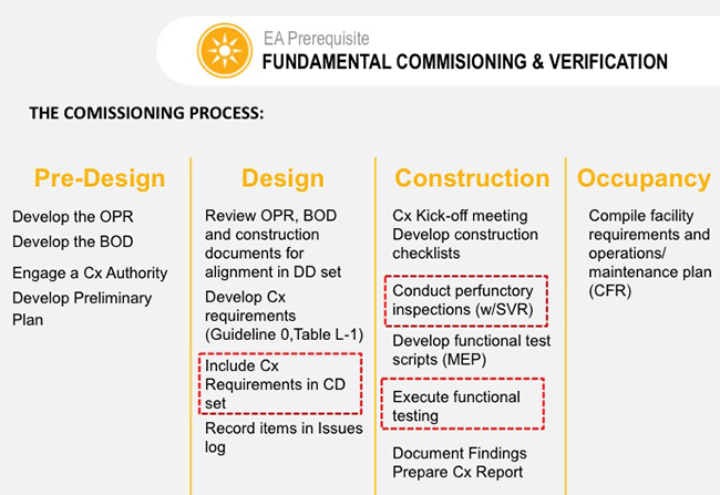
The commissioning process ideally begins at project inception (predesign phase) and continues in phase-specific functions through facility and system operation. It is not a design or construction function, but it assists in and verifies that the results of these functions can produce a facility and systems that meets the requirements for performance. Depending upon the Owner's needs, these might include; functionality, efficiency, sustainability, environmental and health impacts, interior occupancy conditions, resilience, and others that will maximize facility and system profitability for the Owner and the occupants.
Commissioning for new construction typically involves a CxP for all phases until the building is occupied:
Phase 1 — Predesign. It is important to start the commissioning process in the pre-design phase. This early involvement by the CxP is critical for the timely and useful development of the Owner's Project Requirements (OPR), the subsequent design team Basis of Design (BOD), the Commissioning Plan, and the beginning of the Operations & Maintenance (O&M) Systems Manual. If these tasks are left until later in the process and "reverse engineered" to match the design, their usefulness as catalysts for dialog, cost and risk management, and quality tracking tools is lost.
Phase 2 — Design. During the design phase the project design and details are further developed and organized for the construction documents. These documents must be based on the design team's application of the OPR. If questions and variations to these requirements evolve during this phase, it may be necessary to update the OPR with the acceptance of the Owner or representative. The commissioning requirements are further developed during design including the selection of the systems to be commissioned and the specifications detailing the functions of commissioning and the contractor's and manufacturers responsibilities as part of the commissioning team. The commissioning plan is further developed during the design phase to reflect the design and performance requirements of the commissioned systems and the initial development of field observation, functional testing, and performance requirements, along with documentation formats for testing and reporting. During and at the conclusion of project design, the CxP reviews the construction documents to determine compliance to the OPR and inclusion of the commissioning requirements. The CxP design review is intended to verify compliance with the OPR and is not considered a PEER review. Any open issues should be responded to in writing from the designer for design completion.
Phase 3 — Construction. In the construction phase, the commissioning process transitions from planning to application and is active during the entire construction phase. During pre-construction, the commissioning schedules are developed and integrated into the construction schedules. The CxP reviews the submittals for the commissioned systems and further develops the field observation, testing, and functional and performance requirements and checklists in the commissioning plans. The commissioning team is assembled along with the general contractor and relevant sub-contractors, manufacturers, and suppliers and these Cx Team members participate in a project commissioning scoping meeting for training and coordination. Subsequent meetings are conducted as needed, including systems integration meetings for both building controls and other building alarm and operating systems. An issues and resolution log is created by the CxP to communicate problems, concerns, and questions during the project to the Cx team and Owner. This log is updated during the project and the final log is included in the commissioning report. Depending upon the project organization, normally the contractors complete the installation field observations and checklists as required by the commissioning plan. These completed checklists are reviewed by the CxP and any needed adjustments are performed on the Functional Performance Tests (FPT) and schedules. In coordination with the construction schedules, the FPTs are conducted by the contractors along with the CxP as a witness. Based on FPT results, a preliminary commissioning report is drafted and reviewed by the Owner and, if necessary, the local jurisdictions. Any necessary plans for deficiency correction and off-season testing are included.

Reviewing the construction documents and coordinating with the construction team to ensure proper implementation of the project and commissioning plan. Photo Credit: 33684514, Ndoeljindoel/Dreamstime.com
Phase 4 — Hand-Off/Occupancy. At project substantial completion and after conducting operations and maintenance training by the design team (if applicable), contractors, and suppliers, the Owner assumes operational responsibilities for the facility or project. The commissioning process is not complete until the off-season testing is completed and the systems manual is completed and transferred to the Owner. At that time, a final commissioning report is developed including the final issue logs with any open items as accepted by the Owner.
NEW CONSTRUCTION/SYSTEM COMMISSIONING DOCUMENTATION
The new construction commissioning process includes multiple activities performed in a specific sequence. As defined in ASHRAE Standard 202–2018, Commissioning Process for Buildings and Systems, these functions are required to provide a complete commissioning project.
Initiation: The Owner or Owner's representative initiates the commissioning process at the beginning of the project. The roles and responsibilities of the project and commissioning teams are determined. Procedures and contracts are prepared and executed.
Owner's Project Requirements: Next, the project requirements are determined and documented which include the building program, use, scope, and the requirements for performance, sustainability, resiliency, training, testing, commissioning, and documentation. The deliverable for this activity is the Owner's Project Requirements (OPR) document which is the guiding instruction for the project. The OPR is updated throughout the design and construction of the project. See Determining Project Performance Requirements for further information on assembling the OPR.
Commissioning Plan: The initial Commissioning Plan is developed by the CxP that identifies the commissioning scope, roles and responsibilities, communication procedures, and design and construction requirements for providing and integrating commissioning into the project. The Commissioning Plan is updated throughout the project with checklists, schedules, and documentation details. The Owner reviews and accepts this plan.
Basis of Design: The design team determines and documents the design approach to meet the Owner's Project Requirements resulting in the Basis of Design (BOD) document. The CxP reviews the Basis of Design for conformance to the OPR. The Owner reviews and accepts this document before design completion.
Specifications: During the design phase, the contractor commissioning requirements are determined for each system and included in the commissioning specifications for the construction documents package.
Design Review: In the design phase, the CxP reviews the design and documents for conformance to the OPR. This design review also provides details that facilitate the further development of the commissioning plans.
Submittal Review: The commissioning team reviews the materials and equipment submittals for conformance to the OPR and construction documents. The submittals also provide information and details to develop project and commissioning process checklists.
System Verification: As the project is constructed, the commissioning team observes and verifies the installation and performs or witnesses the equipment start up and initial testing. Checklists and reports are prepared as required by the commissioning plan.
Functional Performance Testing (FPT): Functional and performance testing is conducted according to the commissioning plan to verify performance compliance with the OPR and design documents.
Issues and Resolution Log: Issues and resolution of issues are identified and documented by the commissioning team in the Issues Log along with related documentation. This log is a communication device for questions and problems from all the commissioning team participants that need solutions to facilitate successful project completion.
Systems Manual: During the design and construction of the project, the design and construction and verification documents are assembled into the systems manual. This assembly is normally performed by the general contractor or PM. This assembly of documents provides the details and history of the design and construction of the building and information needed to properly operate and maintain the building. The commissioning reports are included in the final Systems Manual.
Training: Training of facility staff should be pervasive throughout the commissioning process. At the hand-off/turnover phase, formal training ensures that operations and maintenance staff understand the equipment and systems. Training activities ensure that operators understand the theory ("why") as well as how to control and maintain the systems ("how") to operate and use the building in accordance with the OPR and design capabilities, the building operational staff and users are trained on the installed equipment and systems.
Seasonal or Deferred Testing: Commissioning activities that were not performed due to climatic conditions or equipment availability before initial certificate of occupancy are conducted during post occupancy. The final testing results are included in the final commissioning report and systems manual.
Commissioning Report: At the time of granting a facility Certificate of Occupancy a preliminary commissioning report is prepared that shows the commissioning progress and equipment performance to date. At the completion of the project, the final commissioning report is assembled and provided to the Owner and others as required by the OPR and local jurisdiction requirements.

Careful observation is an essential component of the documentation process during commissioning.
COMMISSIONING PROCESS MANAGEMENT
The facility or project Owner, or representative, defines and manages the process and reviews the documents. During project planning, the Owner also defines the extent and requirements of the commissioning process along with the basic commissioning team functions and responsibilities. Those functions are further defined in Roles and Responsibilities in the Commissioning Process.
The CxP normally reports to the Owner or Owner's Representative. This relationship and the contract need to be established at the beginning of the project. The function of commissioning is to assure the Owner that they are receiving true and full value in the function and performance of the commissioned systems. Thus, the reporting relationship to the Owner reduces or eliminates the possibility of a conflict of interest by the CxP.
Application
Building and/or System Commissioning Initiation
Engaging the CxP at the beginning of the project allows the CxP to become familiar with programming documents and proceed immediately to the OPR workshop and the development of the whole building criteria that match the project needs including facility certifications such as LEED®, Green Globes, Living Building Challenge, WELL, among others, and jurisdictional requirements. The OPR should be developed during the pre-design phase. When developed first, the OPR can become a very useful tool to the Owner in selecting the correct design and construction team for the project. During the selection process of the design team, candidates' responses to the OPR when submitting their BOD provides tremendous insight into their understanding of the OPR.
When the Systems Manual requirements are also started at this early stage, the inclusion of O&M requirements is facilitated. The inclusion of O&M planning in the early phases is key to the long-term persistence of energy efficiency, equipment longevity, and whole building performance strategies built into the design.
Sample commissioning process as outlined in ASHRAE Guideline 0 that informs NIBS Guideline 3, the basis for LEED Enclosure Commissioning. Photo Credit: USGBC
Determining Project Performance Requirements
Every new project goes through pre-design and design phases that establish an Owner's needs, goals, scope, and design solutions for a proposed project. Proposed designs and constructed work can only be evaluated against objective criteria and measures that are embodied in a well-documented OPR. Project development is a learning process where building performance decisions are refined to successive levels of detail over the course of a project's life cycle. This may also include possible future programs such as solar, recycling, and new technology.
The project performance requirements are defined and assembled in the OPR document. The OPR is also the foundation document of successful Cx. It is critical in ensuring the commissioning process meets the Owner's goals. The OPR defines the cost expectations, performance goals, energy and operational benchmarks, high-level schedule dates, operational approaches, and success criteria for the project. Owner staffing plans for the facility should be clearly identified so any impact on the design of the facility systems is known. The OPR must be developed with significant Owner input and ultimate acceptance. The CxP typically assists the Owner in identifying the facility's requirements regarding such issues as energy efficiency, indoor environment, staff training, and operations and maintenance. An effective OPR incorporates input early in the project from the Owner, operations and maintenance staff, and end users of the building, and is updated throughout the project. A properly developed and updated OPR truly becomes the definition of success for a project.
Defining Cx Requirements for a Project
The commissioning process can be applied to an entire facility or project or to limited and specific equipment and assemblies. The specific commissioning application is defined in the OPR. Subsequently creating the Commissioning Plan (Cx Plan) will answer the questions and set the criteria for the commissioning process on the project.
Key project requirements and related commissioning activities include:
- Establish goals for project quality, efficiency, certifications, and functionality of commissioned systems
- Establish a commissioning scope
- Establish commissioning budgets
- Assign team members and responsibilities
- Establish commissioning plans
- Establish commissioning schedules
- Establish testing and field observation plans
- Develop commissioning specifications
- Determine scope and content of commissioning documentation and reports
- Define special testing needs
- Develop Systems Manual format and requirements
- Determine operational staff training needs
- Establish ongoing building commissioning (OCx) plans and requirements
The project requirements and the systems and assemblies selected for commissioning determine basic commissioning functions and requirements. Additionally, the Owner can require variations and options in the requirements, such as sampling or specific testing, when needed on a specific function or project.
Project Documentation, Records, and Acceptance
The purpose of commissioning documentation is to serve as the historical record of the "what, why and how to" of key delivery team decisions throughout the planning and delivery process. Commissioning documents the establishment of standards of performance for building systems and verifies that designed and constructed work meets those standards. Key commissioning deliverables supporting Document Compliance and Acceptance are included above in the New Construction/System Commissioning Documentation section, and in Commissioning Documents: Process, Contents, and Acceptance.
Additional Resources
See the Additional Commissioning Resources page for more information.
Building Design Considerations in Cold Climates
Introduction
Within This Page
The content of this section of the BEDG in the WBDG is intended solely as a means to create awareness of the relevant topics and concepts. The following information is general in nature, consequently the application of the concepts discussed in real world conditions will vary based on project specific performance considerations and site specific microclimate conditions unique to each project, geographic location and building façade.
In the creative process of building design, a great deal of consideration is given to the physical landscape of a development. Orientation of the future building's footprint, entrances, exits, glazing, interior spaces, etc., are prudently arranged and manipulated to create the most aesthetically pleasing, efficient, and economical plan for the desired use of form and function.
This task of optimizing the readily observable attributes of a plan to its physical landscape can be a daunting task further complicated by the analysis of additional unseen non-physical factors. These factors often include the analysis or impact of: radiant solar angles, sun shadows, noise, vibration, wind force, air quality, pedestrian level winds, snow loading, etc. These last non-physical examples have been traditionally grouped into an area called Environmental or more accurately Microclimate Studies.
The term "microclimate" is defined by Merriam-Webster.com as: "the essentially uniform local climate of a usually small site or habitat". The purpose of conducting these non-physical studies is traditionally two-fold; first to understand the existing microclimate of the site from the various points of study; and secondly to predict the negative impacts, interaction, and influence of the proposed building design on the microclimate and modify the design to mitigate negative impact.
Consequently, the effort to create an aesthetically pleasing, efficient, and economical plan can have immense challenges and trade-offs. That said, the purpose of this particular resource page is to bring awareness to one specific non-physical microclimate factor for consideration in design: winter weather or winter precipitation and its potential for hazardous conditions to people and property if not adequately anticipated. Further it is important to note that the occurrence of hazardous winter ice and snow formations cannot be eliminated and can only at best be reduced in frequency or severity.
Description
The Problem Condition
The following text has been created to raise awareness of an old topic that is of growing concern based on some current trends in the economy and industry at large. Buildings in cold climates have struggled throughout the ages with ice and snow formations that slide, fall, or get windblown from their roofs, ledges, and window sills, causing harm to people and damage to property below. Sliding snow from residential roofs has damaged cars, blocked exits, or even torn off gutters and flashing details. On larger commercial or public buildings the issues are largely the same; however, the potential for damage or injury grows as building surfaces are larger, buildings are taller, and the volume of pedestrian and vehicular traffic increases.
In densely populated urban centers, such as New York City, Boston, Chicago, Toronto, Denver, and Washington D.C.; where prominent tall buildings are constructed on small sites with pedestrian and vehicular traffic mere feet from their base, the tolerance for any potential hazard or interruption of building operations due to falling ice and snow, or the erection of yellow "caution tape" is significantly less. Furthermore, experience has shown that public and urban buildings in general have very little tolerance for shedding ice or snow, regardless of the magnitude of the potential hazard, if it is thought that the occurrence will be perceived as a danger, or damage a building's reputation for safety. This leads to the question: what size of ice or snow piece is acceptable to fall from a building, and how often is it acceptable for ice or snow to fall?


Ice piece found on sidewalk that had fallen from a building ledge. Photo Credit: Northern Microclimate Inc.
A sight becoming far too common on city sidewalks in winter. Photo Credit: Northern Microclimate Inc.
At this time in the advancement of the study topic, the answer to those questions has not been agreed upon within regulatory organizations. Therefore, the best course of action is to seek knowledge and expert advice where possible.
The Art and Science of Ice and Snow Assessment
The assessment of ice and snow focusses on the totality of the winter microclimate in an effort to predict and mitigate a variety of impacts that include:
- falling snow prediction
- falling ice or freezing rain accumulations
- sliding or movement of ice & snow
- melt water control & icicle formation
- wind drifted snow formations
- windblown snow infiltration
- freeze thaw damage
- obstructed views from skylights & clearstory windows

A damaged barrier on a small building ledge. Photo Credit: Northern Microclimate Inc.
Different from a snow loading study, the assessment of ice and snow has no prescribed or regulated criterion, standard or procedure by building codes to assist designers or engineers. Furthermore, an ice and snow assessment focusses on events that would interrupt building operations, services, or create a perceived or real hazard to people or property, compared to snow loading studies that are focused mainly on structural integrity and the potential for failure at a prescribed criterion target. For example: in general, a 50–year return period design criteria for snow loading on a roof surface is prescribed by building codes and is considered acceptable by the established authorities, in regard to the potential for failure of a roof structure. However, there is no corresponding requirement for the acceptability (return period or otherwise) of a falling icicle, windblown ice or snow piece, or sliding ice and snow accumulation from a roof or façade surface.
The current state of the industry is largely due to the complexity of the issues and corresponding number of variables that need to be considered. Furthermore, the analysis and computational models that would be required to predict the potential for building designs to experience hazardous ice and snow formations is beyond the current capabilities of economic study. Thus, the industry must rely on experience-based assessments conducted by consultants having a broad knowledge and experience in: microclimate analysis, building science, cold climate testing, and field investigation.
Characteristics of an Ice and Snow Assessment
The assessment of the potential for ice and snow hazard is generally accomplished through a design review process that considers historical meteorological statistics, local topography and surrounding buildings or structures in combination with the proposed building design. This allows for the frequency, directionality, and severity of winter storm conditions on the site specific microclimate to be evaluated and expressed in terms of potentially problematic conditions. For example: which building façade will be most affected by strong winter winds during snowfall; which direction will freezing rain storms impact the proposed building most frequently; and, where on the exterior of the building are hazardous ice and snow accumulations most likely to form.
If potentially problematic ice or snow formations are anticipated, design modifications can be recommended to reduce the frequency and severity of hazards. The recommendations are typically derived from past experience, including cold room test results and research of previous successful designs and/or field studies. If there is limited knowledge of the performance of a particular design feature, material or the affecting microclimate condition with the corresponding design feature or material, the refinement and validation of a mitigation concept can be recommended. This process is typically accomplished by conducting a full-scale physical test in a controlled cold room environmental chamber. This type of testing can be costly, however it is necessary to allow for the creation of the specific microclimate conditions required (or in question) to validate and refine a mitigation strategy or concept before it is implemented.
To demonstrate the varied aspects of ice and snow assessment, the following topics are discussed:
Building Geometries within their Microclimate
Once historical meteorological statistics have been reviewed and assessed in combination with the proposed building geometries, potentially negative influences of the building's performance within the local microclimate can be realized and improved upon. Examples of negative geometry and microclimate interactions can include:
- orientation of building form (long axis vs. short axis) or shape (curved, round or block forms, etc.)
- complex roof shapes that include slippery sloped surfaces, barrel vaults, roof steps, tower and podium interactions
- complex wall assemblies and sloped surfaces (double façades, trombe walls, complex curtain walls, etc.)
- locations of pedestrian access and/or exterior amenity areas such as courtyards, parking spaces, etc.
If these potential issues are identified and evaluated early in design, the risks of ice and snow hazard can be managed and improved upon, reducing their impact on cost and schedule, and resulting in more appealing aesthetics, as integrated mitigation designs can be investigated.
Envelope Design Considerations
Similarly, the ice and snow assessment can contribute to the decision process regarding envelope design. It is becoming evident that strategies to reduce energy consumption in buildings have a direct impact on the performance of the exterior building skin. Solar shading devices, high-performance wall assemblies and glazing products are generating significant energy savings in terms of long-term building heating and cooling requirements. However, these same strategies are having a negative influence on the accumulation and life span of ice and snow formations on façade surfaces. For example:
- the addition of exterior solar shading devices has significantly increased the exterior surface area available for ice and snow formation
- to obtain increased resistance to heat loss, exterior wall assemblies have in some cases increased in thickness thereby creating larger ledges and window sills
- high-performance glazing products have reduced heat loss thereby promoting increased volumes of ice and snow formations on glazing


An example of increased exterior surface area created by the addition of sun shades. Photo Credit: Northern Microclimate Inc.
An example of snow formation on curtain wall glazing.Horizontal shading device wraps around the façade of the Center. Photo Credit: Northern Microclimate Inc.
Roof
The roof surface of a building can be a complex region, not only in terms of geometry or the presence of skylights, mechanical equipment, etc., but in terms of ice and snow design. Snow load considerations for ice and snow formations on roof surfaces govern the structural design of the roof and can significantly influence the entire structural design down to the footings of a building. However, as previously discussed, the prescribed snow load process is focused on long-term safety and durability of the structure to avoid catastrophic failure, and is therefore less focused on issues that can influence day to day building operations, public perception and the potential for falling, windblown or sliding snow hazards from a building.
Given these differences, there are two specific areas where the ice and snow assessment can contribute significantly to the structural design. These are sliding or moving snow on slippery sloped surfaces (metal or membrane roofs); and the integrity of the roof drainage path during the winter months.
The first topic has to do with ice and snow accumulations that in the correct meteorological conditions can slide or move, damaging roof projections, mechanical equipment, lighting protection, roof seams, parapet walls and in severe conditions the sliding ice and snow can slide completely from the roof surface damaging property or injuring people below. Circumstances that can lead to a sliding ice and snow scenario can be complex and are not well documented within the industry. This is where an assessment from an experienced ice and snow consultant can prove invaluable, if utilized during initial design rather than in a retrofit condition, which is often the case.

Sliding snow from a roof step on a smooth membrane roof. Photo Credit: Northern Microclimate Inc.
The second topic addresses a key assumption within snow load requirements, that all rain water and melt water from an ice or snow pack on a roof can readily leave the roof surface, therefore eliminating its contribution to the loading condition. However, in complex roof conditions or adverse meteorological conditions, a continuous warm (above freezing) path from source to drain for water flow may not exist. Gutters and roof drains have been known to freeze over with ice formations; alternatively, ice formations (an ice dam) at some location along the drainage path can block large roof areas from draining. Further complicating this issue is the application of heat trace to promote drainage. Often, the addition of heat trace is used to mitigate a potential blockage to the drainage path within gutters, downspouts and on roof surfaces. However, without specific knowledge of the ice and snow formations expected to be experienced, the application of heat trace can be ineffective or in some extreme cases cause problematic or hazardous ice formations. This again is where an assessment from an experienced ice and snow consultant can prove invaluable.
An ice and snow assessment can also help avoid potential issues: at clearstory windows and skylights (maintaining vision or sunlight as well as reducing leakage potential), at mechanical equipment and louvers (reducing snow ingestion or the drifting-in of equipment); and with the placement and size of screen walls and/or parapet walls.
Situating Entrances & Exits
The orientation, layout, or protection of building entrances and exits is also a task where the knowledge gained from an ice and snow assessment can be useful. Questions such as the following can be addressed in a timely and cost effective manner:
- Orientation to prominent winter winds
- Potential for snow infiltration
- Placement and detailing of canopies, wing-walls, wind screens, etc., as effective protection for building entrances and exits

Wind drifted snow cornice at entrance vestibule. Photo Credit: Northern Microclimate Inc.
Building Systems
The choice of building systems can also have an impact on the potential for hazardous ice and snow formations. Modern heating and ventilating systems, in conjunction with improved exterior wall performance, are reducing the reliance on perimeter heating, which in turn can increase the formation of ice and snow on exterior building elements. The overall impact can be a reduction in exterior skin temperature, which is small; however, the resultant increase in volume of ice or snow formation over an entire building skin can create problematic formations.
Planning for Occupancy
As the risk of hazardous ice and snow falling, sliding, or being windblown from a completed building cannot be eliminated under all possible winter conditions, it is therefore beneficial to provide guidelines to the building owner and future operations staff for the creation of operational protocols and winter maintenance plans with respect to ice and snow formations.
Emerging Issues
Energy Efficiency
In an effort to improve the overall energy performance of buildings, the profile of the exterior envelope or façade is changing. An increased use of solar shading devices or double façades has contributed to an increase in falling ice and snow incidents (these elements provide greater surface area for ice and snow to collect). Similarly, an overall increase in façade energy performance (i.e., increased insulation, reduced air leakage and better performing glazing) is contributing to larger ice and snow formations that can be windblown, slide, or fall from a building. Furthermore, the melt and re-freeze of accumulated precipitation on colder exterior surfaces contributes to dangerous icicles or ice sheets that can fall.
Design Trends
Building crowns, wing walls, large mullions, low or no parapets, green roofs, sloped walls and glazing (etc.); all contribute to falling ice and snow. Thus, a review of predicted winter performance of façade details during the design stages of a building is beneficial in identifying and reducing potential falling ice and snow risks.
Material Choices
Slippery roofs and sloped metal or glazed walls can allow ice and snow accumulations to slide and impact building components or areas below the roof or wall, posing a danger to people and property. Currently, there is little guidance available to address moving ice or snow on buildings. However, if the concern is identified during the design of a building and awareness brought to the potential for hazard, solutions can be sought.
Vegetative and cool roof construction techniques can each bring independent challenges to winter design.
The vegetative roof adds roughness and complex geometries potentially increasing the volume of snow collection on the roof surface, as well as increasing the potential for windblown snow transport on the roof surface, creating larger snow drifts in problematic locations. Furthermore, the build-up of soil and planting trays can create challenges with the melt water drainage path, possibly leading to ice formations at un-anticipated locations, creating localized loads. As well, freeze expansion damage to roof materials and flashing details can occur.
Cool roof construction, which is typically made up of increased insulation values combined with light colored roofing materials, has a significant impact on the rate of snow melt. The increased insulation reduces heat loss from the building's interior, while the light colored materials reduce solar absorbance. These two mechanisms can have varying impact on melt water production within an accumulated snow pack depending on the particular exterior weather conditions. However, in its simplest form, the melt out of snow will be slower, making the roof more susceptible to deeper snow, ice, and icicle formations, due to the potential for multiple snow storm events between melting periods. This in turn has implications to snow load assumptions, localized loading due to melt and re-freeze, and the formation of larger ice masses under deep snow formations that can promote sliding ice and snow and/or roof damage due to expansion forces.
New Technologies
Tall buildings can experience frequent wind driven icing at higher elevations. The ice collects in large volumes on parapets, cold walls, antennas, and other structural elements, and then falls. Incidents are rarely reported (publicly); however, they are frequent and increasing due to current design trends and the number of tall buildings. Experienced guidance is required to reduce potential of larger formations.
Relevant Codes and Standards
Building codes and standards have acknowledged the issues surrounding the potential for ice and snow movement on buildings, focusing on aspects of structural design. Some documents have gone further and acknowledge the potential for hazard and damage due to sliding ice and snow formations. However, the existence of procedures, instructions or guidelines that can be implemented to achieve a criteria or standard is not yet available.
Additional Resources
Publications
- Metal Roof Design for Cold Climates, Metal Construction Association.
Published Papers
- "Dam Ice Dam", ASHRAE Journal - Building Sciences 2010 by J. Lstiburek. June 2010.
- "Danger: Falling Snow" by D.A. Taylor. Published in Volume 35 Issue 1 of Canadian Architect, Reprinted in Construction Practice: Selected Applications in Construction Technology Section 2 (NRCC - 35475), 1990.
- "Minimizing the Adverse Effects of Snow and Ice on Roofs", Proceedings of the International Conference on Building Envelope Systems and Technologies (ICBEST-2001) by J. Buska and W. Tobiasson. Ottawa, Canada: 2001.
- "Sliding Snow and Ice on Buildings: a balance of risk cost and aesthetics", Proceedings of Snow Engineering V by C.J. Williams; M. Carter; F. Hochstenbach and T. Lovlin. London, England: Published 2004.
- "Sliding Snow from Sloped Roofs: Its Prediction, Potential Hazard and Mitigation", Proceedings of Snow Engineering VI by N. Isyumov. Whistler, British Columbia, Canada: 2008.
- "Sliding Snow on Sloping Roofs", Canadian Building Digest CBD-228 by D.A. Taylor. Institute for Research in Construction, November 1983.
- Snow and freezing water on roofs, Cold Climate HVAC by A. Nielsen and J. Claesson. Greenland Sisimiut: 2009.
- "Snow, ice and icicles on roofs - physics and risks", 7th Nordic Symposium in Building Physics by A. Nielsen. Reykjavík, Iceland: 2005.
Articles
- "Beware of Falling Ice and Snow: A winter perspective on building design", Construction Canada, Vol. 54, No. 1. by Mike Carter, C.E.T. and Roman Stangl, C.E.T., January 2012.
- "Winter Weather Considerations: Avoiding Ice and Snow Damage During the Winter Months" by William Meyers. Architectural West, March/April 2010.
Websites
- Snow Engineering—Snow and Ice Studies, Alan G. Davenport Wind Engineering Group, Boundary Layer Wind Tunnel Laboratory, University of Western Ontario
- U.S. Army Cold Regions Research and Engineering Laboratory Facilities and Products
Building Enclosure Design Principles and Strategies
Introduction
Within This Page
The innovative design of building enclosures relies less on successful past precedents than the application of building science. This is not because there is little to be learned from existing buildings, but is due to the changes in materials and methods that result from building technology innovation. Combined with growing expectations for high performance, building enclosure design is now required to satisfy a large number of performance parameters that were not given a great deal of consideration in the past. Building enclosures were always expected to be durable and provide a degree of environmental separation, but now they must address issues like energy efficiency, daylighting, indoor air quality, fire safety, thermal comfort, and carbon footprint. There is now a need to explicitly ensure these performance objectives are fully satisfied at the design stage.
Performance: the level of service provided by a building material, component or system, in relation to an intended, or expected, threshold or quality.
Performance-based design is not a new idea and in fields like structural engineering, limit states design has been deployed to reliably achieve appropriate levels of performance. There remain a number of challenges to overcome before a similar approach is available for building enclosure design. Until such time, the information that follows is intended to provide a practical framework for applying building science principles and strategies to the design of well performing building enclosures.
Before continuing with this Resource Page, it is highly recommended to review a summary of building science Vocabularyi in order to be consistent with the terminology used throughout the building science series of WBDG Resource Pages.
For those interested in knowledge enrichment, access Historical Development of the Building Enclosure to understand how ideas and technology have evolved.ii
Description
Principles of Enclosure Design
The requirements for wall performance were outlined some half a century ago (Hutcheon 1963)iii, and are applicable to all enclosure systems and components. The major considerations were identified as:
- Strength and rigidity
- Control of heat flow
- Control of air flow
- Control of water vapor flow
- Control of liquid water movement
- Stability and durability of materials
- Fire
- Aesthetic considerations
- Cost
Since Hutcheon's time, additional objectives have been adopted, such as consideration of the environmental impacts associated with building methods and materials, and the need to provide safe and secure buildings. The objectives or requirements for acceptable wall performance were implicit within traditional methods and materials of construction. With the advent of modern building science, these objectives became more explicit in response to technological innovation. Table 1 summarizes contemporary performance requirements and their corresponding assessment parameters.
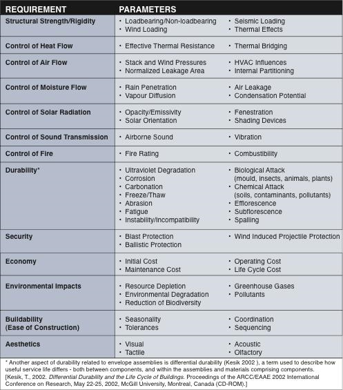
Table 1. Performance requirements for building enclosures and their corresponding assessment parameters.
Separator Versus Moderator
A critical principle in building science involves the difference between environmental separation versus moderation. For example, the control of fire and smoke movement is understood to be a strategy that attempts to completely separate smoke and fire from the indoor environment. The strategy employs a fire-rated assembly that fully controls the leakage of smoke by virtue of its airtight construction and in some cases, the control of air pressures between compartmentalized spaces.
Moderation involves a strategy where the severity of the difference between the indoor and outdoor environments (or two adjacent indoor environments) is moderated within a tolerable threshold. For example, the control of heat transfer does not seek to reduce the rate of heat transfer to zero, rather to a level that satisfies requirements for comfort, energy efficiency and the control of condensation/wetting. Table 2 summarizes key control strategies for the design of building enclosures, most of which involve a moderation strategy rather than a separator or 'perfect barrier' strategy.
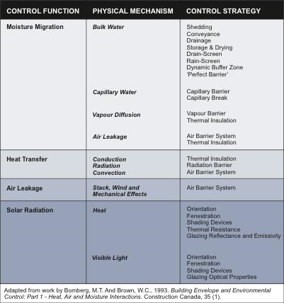
Table 2. Fundamental strategies for the control of heat, air, moisture and solar radiation in the design of building enclosures.
A review of the physical phenomena and corresponding control strategies indicates the control of moisture migration is by far the most important control function to be addressed by the designer. Moisture related problems in buildings are common and broadly vary in types and consequences. A brief listing of moisture related problems illustrates this point: frost heaving, adfreezing, water leakage, wood rot, mold growth, spalling, efflorescence, corrosion, and deterioration and staining of finishes. Consequences range from structural failure to cosmetic flaws, and in some cases the health of the occupants can be adversely affected as in the case of mold growth causing allergic and respiratory problems.
The list of the harmful effects of water in building materials and assemblies is indeed a long one. In many instances the water by itself is not harmful, and only when combined with other phenomena does it cause rapid deterioration. On the other hand, the other phenomena involved will not cause deterioration in the absence of water. It follows then that if water can be controlled a building can be made more durable and the maintenance and repair costs reduced. If this could be achieved only by the use of very expensive materials and construction it could be argued that it is better to let the building deteriorate and to replace the damaged portion from time to time. In fact, however, durable construction can be achieved with relatively inexpensive materials and designs, provided that the designer understands the behavior of water in its various forms and applies the necessary controls to prevent it from accumulating in harmful quantities.iv
Addressing the control of moisture in building enclosure design generally takes precedence over other control measures simply because so many of the requirements for the control of heat transfer, air leakage and solar radiation are satisfied when all forms of moisture management have been carefully considered.
A number of related pages are dedicated to explaining these various control strategies in depth:
For the purpose of applying building science effectively, it is important to appreciate the building enclosure is the primary environmental separator/moderator. It performs a passive role, unlike mechanical and electrical systems that actively supplement the amount of heat, air, moisture and daylight the enclosure is unable to provide. When all active systems fail, the building enclosure is the last line of defense between the indoors and the outdoors. High-performance building enclosures provide passive survivability during extreme weather phenomena and natural disasters, and safely shelter their inhabitants. The following section outlines a number of critical relationships and factors involved in the design of building enclosures.
Design, Materials, Workmanship
In order to appreciate the approaches involved in building enclosure system design strategies, it is important to understand several key relationships that impact performance.
Workmanship and materials are imperfect. If it is likely for a set of working drawings and specifications to contain errors and omissions, then it is almost a certainty that the translation of these instructions to contractors and their trades will be imperfect. Inaccuracy and inconsistency of workmanship and materials, in conjunction with variable weather conditions, result in buildings that only approximately fulfill their design intent.
Management approaches with respect to physical phenomena affecting the building enclosure system are shown through experience to be superior to barrier approaches. Not only do they provide redundancy of critical control functions, but they are more forgiving to construct, since tolerances are greater than those required by a barrier approach.
Enclosures must adequately control moisture migration, heat transfer, air leakage and solar radiation. Experience indicates that when the requirements for the control of moisture migration have been satisfied, the other control requirements are either simultaneously satisfied, or more easily satisfied than if moisture migration is not addressed at the outset.
In practical terms, these relationships guide designers to assume flawed construction that must be compensated with redundant control measures focused on moisture management. For experienced designers these assumptions are almost axiomatic.
Physical Phenomena
Environmental conditions, both internal and external, establish the physical phenomena that impact the performance of the building enclosure. In order to be durable and provide adequate moderation of the environment, the building enclosure must be designed to provide a threshold of control over, or resistance to, these phenomena.
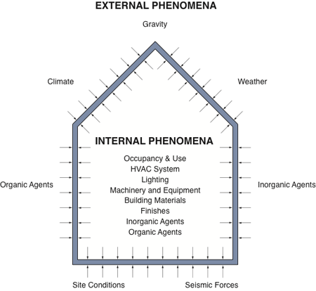
Figure 1. Imperfect building enclosures must manage all imposed internal and external environmental phenomena.
Intensity, Duration, and Frequency
All physical phenomena share intensity, duration and frequency as defining characteristics. Events such as earthquakes, tornadoes, hurricanes, and to some extent floods, are typically high intensity phenomena of short duration and low frequency. In most climate zones, vapor diffusion, heat transfer, and air leakage are normally low intensity phenomena of relatively long duration and seasonal frequency. Both types of phenomena have accounted for considerable damage to buildings, however, the strategies for dealing with each varies not only in terms of the actual control measures, but mainly according to the associated risks and consequences of failure.
Risk and Consequences
Risk of failure involves the probability of a specified level of performance proving inadequate to resist an imposed physical phenomenon or phenomena. The likelihood of failure must be reconciled with the consequences of failure in terms of safety, health, functionality, economy, and aesthetics. Minimum levels of adequacy for health and safety in buildings have been established through codes and standards, and guide the designer in these vital aspects of building performance. However, the risks and consequences of failure for a building requirement such as structural integrity are much better understood than for moisture protection. For this reason, many building enclosure design strategies are based less on probability and analytical models, and more on precedent, heuristics, and common sense. This does not suggest that analysis is completely abandoned, but instead acknowledges that the results are often only accurate to within one order of magnitude. Numerical data must be interpreted qualitatively, requiring significant experience and judgment on the part of the designer.
Durability and Redundancy
Durability is a key consideration in effective enclosure design and this requires that a level of redundancy be provided in terms of critical control functions for moisture, heat, air leakage, and solar radiation. [Resilience is a concept related to durability that applies to the design, construction, and operation of buildings and infrastructure that are resistant to natural and man-made disasters.v]
Redundancy—An enclosure with more than one 'line of defense' against imposed phenomena may be redundant with respect to one or more critical control functions. The degree of redundancy may range from: (i) resistance to each imposed phenomenon is distributed across all materials in the assembly (fully redundant); to (ii) resistance to each imposed phenomenon correspondingly addressed by individual materials within the assembly (non-redundant, hence each material represents a 'perfect barrier'). To be cost-effective and practical, redundancy is not simply doubling up on every control layer, or only selecting materials that address all of the control functions simultaneously. Control layers may be selected so as to perform more than one control function, or to significantly contribute to enhancing the performance of one or more control layers.
Multi-Functionality—A material may be uni-functional, such as a structural element, or it may address more than one required control function resisting imposed physical phenomena. Multi-functionality may be described as either: (i) single material addresses all enclosure control functions; or (ii) material primarily addresses one control function (first line of defense) and contributes to another control function(s), (second line of defense). For example, exterior insulating sheathing can act as a thermal control layer while contributing to air leakage and rain penetration control. If it is a vapor resistant material, such as extruded polystyrene, the exterior insulating sheathing can also resist vapor diffusion.
Contribution—A material may improve or enhance the performance of another material or assembly of materials without displaying multi-functionality or explicitly adding to redundancy. For example, an air barrier membrane may reduce air movement through an air-permeable insulation material, improving its thermal effectiveness but not contributing to the nominal thermal resistance of the assembly.
High-performance building enclosures provide high levels of resistance to imposed phenomena by intelligently arranging materials that are multifunctional with respect to critical control functions and contribute to the enhanced performance of one or more materials comprising the assembly.
Continuity
The continuity of critical control functions is among the most significant considerations when detailing building enclosures. Air and water leaks along with thermal bridges not only compromise performance but often lead to severe degradation of the building enclosure. In extreme cases, problems such as mold arise from a failure to maintain continuity of critical control functions. There are four Resource Pages that address building enclosure transitions to maintain continuity: Integrating the Building Enclosure; Wall to Roof Transitions; Wall to Window Transitions; and Wall to Foundation Transitions. For the purposes of enclosure design principles and strategies, it is extremely important to observe the need to achieve continuity of critical control functions, especially at transitions between enclosure assemblies.
Buildability and Economy
Lines on working drawings are straight, and the dimensions are precise, but in the field the building artifact is always an approximation, sometimes too crude an approximation to perform adequately. How does this come about?
Contractors and their trades are highly constrained by time and budget on virtually all construction projects. They are generally not inclined to spend more effort on construction than it is economically worth. If the successful (usually lowest) bidder on a construction project discovers that an assembly or detail is too expensive to execute properly, then ad hoc modifications (a.k.a. cutting corners) may be implemented by workers intent on meeting productivity quotas.
In some cases, the skill levels of the trades may be too low for the work they have been awarded. In other cases, the knowledge and experience of those performing quality assurance and supervision are simply not up to par. When none of the above factors come into play, other problems such as substandard materials or bad weather affect the quality of the finished product. Unforeseen site conditions, usually involving soils and groundwater, may compound the situation further, along with human factors such as labor disputes (strikes).
For these reasons, practical considerations in design should not be underestimated. Forgiving building systems that accept the reality of imperfect materials, workmanship, site conditions, and human factors are truly elegant and sustainable design solutions. Details whose proper execution demands the most efficient and least expensive methods are the real masterpieces of building enclosure design. This approach is certainly preferable to being 50% over budget on a project with a leaky roof, especially from the perspective of the building owner.
The economy of a building enclosure, in particular its initial capital cost, is largely determined by buildability, which also impacts its life-cycle economy if assembly of the enclosure exceeds the capability of the work force. Bad details lead to bad workmanship and ultimately poor performance.
Building Enclosure System Integration
The architectural design of building enclosures, foundations, walls, roofs, windows, and doors demands functional integration and aesthetic orchestration. Assuming that each of these assemblies and components has been individually resolved, it must be recognized that a second order of design/assessment is subsequently required. This ensures that the major assemblies and components are compatible, both mechanically at their connections and intersections, and in terms of their collective contribution towards the management of critical control functions. This iterative process from architectural concept, through physics, materials, and components, and back to the building as a system is a cornerstone of modern building science and its contribution to architectural design practice. Keeping these principles and key relationships in mind, the next section examines the critical physical phenomena that need to be considered in the design of effective building enclosures.
Climate, Exposure, Occupancy, and Building Energy Profile
Designing an effective building enclosure must properly consider the following factors:
- Climatic zone where the building is located
- Annual exposure to precipitation
- Intended use or occupancy of the building (interior climate class), and
- Building energy profile (skin-load versus internal-load dominated).
Based on these factors, it is possible to design building enclosures that adequately address all of the imposed physical phenomena while delivery high performance.
Climate Zones (Hygrothermal Region)
ASHRAE has defined 8 basic climate zones, some with variations, as listed in Table 3.
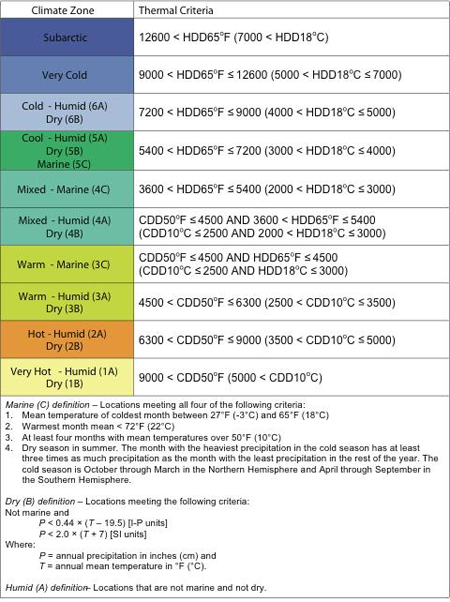
Table 3. ASHRAE climate zone definitions used for the design of hygrothermal control functions in building enclosures.
Climate zones influence the selection and arrangement of hygrothermal control layers in a building enclosure. The appropriate levels of thermal resistance may also be derived from the zone thermal criteria. Figure 2 depicts the hygrothermal climate zones of North America.
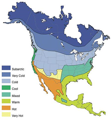
Figure 2. The selection and arrangement of heat and moisture (hygrothermal) control layers is based on climate zones. North America has all 8 climate zones and this broad range of climates explains why enclosures that are effective in one climate zone fail to perform properly in other climate zones.
Another way to understand climate zones is in terms of wetting and drying potential. All of the humid and marine climate zone variations in Table 3 have a high wetting potential and a low drying potential. This means that if the building enclosure experiences wetting due to moisture migration from either the exterior and/or interior, it will likely not dry out fully and be susceptible to mold and decay. Mixed, warm, hot, and very hot climate zones that are humid or marine will predominantly experience vapor migration across the building enclosure from the exterior toward the interior, while the cool, cold, very cold and subarctic zones will experience vapor flow from the interior to the exterior. The practical implications of these phenomena are presented in Understanding Air and Vapor Control Layers.
Precipitation Exposure
The annual quantity of precipitation is an indicator of the wetting potential of a particular geographic location, and also informs the selection of an appropriate cladding system that can adequately manage the amount of rainfall exposure.
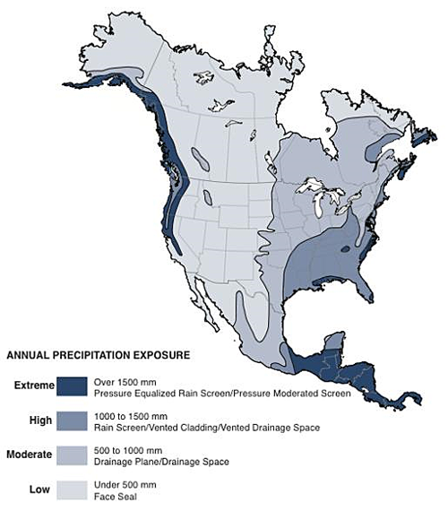
Figure 3. Annual precipitation exposure is a critical factor in the selection of a suitable cladding system that can provide adequate moisture protection.
Indoor Climate Class
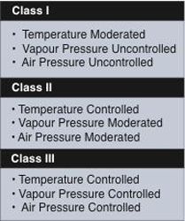
Table 4. Indoor climate classes based on a qualitative index advanced by Lstiburek 2002.vi
The building enclosure must also withstand environmental loads based on the interior building conditions. Table 4 outlines indoor climate classes based on temperature, vapor, and air pressure regimes. It should not be confused with ISO Standard 13788 characterization of indoor climate classes. Instead, it should be employed as a guide to the level of moderation or separation that must be achieved by the control layers. For example, a warehouse for storing non-perishable goods may be temperature moderated by a heating system set to prevent freezing but with no intentional means of controlling humidity or air leakage. As such, there will not be large gradients across the building enclosure and only minimal control layers will be required. On the other hand, in a facility where temperature, vapor, and air pressure must all be carefully controlled, such as a pharmaceutical laboratory, it will be essential to provide high quality control layers to provide adequate resistance across the full range of differential gradients that must be maintained within a relatively narrow tolerance.
It is important to note that the higher the climate class, the more environmental stress will be placed on the control layers. Not only do the materials comprising the control layers have to be properly specified, but their detailing to ensure continuity must also be carefully devised. In the past, building designers relied on the power of HVAC systems to manage indoor environmental conditions, but since the time of the first energy crisis in the early 1970s, there has been a steady move away from active systems of environmental control in favor of passive systems, primarily the building enclosure.
Building Energy Profile
From an energy efficiency and thermal comfort perspective, buildings are often classified according to the primary drivers for space conditioning loads. This translates into two major profiles of buildings: skin-load dominated; and internal load dominated. The design of the building enclosure must account for these characteristics to provide energy efficient operation and deliver thermal and visual comfort to the occupants.
Skin-Load Dominated Buildings
A skin-load dominated building has the largest proportion of space conditioning energy loads determined by the building enclosure. This type of building is characterized by a relatively low occupant density where internal heat generation is minimal (e.g., housing), and natural ventilation and daylighting may be easily accomplished. They are also located in a climate that is either cold or colder, or hot or hotter. Mild climates do not exert a significant temperature differential over a sufficient duration to render buildings skin-load dominated. This building type relies on high-performance windows set in a thermally efficient enclosure with minimal air leakage and thermal bridging. In general, skin-load dominated buildings benefit from passive solar heating strategies in cold climates and solar shading and natural ventilation strategies in hot climates. Typical skin-load dominated buildings include houses, apartment buildings, small commercial and institutional buildings.
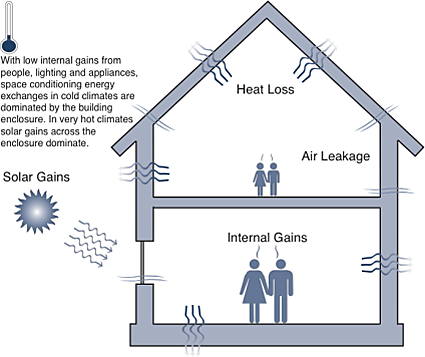
Figure 4. Skin-load dominated buildings benefit the most from high-performance building enclosures, and can take the best advantage of passive control strategies.
Internal-Load Dominated Buildings
Buildings that have high occupant densities and high internal gains from lighting and/or equipment are considered internal-load dominated buildings. Sometimes these are also referred to as a core-load dominated building. Regardless of climate type, the internal heat generation puts high demands on ventilation and cooling that are further driven by solar gains. For this building type, efficient means of rejecting excess heat generation translate into building enclosures that are typically less thermally efficient than effective at reducing solar gains by deploying shading devices and selecting appropriate optical properties of glazing. Different fenestration and shading strategies can also be deployed corresponding to the solar orientation of each face of the facade. Office towers and large retail facilities like shopping malls are notable examples of internal-load dominated buildings. Integration of the building enclosure with the HVAC systems is critical for achieving high performance in these types of buildings.
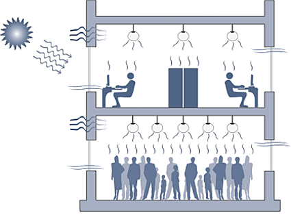
Figure 5. The energy performance of internal-load dominated buildings is strongly influenced by the window-to-wall ratio, effective U-value and solar heat gain coefficient of the glazing, and the airtightness of the building enclosure. Heat recovery for ventilation air and lighting system efficiency are the two most critical considerations for active building systems in these types of buildings.
There are also hybrid building types based on their changing occupancy. Schools are an example of buildings that are internal-load dominated when the classes are full during the day, and skin-load dominated on evenings and weekends when they are unoccupied.
It is important to appreciate that the hygrothermal design of a building enclosure to properly manage moisture, heat, and air flow is a function of the climate zone, precipitation exposure and indoor climate class. The building energy profile type is taken into consideration for the optimal levels of thermal insulation and selecting strategies for daylighting, passive solar heating, shading devices and passive cooling (natural ventilation).
Building Enclosure Design Strategies
Design strategies for building enclosures are a relatively recent opportunity for building designers. In the past, locally available materials and successful past precedents guided a highly traditional building industry where certain types of performance problems, (i.e., energy efficiency, thermal comfort, etc.), were considered acceptable. Today, a multitude of performance requirements must be satisfied amid a marketplace of innovative materials, components, and systems the designer is responsible to fully integrate, and the constructor must properly deliver. Picking a suitable generic building enclosure typology is an important first step.
Building Enclosure Typologies
The discussion that follows is focused on exterior walls recognizing that many of the considerations also apply to roofs and below-grade assemblies. It is interesting to note from Figure 6. that after thousands of years of building construction by humans, only a handful of building enclosure typologies have emerged. Most of these evolved by trial and error with some recent innovations arising from the application of building science principles, especially as it relates to rain penetration control.vii
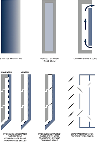
Figure 6. Schematic representations of basic building wall enclosure typologies.
Storage and Drying
Traditional masonry buildings relied on the storage and drying strategy for the management of moisture on a seasonal basis. The monolithic masonry façade was not only part of a load-bearing system, but also a hygric buffer with a capacity to store large quantities of water during wet periods, which are then released during dry periods. As long as the hygric buffer capacity was sufficient to store moisture accumulations, and the flow of moisture was not impeded at either the interior or exterior of the wall, this enclosure system would render good service. Some drawbacks of this strategy are the large quantities of materials and labor needed to erect the enclosure, the poor thermal efficiency due to a lack of insulation, and the absence of an air barrier system. Durability and moisture management are achieved at the expense of energy and thermal comfort. It is important to note that by abandoning this approach in favor of high performance, critical considerations have increased while margins of error have decreased.viii
Perfect Barrier
Modern building science experience has demonstrated that perfect barrier or "face seal" strategies for building enclosures do not have a high likelihood of acceptable performance, except for highly arid climate zones. The imperfect nature of materials and workmanship results in a high probability the perfect barrier will have discontinuities, either at the time of construction / assembly and/or after exposure to the elements. Maintaining a perfect barrier is a costly and perpetual proposition. Perfect barrier or face seal systems do not have any redundancy of critical control functions, have no provisions for draining unintentional water penetration, and should therefore be avoided in high-performance building design. Perfect barriers or face seal systems rely on tightly sealed joints using caulking and/or gaskets to resist water and air leakage. This approach has been applied to components such as windows and doors that are manufactured under controlled conditions in factories. The joint between the component (window) and the opening in the enclosure is also highly dependent on workmanship and material durability.
Dynamic Buffer Zone
The dynamic buffer zone is a strategy employed in the preservation of historic buildings where the exterior facade cannot be altered, but typically cooling is being provided through a modernized HVAC system. This is exclusively an enclosure retrofit strategy intended to create a buffer zone inboard of the existing facade, which continues to reside in its original hygrothermal environment.
Graduated Mediators
The most notable contemporary example of a graduated mediator is the double-skin facade (DSF), but there are many historical precedents where a system of overhangs, screens, and louvers manipulated insulation, shading, and natural ventilation to enhance environmental control. This strategy is usually associated with mild climates where the potential passive contribution of the enclosure is significant. In more extreme climates, a single enclosure assembly is generally preferred as this enables multiple lines of defense (in effect a compressed graduated mediator) to be incorporated cost-effectively into a more conventional building enclosure.
Pressure Moderated Drainscreens
This term refers to a family of enclosure typologies that deploy a cladding that has a vertical airspace behind it that is drained to the exterior. A drainage plane, usually in the form of a sheathing paper, prevents bulk water from penetrating past the air space. Pressure moderated drainscreens, also known as cavity walls in masonry construction, may be vented or unvented, with the latter approach being recommended for water absorptive cladding materials such as wood and brick. The fundamental principle behind this strategy is to make it much easier for the water to get out than to get in the assembly. Moisture management for this type of enclosure relies on the 3-Ds: deflection, drainage, and drying. This strategy can be deployed in a wide variety of enclosure types including, wood/metal/vinyl siding, brick/masonry, precast concrete, and EIFSix. Typically, this enclosure strategy is suitable for low and mid-rise buildings. For high-rise buildings, a pressure-equalized rain screen strategy is recommended.
Pressure-Equalized Rain Screens
Pressure equalized rain screens are an invention of modern building science. Drained cavities that proved effective in low-rise buildings evidenced air and water leakage on high-rise buildings due to extreme wind speeds. The concept behind pressure equalized rain screens is to create air pressure chambers behind the cladding by compartmentalizing the air space with baffles. Wind pressures would be neutralized in these pressure equalization compartments, thus eliminating a driving force for rain penetration. Considerable research has shown this approach to be effective even when it is not perfectly achieved in practice.x
Pressure equalized rain screen principles can be applied to a wide variety of cladding system including curtain walls. Best practices for the design and detailing of pressure-equalized rain screens have been developed to assist designers.ix
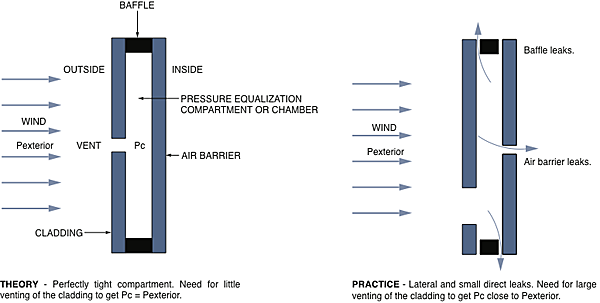
Figure 7. Pressure equalized rain screens are idealized drainscreens that manage air pressure differences through compartmentalization of the air space behind the cladding. In reality, the pressure equalization is not perfectly achieved, but rain penetration can still be adequately controlled with this strategy as long as a continuous, structural air barrier is provided.
Drainscreens, Rain Screens and Enclosure Fundamentals
There remains a great deal of confusion about drained enclosure assemblies, due in part by the nomenclature that has been used: cavity wall, rain screen, drainscreen, pressure-equalized, pressure-modulated, pressure-moderated, and rear ventilated are just some of the terms that may be found in publications. It is helpful to shed light on this fuzzy situation.
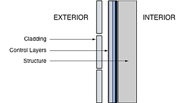
Figure 8. Enclosure assemblies that conform to building science principles of performance consist of three primary elements from inside out: the structure; control layers (heat, air, moisture, solar); and the cladding.
If it is generally acknowledged that the mass wall and the perfect barrier approach do not constitute feasible alternatives for high-performance buildings, then the only enclosures worth considering provide drainage and some degree of air pressure moderation. While the graduated mediator may be engineered to deliver a high level of control it is not off-the-shelf technology readily available in most building markets. The pressure moderated drainscreen, in a variety of forms and proprietary systems, is suitable for low to mid-rise buildings, and the pressure equalized rain screen is well suited to high-rise buildings. Regardless of the approach selected, building scientist Joseph Lstiburek has demonstrated it must conform to the schematic arrangement of enclosure elements depicted in Figure 8.xii
Important Note: The ordering of cladding, control layers, and structure do not change regardless of climate type. Cladding and control layers always reside outboard of the structure, which is held at a relatively constant temperature to minimize thermal stresses, and thereby maintain dimensional stability.
Lstiburek has demonstrated this arrangement is equally applicable to roofs and floor slabs, suggesting there are not nearly as many feasible enclosure typologies as might be portrayed by the wide variety of building materials, components, and assemblies available in the construction marketplace. The corollary to this observation is that only a subset of available building enclosure technologies is suitable to a particular combination of climate, exposure, indoor climate class, and building energy profile. Contrary to popular misconceptions, there are only a handful of successful building enclosure design strategies with proven past performance available to designers. xiii It is therefore advisable to ensure the proposed design solution conforms with a feasible generic building enclosure strategy that observes these fundamental building science principles.
Additional Resources
Publications
- Building Envelope by Canada Mortgage and Housing Corporation.
- Building Science for a Cold Climate by N.B. Hutcheon and G.P. Handegord. Institute for Research in Construction, 1983.
- Building Science for Building Enclosures by John Straube and Eric Burnett. Building Science Press, December 2005.
- Designing the Exterior Wall: An Architectural Guide to the Vertical Envelope by Linda Brock. John Wiley and Sons Inc., 2005.
- Evolution of Wall Design for Controlling Rain Penetration by G.A. Chown, W.C. Brown, and G.F. Poirier. Construction Technology Update No. 9, December 1997.
References
i. BSI-024: Vocabulary by Lstiburek, Joseph. Building Science Insight #024, September 9, 2009.
ii. BSD-007: Historical Development of the Building Enclosure by Straube, John. Building Science Digest #007, October 24, 2006.
iii. CBD-48: Requirements for Exterior Walls by Hutcheon, N.B. Canadian Building Digest #48, December 1963.
iv. Water and Building Materials by Latta, J.K. Canadian Building Digest #30, National Research Council Canada, June 1962.
v. Secure / Safe. WBDG Secure / Safe Committee.
vi. Moisture Control For Buildings by Lstiburek, Joseph, 2002. ASHRAE Journal, February 2002, pp. 36-41.
vii. Rain Penetration and Its Control by Garden, G.K. CBD-40. April 1963.
viii. BSI-039: Five Things by Lstiburek, Joseph. Building Science Insight #039, April 20, 2010.
ix. BSI-038: Mind the Gap, Eh! By Lstiburek, Joseph. Building Science Insight #38, February 22, 2010.
x. Facts and Fictions of Rain-Screen Walls by Rousseau, M.Z. Construction Practice: Selected Applications in Construction Technology, NRCC 35475, 1993.
xi. The Rain Screen Wall System by Canada Mortgage and Housing Corporation, Ottawa.
xii. BSI-001: The Perfect Wall by Lstiburek, Joseph. Building Insight #001, May 20, 2008.
xiii. BSD-018: The Building Enclosure by Straube, John. Building Science Digest #018, August 1, 2006.
Building Envelope Design Guide
The National Institute of Building Sciences (NIBS) under guidance from the past Federal Envelope Advisory Committee developed this comprehensive guide for exterior envelope design and construction for institutional / office buildings. Any edits, revisions, updates or interest in adding new information should be directed to the Building Enclosure Technology & Environment Council (BETEC) through the 'Comment' link on this page.
Introduction
Below Grade Systems
Wall Systems
- Cast-In-Place Concrete
- Exterior Insulation and Finish System (EIFS)
- Masonry
- Panelized Metal
- Precast Concrete
- Thin Stone
Fenestration Systems
Roofing Systems
Atria Systems
Related Materials
Related Resource Pages
- Air Barrier Systems in Buildings
- Blast Safety
- CBR Safety
- Building Design Considerations In Cold Climates
- Extensive Vegetative Roofs
- Flood Resistance
- HVAC Integration
- Indoor Air Quality and Mold Prevention
- Integrity Testing for Roofing and Waterproofing Membranes
- Seismic Safety
- Structural Insulated Panels (SIPs)
- Sustainability
- Wind Safety
The materials, components, and systems conveyed in these concept diagrams are intended to convey general design principles only. Any resemblance between these details and proprietary or otherwise commercially available materials, components and systems is purely coincidental and should in no way be considered an endorsement by NIBS and/or the individual authors who contributed to the content of this website.
Building Envelope Design Guide - Introduction
Introduction
Within This Page
Intended Audience and Subject Matter
The National Institute of Building Sciences (NIBS)–under contract from the Army Corps of Engineers, the Naval Facilities Engineering Command, the US Air Force, the General Services Administration, the Department of Energy, and the Federal Emergency Management Agency—has developed this comprehensive federal guide for exterior envelope design and construction for institutional/office buildings.
The scope covers buildings constructed of steel, reinforced concrete, reinforced masonry and reinforced concrete masonry units and includes low-rise, mid-rise and high rise buildings. Typical buildings include administration (office) buildings of all sizes, from a small one-story base administration building to a twenty-story inner city agency office facility. Other building types include firehouses and police facilities, courthouses, military residences, many types of laboratories, various types of education buildings, hospitals, extended care facilities, clinics and many types of recreational buildings. Special use buildings such as airplane hangers, testing facilities, and stadiums, single family residences and wood frame structures are not included.
Though specifically intended for Federal Government agency projects, the information in the guidelines will also be applicable to many privately developed projects—whether of a commercial or institutional nature—which are essentially similar in use and construction to equivalent governmental structures. Because the guidelines are intended for use in the design of governmental structures, the intent is to provide a long-lived structure based on lifecycle costing since governmental ownership is typical in perpetuity. Thus a high standard of construction and maintenance is advised to achieve the aims of the agencies involved.
Format
This is the first time a group of Federal agencies has developed a set of guidelines to be used for the design and construction of their buildings. Its publication and use is meant to assist in the development of uniform design and construction criteria for the Federal government. Instead of taking form as a printed document, which would be revised at long intervals, the Guide is made freely available as a "virtual" information source on the World Wide Web within the Whole Building Design Guide. It is anticipated that government agencies will devise methods of using the Guide to create their own "customized" documents to suit their building types, locations and administrative needs and to further their individual design and construction goals.
Private owners and their designers are free to use the Guide as a resource and can develop their own customized documents or simply refer their designers to useful sections of the Guide. The Guide is not a building code and does not attempt to specify mandatory criteria. Instead it provides design oriented information meant to assist designers in making informed choices of materials and systems to achieve performance goals in their buildings.
The Guide will be a "living" information source that will continually expand and change. It will be interactive, allowing users to enhance the content by adding resource papers, reporting on experiences, and helping to maintain a dialog with Guide management.
The details associated with this section of the BEDG on the WBDG were developed by committee and are intended solely as a means to illustrate general design and construction concepts only. Appropriate use and application of the concepts illustrated in these details will vary based on performance considerations and environmental conditions unique to each project and, therefore, do not represent the final opinion or recommendation of the author of each section or the committee members responsible for the development of the WBDG.
Scope
Richard Rush, in his book The Building Systems Integration Handbook, defines a building in terms of only four systems:
- Structure
- Envelope
- Mechanical
- Interior
In this categorization, "The envelope has to respond both to natural forces and human values. The natural forces include rain, snow, wind and sun. Human concerns include safety, security, and task success. The envelope provides protection by enclosure and by balancing internal and external environmental forces. To achieve protection it allows for careful control of penetrations. A symbol of the envelope might be a large bubble that would keep the weather out and the interior climate in."
Dr. Eric Burnett and Dr. John Straube, in a number of writings, have also described the envelope in terms of performance and function. According to them, the envelope "experiences a variety of loads, including, but not limited to, structural loads, both static and dynamic, and air, heat and moisture loads." The enclosure must then support structural loads and control environmental loads, which include both long-term and short-term loads. The enclosure is also often used to carry and distribute services within the building. In addition, the envelope (primarily the wall) has several aesthetic attributes that can be summarized as finishes. (This description of the envelope is expanded in the wall section of this Guide.) Thus the systems and assemblies of the envelope are one of the four main building systems both in terms of their physical existence and in their contribution to overall building performance.
For this guide the building envelope also includes the below grade basement walls, foundation and floor slab (although these are generally considered part of the building's structural system) so that the envelope includes everything that separates the interior of a building from the outdoor environment. The connection of all the nonstructural elements to the building structure is also included. Finally, it is recognized that the exterior envelope plays a major role in determining the aesthetic quality of the building exterior, in its form color, texture and cultural associations.
The following Building Envelope Systems are covered in separate chapters:
- Below Grade construction
- Exterior Walls, both structural (providing support for the building) and nonstructural (supported by the building structure)
- Fenestration, both windows and metal/glass curtain walls
- Roofs, both low- and steep-slope
- Atria.
This guide demonstrates that the design of the envelope is very complex and many factors have to be evaluated and balanced to ensure the desired levels of thermal, acoustic and visual comfort together with safety, accessibility and aesthetic excellence. As can be seen from the list of functions of the building envelope detailed in the Function and Performance section, the envelope plays a role in almost every building function, either directly or indirectly in its relationship to other building systems.
Figure 1 illustrates the envelope systems of a typical building.
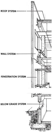
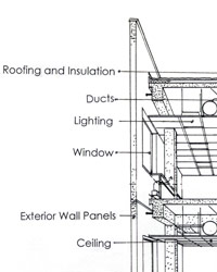
Figure 1. The building envelope systems: Left, the 4 systems; Right, a portion of the envelope showing some of the other systems that integrate with the envelope.
The guidelines for each of these systems are authored by an expert in the subject matter and are presented in the following uniform format:
- Introduction—An overall description of the system
- Description—The physical elements and properties of the system
- Fundamentals—A discussion of the design objectives to achieve ranges of performance
- Applications—The range of applications for building functions and external conditions
- Details—Generic construction details in CAD format with commentary
- Emerging Issues—A survey of significant current research and development
- Codes and Standards—Code philosophy and limitations and a summary of currently applicable codes and standards
- Resources—References, major publications, industry and professional associations, and Web sites
In addition, the following performance issues are examined for each of the envelope systems:
- Thermal performance
- Moisture protection
- Fire safety
- Acoustics
- Daylighting and perimeter visual environment
- System maintainability
- Material durability
Beyond these major performance issues the following more specialized building performance topics are covered by separate authors in concert with the principal system authors and, where appropriate, integrated into the main text for each system:
- Seismic safety
- Safety against blast and chemical, biological and radiological (CBR) attack
- Safety against extreme wind
- Safety against flood
- Indoor air quality and mold prevention
- Sustainability and HVAC integration
The Whole Building Design Guide
The Building Envelope Design Guide is one of a series of guides in the Whole Building Design Guide (WBDG) that are intended to assist designers in the integrated design of assemblies and systems. As such, the Building Envelope Design Guide follows the general format of other guides in the WBDG and are internally linked to Resource Pages and other levels and sections of the WBDG.
The Whole Building Design Guide (www.wbdg.org) is an evolving Web-based resource intended to provide architects, engineers and project managers with design guidance, criteria and technology for "whole buildings". Accordingly, the WBDG covers the whole range of today's issues in building design, such as sustainability, accessibility, productivity, and safety—both from human and natural hazards. The WBDG is constantly augmented with updated and new information and is structured as a "vertical portal", enabling users to access increasingly specific information as they navigate deeper into the site.
The concept of the Whole Building Design Guide has been formalized to achieve four main goals:
- To simplify access to government and non-government criteria and standards information using a web-based approach so that valuable time is not wasted searching for this documentation.
- To replace outdated, redundant paper-based criteria documents.
- To guide managers and A&E firms through a "whole building" approach to building design so that high performance, longer-lasting buildings are produced.
- To provide a brief, up-to-date and informative resource that covers general and specific topics in an encyclopedic form. However, unlike a traditional encyclopedia, the WBDG enables the user to build up a private store of relevant information by direct links to other resources available on the Internet with a few mouse clicks.
The WBDG has become a primary gateway to up-to-date-information on a whole range of Federal and private sector building-related guidance, criteria and technology from a "whole building" perspective. Users are able to access information through a series of "levels" by way of three major categories: Building Types, Design Objectives, and Products and Systems. At a lower level are Resource Pages, which are succinct summaries on particular topics written by experts. Pages within the WBDG are cross-linked to each other, and hyperlinked to external Web sites, publications and points of contact, allowing easy access to related information. Agency-specific information is accommodated in a Participating Agency section. Other features include relevant Federal mandates, news headlines and a robust search engine.
The WBDG Web site is provided as an assistance to building professionals by the National Institute of Building Sciences (NIBS) through the funds and support of the NAVFAC Criteria Office, the U.S. General Services Administration (GSA), and the Department of Energy through the National Renewable Energy Laboratory (NREL) and the Sustainable Buildings Industry Council (SBIC). A Board of Direction and Advisory Committee, consisting of representatives from Federal agencies, private sector companies and non-profit organizations guide the development of the WBDG.
The Evolution of the Building Envelope
The Building Envelope Design Guide will constantly evolve, with its users participating in this evolution rather than simply using a set of fixed, definitive guidelines. They will thus be advancing the evolution of the building envelope itself. The first building envelope that protected humans from the elements was probably a cave that provided a degree of privacy and security. The earliest building envelopes were dome-shaped structures that combined wall and roof (Figure 2A). At an early stage, however, the two dominant forms of envelope evolved, depending on climate and available materials: the timber frame and the masonry wall (Figure 2B and 2C). Early shelters in the warm climates of Africa and Asia used timber or bamboo frames clad with leaves or woven textiles. In other regions and climates heavier indigenous materials such as stone, rock and clay baked by the sun were used to provide more permanent shelter and protection from the heat and cold (Figure 2D).
To this day rural regions in lesser developed countries still construct these forms of shelter. In the developed world we still use envelopes of timber frame and masonry walls, although both have evolved into a wide range of materials—some natural, others synthetic. Roofs evolved independently as waterproof elements with their own set of materials.


Figure 2. Steps in the evolution of the building envelope: (clockwise from top-left) 2A A dome shaped hut in Ethiopia combines wall and roof in one material; 2B Timber frame and thatched roof, Solomon Islands; 2C Masonry wall, Machu Picchu, Peru; 2D Packed mud dwellings, Yemen Arab Republic.
Thus, eventually the roof, wall and floor became distinct elements of the building envelope that have continued to this day with very little change in concept, use and even material. A medieval dwelling might have walls of wood, brick or stone, a wood roof structure, a slate tile or thatch roof and a floor of stone or hardened dirt. Such a dwelling can still be found today in many regions of the United States and the world.
To take one element of the envelope, the wall, its basic performance requirements have remained the same from medieval times to this day: protection of the interior from the elements and security for its occupants. However, our expectations have vastly increased, both in terms of absolute performance and the ability to control the impact of exterior water, sunlight and the ambient outside temperature on our interior environment. Depending on a society's structure and economy, such needs as degree of permanence of our exterior system, its scale and adornment and our desire to have a wide variety of exterior envelope choices may also vary considerably.
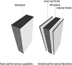
Figure 3. The ancient and medieval wall on the left attempts to provide all the envelope functions with one material. Later, right, decorative finishes were added to the exterior and interior of the wall.
Compared to most of today's walls the medieval or renaissance masonry wall was simple. Initially the wall was a single homogeneous material—stone or brick-exposed on the exterior and interior. Such walls are still constructed today, although the wall is more likely to be reinforced concrete or concrete block. Before long, the historic wall would become adorned: a rough structural stone would be faced on the exterior with a precisely cut and fitted facing of fine stone or marble, and the interior would be faced with smooth plaster (Figure 3).
As soon as the structural wall became faced with different finish materials the beginnings of variable performance capability emerged. The separation of the structure and facing presaged the layered exterior wall of today. The structure of rough cut stone could rise independently from its facing, which could be prefabricated in the craftsman's shop. The high-quality facing and its detailing also provided protection from the weather for the structural masonry within (Figure 4).


Figure 4. Structural masonry and decorative facing, fifteenth century Florence, Italy: 4A a rough stone structure (the facing was never completed); 4B A marble facing.
Historic buildings and even historic revival buildings accomplished many of the building envelope functions by default: thick, heavy masonry was fireproof and good for insulation in both summer and winter. It was excellent acoustically and, with sheltering roofs and good water protective details, was reasonably watertight and draft free by the standards of the time. However, by modern standards, the wall had fixed and limited performance capabilities.
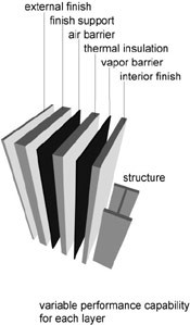
Figure 5. The layers of performance. The performance of each layer is variable. Some materials may perform more than one function, and their position in the layer may change according to the climate.
The big change in the concept of the wall—and the real beginning of today's concept of the building envelope—occurred with the invention of the steel, (and later, the reinforced concrete) frame in the nineteenth century. The exterior wall could become a screen against the elements and no longer be needed to support the floors and roof. However, for several decades steel frames were buried in masonry walls, and buildings continued to be designed in gothic or renaissance styles. The modern architectural revolution beginning in the early 20th century changed this and by mid-century the steel or concrete framed office building with its lightweight metal and glass curtain wall had become the new world-wide vernacular for larger commercial and institutional buildings.
When the wall became a nonstructural screen-in and no longer supported the upper floors and roof, it lost the beneficial attributes of mass but gained in providing performance options. Whole new industries arose that would develop insulation and fireproofing materials, air and moisture barriers and interior and exterior facings. More recently the exterior wall has become a major subject of building science studies, largely because of the wall's key role in managing heat gain, heat loss and moisture penetration. As a result, the modern wall now consists of a series of performance "layers" (Figure 5).
A cross section of a typical layered exterior wall of today illustrates the complexity that this approach leads to in practice (Figure 6).
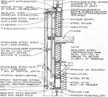
Figure 6. This section through a typical nonstructural exterior wall within a steel frame building structure shows the complexity of the layered approach in its application. Photo Credit: Architectural Graphic Standards
A different material may achieve each performance requirement, with each performing a separate function, or some materials may perform multiple functions. For example, the air barrier may simply be a coating on a support layer.
Function and Performance
The complexities of today's wall can also be exemplified by listing its functional requirements, or needs that must be met. There are at least 13 distinct needs, as listed below. Most of these functions also apply to fenestration and the roof and a few also apply to below grade construction (see Table 1 in Section 7). Each function (with a few exceptions) has its own performance standards and methods of measurement, methods of testing for compliance, and acceptability criteria.
- Structural: If the wall is not part of the main building structure, support own weight and transfer lateral loads to building frame.
- Water: Resist water penetration.
- Air: Resist excessive air infiltration.
- Condensation: Resist condensation on interior surfaces under service conditions.
- Movement: Accommodate differential movement (caused by moisture, seasonal or diurnal temperature variations, and structural movement).
- Energy conservation: Resist thermal transfer through radiation, convection and conduction.
- Sound: Attenuate sound transmission.
- Fire safety: Provide rated resistance to heat and smoke.
- Security: Protect occupants from outside threats.
- Maintainability: Allow access to components for maintenance, restoration and replacement.
- Constructability: Provide adequate clearances, alignments and sequencing to allow integration of many components during construction using available components and attainable workmanship.
- Durability: Provide functional and aesthetic characteristics for a long time.
- Aesthetics: Do all of the above and look attractive.
- Economy: Do all of the above inexpensively.
Performance refers to the desired level (or standard) to which the system must be designed for each of the above functional requirements. For example, what dimensions of movement must be accommodated, and what is the expected useful life, or durability, of the system.
Cost Management
The building envelope represents a substantial percentage of a building's cost. (Some typical costs presented as a percentage of the whole building cost are shown in Table 1, below.) For a multi-story building, the envelope costs (dominated by the cost of walls and fenestration) may even exceed 20% of the total building construction cost.
The envelope is also a critical system in the determination of the overall performance of the building, with an emphasis on the thermal environment, lighting and acoustical characteristics. It is the prime determinant of the exterior aesthetic quality of the building. Clearly, the balance between the cost of the building envelope and its levels of performance will be of great importance in achieving the most cost-effective design of a building.
| Table 1. Typical building envelope costs as a percentage of whole building cost | ||||
|---|---|---|---|---|
| Building Type | Floor Slab | Exterior Wall | Roofing | Total |
| Hospital, 4-8 floors | 0.6 | 9.5 | 0.6 | 10.7 |
| Manufacturing Plant, 1 floor | 6.4 | 9.5 | 6.7 | 21.6 |
| Office, 12-20 floors | 0.3 | 19.9 | 0.4 | 20.6 |
| JR. High School, 2-3 floors | 2.3 | 14.5 | 2.5 | 19.3 |
(Source: Means Square Foot Costs)
The Building Envelope Design Guide does not attempt to provide cost information for estimating purposes. There are a number of reasons for this:
- Construction costs fluctuate and rapidly become out of date. Published indices attempt to ameliorate this problem but they tend to be very broad in scope and are of limited use in application to a specific project. Also the state of the local market at the time of bidding and construction often has a major effect on cost.
- Construction costs vary greatly according to the project location. In broad terms, in the U.S. there is approximately a 200% spread between the least and most costly states in terms of construction cost.
- Very rapid change in cost—generally upward—in such key materials such as steel and lumber are common and cannot be predicted in advance.
- Government agencies and other institutions and businesses that manage large construction programs generate detailed cost information that refers particularly to the type and quality of the buildings they construct. This forms a valuable database that is specific to the owner's location and needs. Architectural and engineering firms and contractors also develop cost data that applies to their projects.
- Specialty construction cost estimating and management firms develop very large and detailed databases on cost because they are focused entirely on cost management issues. On any significant project they should be employed from the outset as part of the design team with responsibilities for cost management.
For these reasons, the developers of the Building Envelope Design Guide believe that cost management should be based on local information procured before the design process for budgeting purpose and during the design process for cost management purposes. The use of life-cycle costing, economic analysis and value engineering can be used to the extent that they suit the owner's economic goals. Clearly an agency or institution that expects to own a building for its entire useful life is well advised to budget on a life-cycle, and many government agencies now require that this be done.
Private owners may have other aims, but the ultimate building operators will all benefit from a building in which life-cycle costs have been considered. A future in which it is clear that energy costs must be expected continually to rise—with the possibility of energy itself becoming scarce within today's building lifetime—makes it the more necessary to design for minimum energy usage consistent with meeting functional and environmental needs. Building envelopes designed with opportunities for the use of day lighting and natural ventilation obviously can play a major role in such considerations.
Function, Performance, Design and Construction Relationships
The systems and elements that comprise the building envelope are each discrete assemblies that, in many instances, are designed by specialist consultants and installed by specialist sub-contractors. The mechanical system, for example, will be designed by a specialist engineering consultant and installed by several different mechanical sub-contractors. Some assemblies have a variety of methods of design and procurement. A metal and glass curtain wall may alternatively be a proprietary catalog assembly, a custom assembly designed by the architect with input from manufacturers or a consultant, or designed by a consultant to meet the architect's requirements. Each system, however, also has functional, performance, design and construction relationship to others.
Functional performance for the thermal environment, moisture protection, sustainability and durability are shared by all 4 of our major subsystems: walls, fenestration, roofing and below grade. Thus each has to be designed to contribute its appropriate share of the overall functional effectiveness in meeting the performance requirements for the whole building. Acoustic performance for the exterior is the responsibility of the wall system and, to a lesser extent, the fenestration, while daylight transmission and control is the responsibility of the fenestration and the roof (if there are skylights, although these will be designed by the fenestration designers). Natural ventilation, if provided, will be a fenestration design problem but will also have major repercussions on the HVAC design. If the HVAC system employs perimeter heating or cooling this must be integrated with the envelope performance requirements. Interior air quality is primarily an HVAC issue, mainly concerned with outside air supply and filtering. The exterior wall will also have some performance requirements relating to materials and permeability.
These relationships and some others are "flagged" in the matrix shown in Tables 2 and 3. Table 2 shows the list of basic performance requirements that are covered in this guide. Table 3 shows the list of secondary performance requirements that are covered. In addition, aesthetics is shown as an "influence". Unlike the other performance requirements, aesthetics is not subject to scientific testing and measurement. Nonetheless—particularly for the wall and fenestration systems of the building envelope—it is a powerful influence in the system and material selection process. The attributes of color, texture and pattern are familiar. The attribute of "association" refers to issues such as the use of stone to represent solidity and permanence (besides its possible measurable attributes of durability), or the desire of some colleges to require red-tile roofs on new campus buildings.
The group of practice considerations refers to issues that appear in all systems and are critical to the successful implementation of the whole project, from concept to commissioning. Innovation refers to emerging methods, materials and processes that may improve the performance, cost or appearance of a system as a whole or any element of it.
Key:
X Major determinant or influence
(X) Minor determinant or influence
| Table 2. Function and Performance Relationships of the Building Envelope: Basic Performance Requirements | ||||||
|---|---|---|---|---|---|---|
| SYSTEMS | WALLS | GLAZING | ROOF | BELOW GRADE | COMMENTS | |
| BASIC PERFORMANCE REQUIREMENTS | Thermal | X | X | X | Wall and glazing insulation and relative quantities largely determine thermal performance in medium and high rise buildings (small footprint), roof more influential in low rise (large footprint). | |
| Moisture Protection | X | X | X | X | All systems important, particularly glazing interface with walls, roof interface with skylights. | |
| Acoustics | X | (X) | Protection against outside acoustic environment. Walls major determinant, with glazing a secondary influence. | |||
| Light Transmission | X | (X) | Glazing major determinant, both quantity and location: roof may be important if skylights are provided. | |||
| IAQ | (X) | (X) | HVAC system is major determinant, together with natural ventilation (operable windows) if provided. Wall openings (grilles) must provide outside air supply to HVAC system. | |||
| Mold Protection | (X) | (X) | HVAC system is major determinant, together with natural ventilation (operable windows) if provided. | |||
| HVAC Integration | X | X | (X) | Wall and glazing insulation are critical in determining HVAC loads, together with roof if large footprint building. | ||
| Natural Ventilation | X | Operable glazing is traditional way of providing natural ventilation, but coordination with HVAC system is essential to ensure energy efficient system. | ||||
| Durability | X | X | X | X | All systems contribute to overall durability of building. | |
| Sustainability | X | X | X | (X) | Materials and performance of walls, glazing and roof have major influence: below grade construction may contribute but few alternative are available for design and construction. | |
Key:
X Major determinant or influence
(X) Minor determinant or influence
| Table 3. Function and Performance Relationships of the Building Envelope: Safety, Aesthetics, Practice and Innovation | ||||||
|---|---|---|---|---|---|---|
| SYSTEMS | WALLS | GLAZING | ROOF | BELOW GRADE | COMMENTS | |
| SAFETY REQUIREMENTS | Fire Protection | X | X | X | Wall, glazing and roof materials are critical and strongly regulated by code. HVAC and fire protection systems are key systems for smoke and fire reduction and elimination. | |
| Floods | X | (X) | X | Below grade and first floor wall construction are critical but building location is the key determinant. Protection of low level glazing is important. | ||
| High Winds | X | X | X | Building envelope is particularly vulnerable to high winds because wind action attacks the building exterior surfaces. | ||
| Seismic | X | X | (X) | X | Building structure is main defense against earthquakes. Heavy nonstructural precast wall panels and glazed curtain walls may need special attachment detailing to structural frames subject to large racking deformations in high seismic zones. Heavy roof materials (tile) are vulnerable and need positive attachment. | |
| Blast, CBR | X | X | X | X | Building structure is main defense against blast: non-structural wall panels and glazing need special design and attachments to structure, roof may contribute debris due to suction effect. HVAC main protection against CBR. | |
| AESTHETIC INFLUENCES | Aesthetic | Aesthetic issues primarily relate to building exterior (public view) and interior of exterior wall ( occupant view). | ||||
| Color | X | X | X | Related to materials: natural (stone etc) metals (metallic or painted finishes) and availability of a range of alternatives. | ||
| Texture | X | X | X | Smooth (metals), smooth to rough (natural materials, such as marbles, granites etc) and cast textures on concrete. | ||
| Pattern | X | X | X | Primarily related to joints between panels and glazing, and the size and shape of panels. | ||
| Associations | X | X | X | Local context and cultural associations, e.g. natural stone versus stucco. | ||
| PRACTICE CONSIDERATIONS | Cost | Pervades the choice of all materials and systems. | ||||
| Material | X | X | X | X | Cost and availability of materials. | |
| Installation | X | X | X | X | Cost (and time) of installation. | |
| Life Cycle | X | X | X | X | Evaluation of cost and performance in relationship to owner's (and society's) needs and resources. | |
| Codes & Standards | X | X | X | X | Pervades the use of almost all materials and systems. | |
| INNOVATION | Innovation | Includes the need for innovation and trends in innovation, through research and market forces initiated by codes and regulations e.g. developments in glazing technology to respond to energy conservation codes. | ||||
| Performance | X | X | X | X | Performance enhancement is a continuing goal, often related to marketing. | |
| Cost | X | X | X | X | Strongly driven by competition induced by bidding process. | |
| Aesthetic | X | X | X | A strong driver for exterior materials and finishes, glazing and steep slope roofing. | ||
The functional and performance relationships shown are also accompanied by physical connectivity. Many of the building envelope assemblies are connected to and supported by the building structure. Since the envelope receives certain loads—such as wind and seismic, and, in some instance—blast, its members must be capable of distributing these loads to the building structure besides resisting them within their own subsystems. Obviously, if the HVAC system employs perimeter heating and cooling, the distribution system will be part of the overall building HVAC distribution. The physical relationship of the roof assemblies to the structure is critical to their performance.
These relationships mean that the building envelope cannot be designed in isolation. It is a function of design management to ensure that the performance attributes and the physical connections between the envelope and the rest of the building are integrated in concept and execution from the commencement of the design process.
Safety, Security and Building Codes
Safety has long been the traditional focus of building codes, starting with the earliest codes related to fire safety. Protection against earthquakes has been the subject of codes in seismic regions for the last three quarters of the twentieth century. These codes have become very highly developed and have a strong engineering and scientific base assisted by governmental, institutional or industrial programs of research and development. Some codes also mandate requirements for floods and high winds, but these are much less developed than those for earthquakes.
In general, the intent of codes has been to mandate minimum standards that provide acceptable safety at an affordable cost. While codes also provide some property protection, this has not been a major target and has not been a stated intent of the codes. Many features of building codes are understood to represent a minimum standard and in practice are almost always exceeded for reasons of comfort and amenity. For example for many decades all U.S. building codes have agreed that the minimum floor area of a bedroom is 70 square feet with a minimum dimension of 7 feet in any horizontal direction; however, few bedrooms in even the most economical tract house are of this size.
Codes that do not appear to offer an accepted everyday benefit—and that are seen as adding cost to the project—are all too often treated as a maximum. This has created problems when buildings correctly designed and constructed to a seismic code have suffered significant damage—which the code permits, provided that life safety is not compromised. In part owing to the success of codes in protecting public safety, attention has begun to shift toward property protection because of the large economic losses incurred by earthquakes, high winds and floods. This loss is only partly due to the cost of repair and reconstruction; deeper economic losses are incurred by business and service interruption and losses such as market share and tourism.
As a result, designers are being encouraged to create designs for performance against natural hazards that are appropriate for a building's occupancy, function and importance. This means designing for an acceptable level and type of damage. This also generally means designing for performance above that anticipated by normal code-conforming design.
Another development in design against natural hazards has been the encouragement of multi-hazard design. The intent here—as in many other developments in the design process—is to implement a higher level of design integration. This involves ensuring that buildings subject to more than one natural hazard—for example both floods and earthquakes—take advantage of design methods that assist in countering all the hazards that apply and identify and find solutions for those instances where measures may conflict. Thus while elevating a building above grade is an excellent solution for design in a flood plain, great care must be taken to avoid "soft first stories" that have proven disastrous in earthquakes.
While building safety has traditionally focused on natural hazards, building security is focused on societal and political hazards—those created by criminal or disaffected members of our own society or foreign elements that see the U.S. as an enemy. Some degree of concern has always been present in design, of which keys and locks are the most familiar. Remote surveillance systems have been around for some time in retail stores and other sensitive environments. The tragedy of September 11, 2001 and the condition of war that has existed since that time have thrown a much more intense light on the need for building security.
The major difference between attack hazards and natural hazards—beyond a deliberate attempt to damage the building and cause casualties—is that of probability. Although natural hazards vary greatly in probability there is considerable statistical information on the issues of where, how big and how often a given hazard will occur, and considerable scientific study is devoted to this topic. Human-caused hazards have very little history, and the relatively few instances provide a very poor statistical database. As a result, it is at present very hard to know the extent to which it is prudent to take steps to mitigate attack by blast and/or chemical, biological and radiological (CBR) weapons. Meanwhile, much research and development is underway, ranging from testing vehicle barriers to the development of building code provisions that reduces the risk of progressive collapse from damage as a result of bombing.
This is an area that may be expected to evolve rapidly. Some of this evolution will be technical. Some will be societal and political as it begins to become apparent how large and how long-term the threats remain. The questions of where, how big and how often need much more convincing answers than are available at present before the full impact on building design can be gauged. Meanwhile, this subject is superimposed on the traditional range of issues with which the designer must grapple. Again, the need is for design integration with of security concerns considered from the outset.
Innovation
Although many historic materials are still in use—roofs are still constructed of copper and slate, and walls employ natural stone—the building envelope has been a prime target of innovation since the first quarter of the twentieth century. Innovation has been most significant in the wall and fenestration systems of the envelope and has been driven by four main influences:
- Cost reduction for a competitive market
- Enhanced performance
- Material innovation and industrial research & development
- Aesthetics
These influences are all related to one another. Much industrial research and development has been aimed at obtaining a competitive edge through performance improvement or cost reduction. For example, pre-cast concrete fabrication enjoyed about two decades of great success because the material and shapes appealed to architects. Innovation in pre-casting techniques, form design and fabrication and surface finishes resulted from collaboration with architects and the effort to be competitive as a supplier. Ultimately, however the pre-eminence of the pre-cast panel fa¸ade was seriously threatened by the rise of glass fiber reinforced concrete, a synthetic material innovation that was lighter and more economical than concrete and more easily formed into sculptured shapes.
The construction industry is intensely competitive. Much of this stems from the traditional approach to contractor and supplier selection—the competitive bid. This places a premium on lowest cost, resulting in innovation by contractors and sub-contractors trying to get an edge on their competitors. Another aspect of cost is that of reduction in construction time, which translates into cost reduction for a building project's entire stakeholder. Thus, for example, the separation of the building envelope wall and fenestration from the structure enabled the structure to be erected faster, while prefabricated components such as curtain wall assemblies and pre-cast panels were fabricated off-site.
The effort to reduce on-site labor through componentization also originated in the effort to reduce costs and construction time. It is noteworthy that the building industry was able to achieve extraordinary feats of construction time using traditional materials when labor costs were low. For example, the Empire State Building in New York City was constructed in just over 12 months—at the height of the great depression—by laborers working 24 hours a day for a contractor who used the first fast-track scheduling process. A booming construction industry and post-war labor costs soon made such an approach prohibitive.
Aesthetics has also been a powerful influence on the envelope. The most significant application—that of the development of the curtain wall—depended initially on the creation of a market by architects. Since the first all-glass skyscrapers were sketched by Mies van de Rohe in 1919 and 1921 (Figure 7), architects strove to achieve ever simpler and purer glass forms.

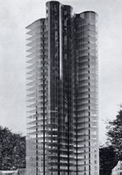
Figure 7. All-glass office buildings, conceived (but never constructed) by architect Mies van de Rohe in 1919 (left) and 1921(right).
The metal and glass curtain wall became a feature of some of the seminal works of the International Style that dominated world-wide design after World War II. Le Corbusier's Pavilion Suisse, Paris (Figure 8A) designed in 1929 was one of the most influential. The most significant development of the curtain wall, however, occurred in the United States. First designed as an expensive, refined and elegant custom artifact, it gradually became a standard commodity, and today is the least costly way to enclose a structure. Perhaps more important, for several decades the glass box perfectly symbolized, in its image of contemporary elegance and modernity, the aspirations of American corporate architecture from Wall Street to Main Street. The United Nations building of 1947 (Figure 8B) and the Lever Brothers building of 1952 (Figure 8C) had enormous impact on architects and owners alike. Within a few years every city in the U.S. had its blue, glass-curtain walled cubes, from corporate headquarters to modest savings and loan branches (Figure 8D). Today, very refined custom walls are still being conceived that can demonstrate an extraordinary scale and delicacy (Figure 9).


Figure 8. Curtain wall development: (clockwise from top-left) 8A Pavilion Suisse, Paris, Le Corbusier, 1930; 8B United Nations Secretariat, New York, Architectural Consortium, 1950; 8C Lever House, New York, Skidmore Owings and Merrill, 1952; 8D Curtain wall office building, any city, USA 1965–1985.
Many problems, such as leakage and obtaining pleasing glass colors, had to be solved in early curtain walls. Manufacturers and influential architects working together managed to do so. The first curtain walls were expensive, custom-made assemblies. The proprietary curtain wall has now evolved into the least expensive way of cladding a building. However, very refined custom walls are still being conceived that can demonstrate an extraordinary scale and delicacy. (Figure 9)

Figure 9. Suspended curtain wall, AOL/Time Warner building, New York, 2003. James Carpenter, glazing consultant; Skidmore, Owings and Merrill, Architects.
Future innovations still in their infancy are the double-skin curtain wall that aims to provide controlled natural ventilation and hybrid systems that aim to achieve substantial energy savings as a hedge against an uncertain energy future. (Figure 10)
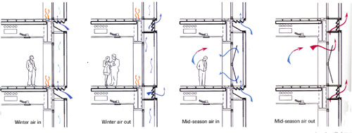
Figure 10. Hybrid mechanical and natural ventilation with double skin façade. Minerva Tower, London. Nicholas Grimshaw, Architect; Roger Preston & Partners, services engineers.
Conclusion
A number of categorizations of the systems or subsystems that comprise a building are in existence. Richard Rush, in his book The Building Systems Integration Handbook, defined only four systems:
- Structure
- Envelope
- Mechanical
- Interior
Thus the systems and assemblies of the envelope are one of the four main parts of the building both in terms of their physical existence and in their contribution to overall building performance. The envelope protects the other systems from harsh aspects of the outside. It also works in conjunction with the other systems to ensure a safe and benign environment for the building occupants. Thus the envelope is a gatekeeper, allowing certain aspects of the exterior into the building, rejecting some and changing the nature of others. The design of the envelope is very complex and many factors have to be evaluated and balanced to ensure the desired levels of thermal, acoustic and visual comfort together with safety, accessibility and aesthetic excellence.
This guide provides information and recommendations to assist the designer in achieving their goals. While levels of performance are discussed and many quantitative criteria are explained, no mandatory requirements are stated. Those are the purpose of building codes and regulations. This guide assumes that any design work will conform to code requirements but deal also with many functions that, while not subject to code, are essential for building excellence.
Building Information Modeling (BIM)
Introduction
Within This Page
A Building Information Model (Model) is a digital representation of physical and functional characteristics of a facility. As such, it serves as a shared knowledge resource for information about a facility forming a reliable basis for decisions during its life cycle from inception onward.
A basic premise of Building Information Modeling is collaboration by different stakeholders at different phases of the life-cycle of a facility to insert, extract, update or modify information in the Model to support and reflect the roles of that stakeholder. The Model is a shared digital representation founded on open standards for interoperability.
Some have identified BIM as dealing with only 3D modeling and visualization. While important and true, this description is limiting. A more useful concept is that a Model should access all pertinent graphic and non-graphic information about a facility as an integrated resource. A primary goal is to eliminate re-gathering or reformatting of facility information; which is wasteful.
Non-value added effort or waste is a significant problem in the construction industry. Much of the waste comes from inaccurate or entrusted information causing the information to have to be re-gathered multiple times throughout the life of the project. This waste has been identified to be 57% in the construction industry by a chart prepared by the Construction Industry Institute and Lean Construction Institute. While waste in the manufacturing sector was identified to be 26%. This 31% variance when plotted against the 2008 design and construction spending projections by Engineering News-Record comes out to nearly $400B annually. This number does not include operations and sustainment, which would jack the number up through the ceiling, as if it were not high enough already. The primary beneficiary is the owner. However, many owners seem to be content to pay the freight of design and construction, whatever the cost and have been rather lethargic to push for change to date. The construction industry, however is seeing benefit to implementing BIM on their own and is pushing forward at a rather rapid rate for this traditionally conservative industry.
BIM standards have many objectives but one of the most important is to improve business function so that collection, use and maintenance of facility information is a part of doing business by the authoritative source and not a separate activity.
The scope of BIM is from the smallest part rolled up to the world or portfolio view, from inception onward in the lifecycle of a facility and includes all stakeholders that need facility information from the designers to the occupants.
Numerous organizations have initiatives underway to develop a National BIM Standard. The following sections provide links and describe the efforts underway to develop a standard for information sharing that will help weave all stakeholders into a common fabric.
Relevant Codes and Standards
- National BIM Standard-United States® (NBIMS-US™) by the National Institute of Building Sciences, 2015. The NBIMS-US™ provides consensus based standards through referencing existing standards, documenting information exchanges and delivering best business practices for the entire built environment. The National Institute of Building Sciences BIM Council, through the NBIMS-US Project, works to establish the standards needed to foster innovation in processes and infrastructure so that end-users throughout all facets of the industry can efficiently access the information needed to create and operate optimized facilities.
Major Resources
Government Initiatives
- Tri-Service CAD BIM Technology Center The CAD/BIM Technology Center explores new CAD and BIM technologies for facilities, infrastructure, and environment within DoD.
- Naval Facilities Engineering Command (NAVFAC) Building Information Management and Modeling (BIM) The Navy is the first federal government agency to leverage Building Information Management and Modeling (BIM) to acquire Facility Electronic Operation and Maintenance Support Information (eOMSI).
- Air Force Building Information Modeling for MILCON Transformation The Air Force is utilizing the BIM environment to meet its MILCON Transformation goals and objectives.
- Defense Health Agency (DHA) Building Information Modeling (BIM) The Military Health System (MHS) was the first healthcare system in the U.S. to implement the use of BIM across the facility lifecycle.
- General Services Administration (GSA) GSA was the first government organization to lead the U.S. government into BIM and had a primary role in promoting BIM in the entire industry. They remain today a leader in the initiative, continually breaking new ground.
- Department of Veterans Affairs (VA) VA is committed is committed to utilizing BIM to support the delivery and management of world-class healthcare for our nation's veterans.
Building Integrated Photovoltaics (BIPV)
Introduction
Within This Page
Photovoltaic (PV) technology is an ideal solution for the electrical supply issues that trouble the current climate-change, carbon-intensive world of power generation. PV systems can generate electricity at remote utility-operated "solar farms" or be placed directly on buildings themselves. Their fuel source is simple sunlight, and they produce electricity without the negative environmental consequences associated with other power generation methods. They are silent and reliable. The size of PV installations can range from extremely small to enormously large. They can be scaled down for small loads like specific site luminaires, remote communication devices, and individual water pumps; or they can occupy hundreds of acres and generate enough electricity to power thousands of buildings.
For building installations, PV systems fall into two categories, building applied photovoltaics (BAPV) and building integrated photovoltaics (BIPV). BAPV is the more common type of installation, with the solar collectors located completely outside of the building envelope. Roof-mounted, ballasted solar arrays placed on top of the roofing material are BAPV assemblies. A BIPV installation is when the photovoltaic collectors are an integral part of the building envelope. They can either replace exterior shell components or be integrated into them. Examples of BIPV components and materials currently on the market include: PV glass windows, PV glass skylights, awnings, balustrades, canopies, shingles, exterior wall panels, and even PV walkable surfaces.1 Not only do BIPV systems generate electricity, but they can add visual interest and aesthetic design elements to the building.
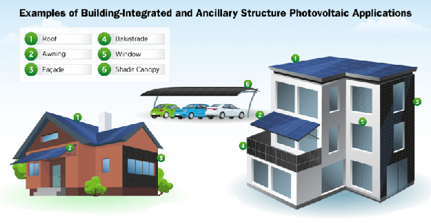
Building Integrated Photovoltaics (BIPV) are when the photovoltaic collector elements are located directly within a building's envelope (or canopy structure). Photo Credit: U.S. Department of Energy / EERE
Building owners and utilities all benefit with the implementation of PV systems. The contribution of PV generated electricity can have major impacts on the peak demand loads that utilities have to provide power for. Late afternoon sunshine and heat accumulation in buildings lead to greater requirements placed on air conditioning systems to keep occupants cool. A building-located photovoltaic system takes advantage of these same sunshine conditions to provide electricity for the building while simultaneously lessening the pressure on the utility grid to increase electricity production. The use of photovoltaics lowers the overall U.S. carbon footprint for electricity generation.
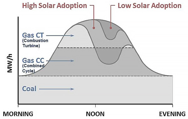
Solar energy installations have an impact on the fuel sources used by utilities to generate electricity for the grid. As PV generated power increases in the energy infrastructure, the use of higher carbon-footprint generated electricity decreases. Image Credit: Ronald Fergle based on a graphic by Lena Hansen and Virginia Lacy of the Rocky Mountain Institute
A building's self-consumption of the electricity generated by its PV system improves the cost-effectiveness of the installation. Buying electricity from the grid costs more than revenue achieved by selling electricity to the grid. Utilizing batteries to store PV electricity for later use can dramatically reduce the need for grid-supplied electricity. The potential for including battery storage in a PV system design should take into consideration the building loads, the time of day, the available PV generated power, and the costs for various levels of battery storage. Properly sized systems can be cost-effective for consumers.
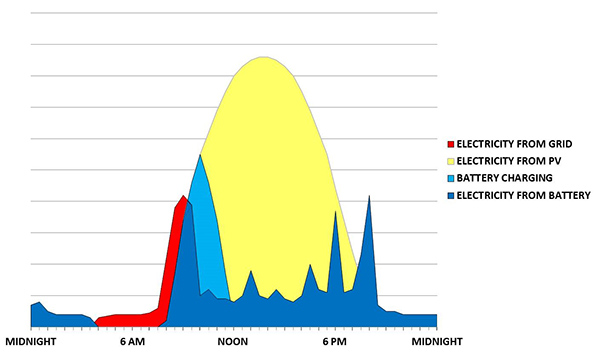
The self-consumption of PV generated electricity coupled with battery storage can significantly reduce the need for grid-supplied electricity. Image Credit: Ronald Fergle based on a graphic by Ralf Haselhuhn.
Depending on the fuel source, generation of electricity at a utility power plant can be inefficient and carbon-intensive, while simultaneously causing the release of Greenhouse Gasses (GHGs) and harmful fine Particulate Matter (PM2.5). In addition, of the electricity that enters the grid from a power plant, the U.S. Energy Information Agency (EIA) estimates that 5% is lost due to transmission and distribution (T&D) inefficiencies.2 Distributed Energy Resources (DERs) such as BIPV systems, do not have these negative environmental impacts. Solar energy is a clean, renewable energy source, and the electricity generated is already located at the point of use. For more information regarding Distributed Energy Resources, refer to the energy.gov website.
Description
Photovoltaic Technologies
The categories of common photovoltaic technologies used in BIPV applications include:
Crystalline silicon (c-Si): Solar cells made from solid crystalline silicon wafers (mono-crystalline or poly-crystalline/multi-crystalline) can deliver approximately 20 watts per ft2 of PV array. Versions of these cells may incorporate additional layers of solar absorption materials in order to increase electrical production. Individual cells are wired together and assembled into modules at factories before being shipped to project sites.
Thin-film: These products typically incorporate very thin layers of photovoltaic compounds that have been deposited on substrate materials using plasma enhanced, chemical vapor deposition (PECVD) processes. Commercial thin-film materials deliver about half the watts per ft2 of PV array area compared to c-Si modules. Thin-film products can be rectilinear modules, rolled-out surfaces, or take the shape of an underlying architectural element. This category includes: copper indium gallium (di)selenide (CIGS), cadmium telluride (CdTe) and amorphous silicon (a-Si) cells.
Emerging-PV: These technologies include dye-sensitized solar cells (DSSC), Perovskite cells, organic cells, and quantum dot cells, among others. Efficiencies in laboratory environments range from 13% to 26%. Cells in this category can exhibit properties of transparency, flexibility, or color; and they require lower energy expenditures to create.
The DSSC cells represent a new type of solar cell that require less energy-intensive materials to manufacture, and because of their simplicity can be less costly to produce. These cells are comprised of three basic parts: the front-side glass transparent conducting oxide (TCO) electrode, an interior electrolyte solution, and a back-side counter electrode. The inside surface of the front glass is first sintered with a transparent anode, e.g., fluoride-doped tin dioxide (SnO2:F) to make the TCO. Then it is covered with titanium dioxide (TiO2) nanoparticles coated with photo-sensitive dyes. When the dyes are exposed to sunlight their electrons are energized and elevated into the conduction band of the TiO2. From there they migrate to the TCO anode material. After flowing through an external circuit as electricity, the electrons re-enter the DSSC cells through a back-side counter electrode surface. The liquid electrolyte then transports the electrons back to the dye materials to re-oxidize them.
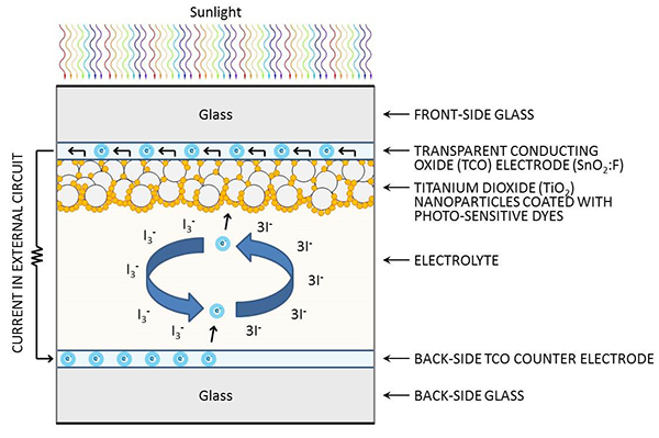
A schematic showing the movement of electrons in the DSSC photovoltaic process. Image Credit: Ronald Fergle
A PV installation includes:
PV Modules: These "solar collectors" can be crystalline, thin-film, or one of the emerging PV technologies. They can be transparent, semi-transparent, or opaque.
- Balance of System (BOS) Components: This includes everything in a PV installation other than the solar collectors.
- Module Mounting Systems
- Wiring, Combiner Boxes, DC Disconnects, and AC Disconnects
- Inverters
- Electrical Distribution Panels
- Batteries
PV Modules: These components are where the conversion of sunlight into electricity actually occurs. Energetic photons in sunlight excite electrons in the semi-conductor materials which elevate them to a higher energy conduction band. The electrons then become free to move as electricity within an external circuit. The electricity coming from PV modules is always Direct Current (DC).
Module Mounting Systems: BIPV mounting systems use clips, bolts, or adhesives to fix the modules directly to the envelope structure. Photovoltaic glass units for façade or roof applications are installed similarly to windows or skylights, but with DC cabling attached. For BAPV installations these systems usually consist of metal frameworks called racking. They can be constructed to create fixed, saw-tooth arrangements or flat planes that are located close to the roofing surface. Typically weights or heavy blocks are used to secure the racking in place.
Wiring, Combiner Boxes, DC Disconnects, and AC Disconnects: These are the components that facilitate and address the flow of electricity in the installation. Individual wiring from groups of modules can be combined into single cables in combiner boxes for circuit simplicity and to reduce the overall amount of wiring material. Combiner boxes also provide over-current protection. DC Disconnects and AC Disconnects are switches located at strategic points in the installation in order to disconnect or curtail the flow of electricity.
Inverters: These units convert the DC electricity coming from the PV modules into AC electricity. String invertors handle the output from multiple modules, and micro-inverters are dedicated to a single module.
Electrical Distribution Panels: This is the location where PV installations interconnect with a building's electrical infrastructure. Power coming from the PV system is wired into the distribution panelboard as an individual circuit. The circuit breaker on this circuit is referred to as the Over Current Protection Device (OCPD) and subject to specific sizing requirements.
Batteries: These devices store power for use at a later time. The energy flow into and out of the battery storage system is determined based on user-specified parameters or building energy management system (BMS) directives. Batteries are commonly used to store power generated from the PV array during sunny periods, and then provide that power later on to help meet the facility's energy requirements.
For more detailed information on PV module technologies and BOS Components, refer to the related discussion on the WBDG PV page.
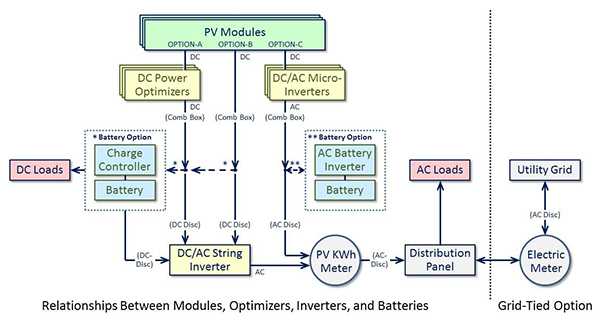
A simplified guide for how PV modules can be connected to power optimizers, string inverters, or micro-inverters based on system design objectives. (System schematics, including combiner boxes and disconnect switches, vary based on project parameters and equipment used.) Image Credit: Ronald Fergle
Building Integrated Photovoltaics (BIPV) System
Building Integrated Photovoltaics is the implementation of photovoltaics as part of the building envelope. The solar collectors serve the dual function of protecting the structure from external environmental conditions, as well as being a source for electrical power. While the BIPV system itself has an initial financial cost, because it potentially replaces other building materials the overall costs of the envelope may not increase significantly. BIPV systems can also reduce HVAC electrical requirements and cooling costs when the modules are used to shade the building. When all of the advantages are taken into consideration, BIPV installations can be viewed as financial investments. They have an up-front cost, but in turn they can significantly reduce or eliminate a building's yearly energy costs, pay for themselves, and provide building owners with continuing economic savings. A recent study has documented how BIPV installations have a positive return-on-investment (ROI), and even north-facing facades can be economically feasible.3
Design Of A Building Integrated Photovoltaics (BIPV) System
The process of designing a BIPV system is not unlike that for other building systems. Decisions should take into consideration life-cycle cost analyses in addition to up-front costs, installation procedures, performance expectations, and O&M requirements. However, with BIPV installations the aesthetics are also important and should be taken into account.
Steps in designing a BIPV system overlap, in that the consideration of one topic may impact the resolution for another. A successful solution addresses all concerns simultaneously. The general list of topics includes:
- Energy Conscious Building Design: This strategy reduces overall energy use, enhances comfort, and saves money while also enabling the BIPV system to provide a greater percentage of the electricity required.
- Daylighting: The use of sunlight and light from the skydome to illuminate interior building spaces. This reduces the electrical loads and heat generated from light fixtures.
- Thermal Mass: Taking advantage of a material's ability to store and release heat energy in order to even out interior building temperature fluctuations.
- Natural Convection: Using the natural properties of air circulation to ventilate, heat, or cool interior building spaces.
- Type of PV System: Determine if the system will be grid-connected, grid-connected with battery backup, or stand-alone.
- The majority of BIPV systems are tied to a utility grid, which in effect uses the grid as storage and backup. The system type and configuration should be developed based on the priorities of the owner, which could include: budget limitations, space constraints, electrical requirements, energy independence, and aesthetics, among others.
- For stand-alone systems powered by PV alone, the system, including battery storage, should be sized to meet both the building's peak demand loads and the lowest power production projections of the PV array. Installations like these typically include a backup generator for unusual or excessive peak loads.
Location of Installation: Any exterior building surface is a potential location for a BIPV installation. Roof elements include: photovoltaic shingles, rolled thin-film surfaces, and PV glass skylights that have PV cells or transparent PV surfaces incorporated into them. Wall possibilities include: siding with integrated PV surfaces, PV glass windows that contain PV cells or PV coatings, and shading devices that are also PV collectors. Railings, carports, and covered entryways are additional locations. As part of the PV component selection process it is important to consider how the collector surfaces will be attached to the sub-structure. Manufacturers of PV components provide detailed information regarding mounting requirements.
Building Electrical Load Analysis: Consider the building's electrical usage patterns and adjust loads if possible to reduce peak levels. Depending on the building type (or functions occurring within the structure), shifting when power is required can reduce demand spikes and the peak loads they place on the PV system. Examples of flexible tasks include: meetings that require lighting and space conditioning, optional machinery processes, operation of dishwashers or laundry facilities, and heating of hot water for thermal storage. Electrical demands are typically greater in the afternoon because of HVAC cooling loads, so when non-time-sensitive tasks can be moved to the morning hours, the peak afternoon loads become less. Installing motion detectors on lighting systems and turning off office equipment when not in use are simple strategies to reduce power demands. It has also been shown that educating building occupants about the benefits of reducing plug-loads helps to achieve lower energy use.4 In addition, it may be worthwhile to incorporate battery storage to reduce the purchase of electricity during the more expensive power demand periods.
Provide Adequate Ventilation: PV performance efficiencies are reduced by elevated operating temperatures. This affects crystalline silicon PV cells more than amorphous silicon thin-films, but all PV cells are susceptible. To improve conversion efficiency, allow appropriate ventilation behind the modules in order to dissipate heat.
Consider Using PV Modules to Filter Direct Sunlight: When using semi-transparent thin-film modules or semi-transparent crystalline modules (where the PV cells are placed apart from each other between two layers of glass), it is possible to create unique daylighting features in facades, roofing, or skylight PV systems. These elements can help reduce unwanted cooling loads and the glare associated with large expanses of architectural glazing.
Incorporate PV Modules as Shading Elements: PV arrays can double as awnings over view-glass areas of buildings and can provide appropriate shading. When sunshades are considered as part of an integrated design approach, chiller capacity can often be smaller and perimeter cooling distribution reduced or even eliminated.
- Design for the Local Climate and Environment: It is important to understand the impacts of climate and environment on the array output. Cold, clear days will increase power production, while hot, overcast days will reduce array output. Typical considerations include:
- Surfaces reflecting light onto the array (e.g., snow, lakes, or wide rivers) will increase the array output.
- Potential snow- and wind-loading conditions may require additional bracing or structural analysis.
- Modules angled more vertically will shed snow quicker.
- Horizontal modules and arrays located in dry, dusty environments, or environments with heavy industrial traffic or pollution, will require periodic rinsing with water to limit efficiency losses.
- c-Si modules have higher efficiencies and perform best in clear sky conditions, but their power output decreases significantly in cloudy or shady situations. While DSSC, CdTe, a-Si, and CIGS cell types have lower efficiencies compared to c-Si, they are less affected by cloudy or overcast conditions.
Address Site Planning Issues: Early in the design phase, ensure that the solar array will receive maximum exposure to the sun and will not be shaded by site obstructions such as nearby buildings or trees. It is important that the system be unshaded during the peak solar collection period consisting of three hours on either side of solar noon. The impact of shading on a PV array can be significant.
Consider Array Orientation: Array orientation and tilt impacts the annual energy output of a system. Arrays tilted towards the Sun generate 50%–70% more electricity than vertical façade installations, and southern facing arrays maximize power generation. However, advancements in PV technologies have increased the flexibility of array design; so it may be possible to tune the electrical output of a system to be closer to the time of day the power is required. Certain module types may be more effectively used facing east for the morning solar gain, or west for the late afternoon sunlight conditions (CdTe, CIGS, DSSC, and a-Si thin-films), and high-gain modules (typically c-Si) can be aligned slightly west of south so they produce more electricity during the afternoon peak building demand loads. As the costs for PV installations continue to decrease, the strategy to provide more continuous power generation becomes more affordable. Portions of arrays that are oriented to the east or west may not be as high in efficiency or produce the sheer volume of electricity that the southern facing portions do, but they can provide additional power closer to the time that some building loads require it.
Use Credentialed Professionals: Ensure that the designers, installers, and maintenance professionals involved with the project are properly trained, licensed, certified, and experienced in PV systems work. They should be knowledgeable of the latest advancements in commercially available technologies, products, and installation practices.

Solar insolation levels can vary based on building surface orientation. While surfaces tilted towards the Sun receive the most energy, secondary and tertiary surfaces can still contribute meaningful amounts of PV generated electricity. Image Credit: Ronald Fergle based on a graphic by Polysolar Ltd.
Application
BIPV systems can be designed to blend in with traditional building materials and appearances, or they may be used to create a more innovative aesthetic. The examples below show how PV modules can become attractive elements of building exteriors. Photovoltaics may be integrated into numerous assemblies within building envelopes, including:
Facades: Solar cells can complement or replace traditional view windows or spandrel glass. While these installations are on vertical surfaces, which reduce the intensity of the solar insolation, the overall size of a facade can help compensate for the reduced power per unit area.
Awnings: Photovoltaics may be incorporated into awnings or slightly sloped, saw-tooth canopy designs. Semi-transparent modules provide filtered sunlight underneath while affording additional architectural benefits such as passive shading.
Roofing: The use of PV in roofing systems can provide a direct replacement for batten and seam metal roofing, traditional 3-tab asphalt shingles, and ceramic tiles. Note that these types of installations require adequate ventilation in order to keep the cell temperatures cooler.
Skylights: Using PV for skylight systems can be both an economical use of PV and an interesting design feature. Just as with PV windows, the semi-transparency enables visual connections to the exterior environment while providing diffuse natural lighting.
An example of the aesthetic potential of BIPV is the SwissTech Convention Center (STCC) on the Ecole Polytechnique Federale de Lausanne (EPFL) Ecublens, Switzerland, campus. The southwest façade contains 280 m2 of 355 integrated Die-Sensitized Solar Cells (DSSC), also called Grätzel cells, arranged within 65 columns of various heights. The system provides 3 kWp of electricity. The transparent DSSC installation filters direct afternoon sunlight entering the convention center main lobby; while at the same time providing a visual connection to the exterior environment with views to the sky, neighboring buildings, trees, and passersby.

Exterior views of the SwissTech Convention Center southeast façade (left) and southwest façade (right). Photo Credit: Ronald Fergle

Interior views of the DSSC modules exhibit a canvas of translucent vertical ribbons of color with the blue sky in the background. As the sun progresses through the sky, the colorful shadows cast from the modules move across the lobby floor. Photo Credit: Ronald Fergle

The light-weight modules are mounted to metal bars on the exterior side of the window glazing. The electrical cabling runs within channels next to the windows. Photo Credit: Ronald Fergle
Examples of c-Si wafers being used in innovative ways include the Energiewürfel building in Konstanz, Germany, and the Ludesch Community Centre in Vorarlberg, Austria. The modules have dual-glass surfaces with individual, perforated c-Si wafers spaced evenly inside. The installations filter direct sunlight while simultaneously providing views beyond. The Energiewürfel large-format, south-facing window installation has a 22% transparency, and when combined with the PV roof installation generates 23.2 kWp of electricity. The 350 m2 Ludesch Community Centre canopy is comprised of 120 slightly-sloped modules oriented to the southwest, and generates 16,000 kWh/yr of electricity. The canopy emphasizes the exterior gathering area while protecting visitors from rain and snow.
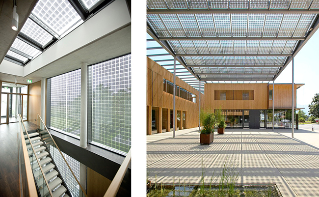
Semi-transparent module installations in the Energiewürfel building in Konstanz, Germany, (left) and the Ludesch Community Centre "town square" plaza in Vorarlberg, Austria (right). Photo Credit: Sunways AG
The Beit Havered building near Tel Aviv, Israel, has a photovoltaic façade composed of crystalline silicon glass with white digital printing on the surface. The printing provides a more traditional appearance while allowing the solar energy to pass through to the PV cells behind. The 608 m2 installation is estimated to generate 1,938,623 kWh of electricity over 35 years, with avoided CO2 emissions of 1,409 Tons of CO2. The system payback period is less than 4 years.

The Beit Havered building's façade of c-Si PV glass with white digital printing on the surface provides a more traditional commercial/office building aesthetic. Photo Credit: Onyx Solar
The Paul Horn Arena in Tübingen, Germany, is comprised of PV modules designed to be both attractive and efficient power generators. The aesthetics take advantage of the emerald-green "fractured" multi-crystalline silicon cell appearance mounted within oversized white rectangular frames. The unobstructed, 530 m2 installation receives continuous solar insolation throughout the day. The system generates 43.7 kWp of electricity.

The south façade of the Paul Horn Arena in Tübingen, Germany. Photo Credit: Sunways AG
The Life Sciences Building (LSB) at the University of Washington has a 650 m2 20% transparent amorphous silicon (a-Si) vertical fin BIPV installation on the southwest curtain wall. The photovoltaic fins generate 3.15 W/ft2, and over their 35 year lifespan are estimated to provide 496,885 kWh of electricity with a CO2 avoidance of 333 Tons of CO2.

The southwest façade of the Life Sciences Building (left) and a close-up of the semi-transparent fins (right). Photo Credit: Onyx Solar
The Frank Gehry designed Novartis Campus building in Basel, Switzerland, exhibits the freeform potential of BIPV. The envelope contains a combination of dual-glass PV skylights and PV window modules with imbedded, perforated PV cells. The 1,300 m2 PV installation provides 92 kWp of electricity.

The Novartis Campus building southern façade (left) and outward view from the interior (right) show that photovoltaic systems do not need to dominate a building's aesthetic to be effective. Photo Credit: Sunways AG
Relevant Codes and Standards
- IEEE 1547 Standard for Interconnecting Distributed Resources with Electric Power Systems
- Inflation Reduction Act of 2022 (IRA) and the EPA summary
- International Code Council (ICC) 690.12
- NFPA 70 National Electrical Code (NEC) Article 690.12
- UL 1703 Standard for Flat-Plate Photovoltaic Modules and Panels
- UL 1741 Standard for Inverters, Converters, Controllers and Interconnection System Equipment for Use With Distributed Energy Resources
Publications
- Building-Integrated Photovoltaic Designs for Commercial and Institutional Structures: A Sourcebook for Architects
- Building-Integrated Solar Technology, Roland Krippner (Ed.), Detail Business Information GmbH, Munich, DE, www.detail.de, ISBN 978-3-95553-362-5 (Print), ISBN 978-3-95553-363-2 (E-Book), ISBN 978-3-95553-364-9 (Bundle)
- The SwissTech Convention Center, Richter Dahl Rocha & Associés architects SA, Editions Favre SA, Lausanne, ISBN 978-2-8289-1480-6
Additional Resources
Websites
- Database of State Incentives for Renewables & Efficiency (DSIRE), provides a comprehensive list of federal, state, and local incentives that promote renewable energy and energy efficiency.
- DOE's EERE Solar Photovoltaics Technology Basics, gives a brief description of how the photovoltaic materials convert sunlight into electrical energy.
- National Center for Photovoltaics (NCPV), focuses on innovations in photovoltaic technology that drive industry growth in photovoltaic manufacturing nationwide. Formed by the U.S. Department of Energy (DOE) and based at NREL, the NCPV focuses on research and development and increasing U.S. competitiveness.
- North American Board of Certified Energy Practitioners (NABCEP), provides an industry certification of experienced photovoltaic installers. NABCEP was designed to raise industry standards and promote consumer confidence in photovoltaic and solar thermal system installations.
- Procuring Solar Energy: A Guide for Federal Facility Decision Makers , provides an overview for federal facility managers and their procurement terms, for the process of installing solar electric and solar thermal systems.
- Sandia National Laboratories, works with the U.S. Department of Energy, industry, and academia to improve the performance and reliability of photovoltaic technologies and grid integration.
Computer-Based PV Design and Sizing Tools
- HOMER—Hybrid Optimization Model for Electric Renewables (HOMER) is a design optimization model that determines the configuration, dispatch, and load management strategy that minimizes life-cycle costs.
- NREL's PVWatts calculator—Determines the energy production and cost savings of grid-connected photovoltaic energy systems throughout the world.
- PV F-Chart—Provides analysis and rough sizing of both grid-connected and stand-alone PV systems.
- PVFORM—Offers simulation of grid-connected and stand-alone systems, including economic analysis. Available from Sandia National Labs, Albuquerque, NM.
- TRNSYS—Simulation system for renewable energy applications; originally for solar thermal, now has extensions for PV and wind.
Other
- Solar-Estimate.org is a free public service offering solar estimating tools and is supported by the Department of Energy and the California Energy Commission.
Training Courses
Endnotes
1 Onyx Solar, Products and Services.
2 U.S. Energy Information Administration, Frequently Asked Questions (FAQS).
3 "Economic analysis of BIPV systems as a building envelope material for building skins in Europe", by Hassan Gholami and Harald Nils Røstvik; Department of Safety, Economics and Planning, University of Stavanger, Kjell Arholmsgate 41, 4036, Stavanger, Norway.
4 "Sustainability in Practice, Building and Running 343 Second Street, The Packard Foundation Headquarters", by Robert H. Knapp, Physics and Sustainable Design, Evergreen State College.
Building Materials and Furnishings Sustainability Assessment Standards
Introduction
Within This Page
A growing number of manufacturers of building materials and furnishings are leading the industry in moving toward improved product sustainability. To help achieve this mission, sustainability assessment standards have been developed across a broad range of product categories to assist manufacturers in identifying strategies and communicating improved performance. The standards often include relevant criteria across the product's life cycle, i.e. from growth phase of renewable materials, raw material extraction, manufacturing, use, and end-of-life management. Through multiple levels of achievement, many of these standards are providing an incentive for manufacturers to continue reducing the environmental impacts of their products and providing a way for designers and specifiers to distinguish among industry leaders.
Description
The purpose of sustainability assessment standards is to provide a thorough communication of information that is verifiable, accurate, and not misleading about the environmental and social aspects associated with the production and use of building materials and furnishings. Such communication is expected to encourage the demand for and supply of products that cause less stress on the environment and society, thereby stimulating the potential for market-driven continuous improvement. Private and public sector interests have encouraged manufacturers to improve the environmental performance of and provide environmental impact information on the products they produce.
These standards are intended to be science based, provide transparency, and offer credibility for manufacturers in making claims of environmental preferability and sustainability, and to harmonize the principles and procedures used to support such claims. These standards provide a practice for assessing the sustainability of building materials and furnishings. Sustainability-related information can inform a manufacturer's decisions about supply chain modifications, product(s) content changes, manufacturing adjustments, performance improvements, end-of-life options, and corporate governance, with the goal of producing more sustainable products.
Sustainability assessment standards also provide a means to track incremental changes to the products' sustainability profile. These standards are intended to provide a consistent framework in which to compare and assess the sustainable nature of different products that perform similar functions.
Trends in the criteria of sustainability assessment standards include:
- Multi-attribute assessment of the product/product category of interest
- Life-cycle based consideration of the product/product category of interest
- Science-based, verifiable criteria
- Assessment of corporate governance and social responsibility indicator reporting
- Product performance assessment as baseline criteria
- Consideration of relevant international criteria, or is adaptable to international markets
Most sustainability assessment standards have been designed, in part, to satisfy the following criteria:
Product design, encouraging manufacturers to integrate environmental and life-cycle thinking into the product(s) design process.
Product manufacturing, encouraging manufacturers to quantify the environmental impacts from their manufacturing, and then act to reduce or remove those impacts.
Long-term value, encouraging manufacturers to maximize product(s) longevity.
End of life management, ensuring that existing and new resilient flooring products can be collected, processed, recycled, and/or composted within the existing materials recycling infrastructure.
Corporate governance, encouraging corporate social responsibility in the forms of providing a desirable workplace, being involved in the local community, and demonstrating financial health.
Innovation, to give manufacturers the opportunity to be awarded points for exceptional performance above the requirements set forth in the standard.
| Standard Data Elements | Carpet NSF 140 | Textile NSF 336 | Furniture BIFMA e-3 | Wallcoverings NSF 342 | Resilient Flooring NSF 332 | Single Ply Roofing NSF 347 | Laminate Flooring NALFA LF 02 | Ceramic Tile ANSI A138.1 | Gypsum Board UL 100 | Swinging Door UL 102 |
|---|---|---|---|---|---|---|---|---|---|---|
| Product Content | ✔ | ✔ | ✔ | ✔ | ✔ | ✔ | ✔ | ✔ | ✔ | ✔ |
| Health & Environment | ✔ | ✔ | ✔ | ✔ | ✔ | ✔ | ✔ | ✔ | ✔ | ✔ |
| Energy | ✔ | ✔ | ✔ | ✔ | ✔ | ✔ | ✔ | ✔ | ✔ | ✔ |
| Recycling / Reclamation | ✔ | ✔ | ✔ | ✔ | ✔ | ✔ | ✔ | ✔ | ✔ | ✔ |
| Water Conservation | ✔ | ✔ | ✔ | ✔ | ✔ | ✔ | ✔ | ✔ | ✔ | ✔ |
| Air Quality | ✔ | ✔ | ✔ | ✔ | ✔ | ✔ | ✔ | ✔ | ✔ | ✔ |
| Social Responsibility | ✔ | ✔ | ✔ | ✔ | ✔ | ✔ | ✔ | ✔ | ✔ | ✔ |
| Innovation | ✔ | ✔ | ✔ | ✔ | ✔ | ✔ | ✔ | ✔ |
ANSI Requirements for Voluntary Consensus Standards
An ANSI-accredited voluntary consensus standards body follows a process with the following attributes:
- Openness to all impacted stakeholders and interested parties;
- Balance of diverse interests and participation by all impacted stakeholders;
- Due process allowing for the expression of positions and their basis, and the consideration of all positions;
- A readily available and impartial appeals process;
- Consensus, which is defined as general agreement, but not necessarily unanimity, and includes process for attempting to resolve objections by interested parties, as long as all comments have been fairly considered, each objector is advised of the disposition of his or her objection(s) and the reason why, and the consensus body members are given the opportunity to change their votes after reviewing the comments
Certification
Once a sustainability assessment standard has been published there are several ways in which products can be certified as meeting the requirements contained in the standard including:
Self-Certification
A product manufacturer may choose to certify that its product meets the requirements in a standard to achieve a specified achievement level. They simply provide a statement or certificate stating the product meets the standard requirements. The value or strength of this type of certification is solely based on the reputation of the product manufacturer.
2nd Party Certification
An association, to which the product manufacturer belongs, provides the assurance for this certification. It is the responsibility of the association to monitor and assure the quality of the individual members to ensure the reputation of the product association.
3rd Party Certification
A third party provides the certification, which is completely independent from the product manufacturer, contractor, designer, and specifier. Third party certifications are the more trusted form of environmental conformance verification since they require the hiring of an outside auditing firm. Although they are the most expensive type of certification, third party certifications can be very helpful because they validate the product meets industry independent standards. They also provide assurance to specifiers, building owners, designers, and consumers that the product manufacturer's marketing claims are accurately stated.
Application
These standards are intended to be used primarily by product(s) manufacturers interested in understanding the sustainability performance of their product(s). Independent auditors, certification bodies, and environmental labeling organizations are also potential users of these standards for their use in supporting market-based environmental and sustainability claims. These standards may also be used by purchasers and consumers who wish to ensure that manufacturers are accurately declaring the sustainable nature of their products. These standards can be used where building materials and furnishings are being specified for green commercial, industrial, and residential buildings.
Additionally these standards can be used as part of government programs that identify products which exhibit reduced impacts on the environment.
The National Technology Transfer and Advancement Act of 1995 (NTTAA) directs federal agencies to use voluntary consensus standards, in lieu of government-unique standards, in procurement and regulatory activities, unless use of such standards would be inconsistent with applicable law or otherwise impractical. Office of Management and Budget (OMB) Circular A-119 implements the NTTAA and defines standards and voluntary consensus standards for the federal community. OMB A-119 does not establish a preference between consensus and non-consensus standards developed in the private sector. In general, A-119 provides broad discretion to individual agencies in determining if/how to make use of non-governmental standards. This provides agencies with the flexibility to select standards that best meet their needs.
Various laws and parts of the Federal Acquisition Regulation (FAR) require that agencies purchase environmentally sustainable products and services. All GSA employees are responsible for complying with the GSA Green Purchasing Plan (GPP) . The General Services Administration (GSA) currently references several sustainability standards in PBS-P100 Facilities Standards for the Public Buildings Service.
The Collaborative for High Performance Schools (CHPS) references several sustainability assessment standards in the Environmentally Preferable Products section of their Best Practices Manual.
The ICC-700 National Green Building Standard references several sustainability assessment standards in the Innovative Practices section. (See also Green Building Standards and Certification Systems.)
ISO Principles for Third-party Conformity Assessment Programs
Conformity assessment refers to the procedures and practices used to determine whether a product conforms to the requirements of a standard and/or ecolabeling program. In order to instill confidence among specifiers Type 1 independent third party certification programs developed in accordance with the principles of ISO 14024 have been established for a growing number of voluntary consensus product sustainability assessment standards. These certification programs are typically distinguished by adherence to the following principles:
- Independence in auditing processes and decision making
- Accessibility to interested parties
- Involvement of a balance of interests in management of the program
- Process for the management and resolution of complaints and appeals
- Accreditation as an independent third party certifier under ISO Guide 65 by ANSI.
Emerging Issues
EPA Efforts to Develop Guidelines for Selecting Product Environmental Performance Standards and Ecolabels for Federal Procurement
In the near future, the Environmental Protection Agency (EPA) plans to seek public comment on draft Guidelines intended to provide a transparent, fair, and consistent approach to using non-governmental product environmental performance standards and ecolabels in federal purchasing, consistent with federal standards policy and sustainable acquisition mandates. The draft Guidelines are being developed in response to requests via a wide variety of stakeholder engagement channels from manufacturers, environmental organizations, federal purchasers, and other stakeholders over the last several years.
Use of the Guidelines would facilitate an effective and efficient implementation of Section 2(h) of Executive Order (E.O) 13514 "Federal Leadership in Environmental, Energy, and Economic Performance" and Federal Acquisition Regulation (FAR) 23.103 which requires 95 percent of the government's applicable contract actions to be sustainable. Specifically, the Guidelines would provide clarity regarding the term "environmentally preferable" for purposes of the E.O.
Relevant Codes and Standards
- ANSI A138.1 Green Squared Specifications for Sustainable Ceramic Tiles, Glass Tiles and Tile Installation Materials
- ANSI/BIFMA e3 Furniture Sustainability Standard
- ANSI/NALFA LF 02 Laminate Flooring Sustainability Standard
- NSF/ANSI 140 Sustainability Assessment for Carpet
- NSF/ANSI 332 Sustainability Assessment for Resilient Floor Coverings
- NSF/ANSI 336 Sustainability Assessment for Commercial Furnishings Fabric
- NSF/ANSI 342 Sustainability Assessment for Wallcovering Products
- NSF/ANSI 347 Sustainability Assessment for Single Ply Roofing Membranes
- UL 100 Sustainability Assessment for Gypsum Board and Panel Products
- UL 102 Sustainability Assessment for Swinging Door Leafs
Additional Resources
Training Courses
Procurement courses in WBDG continuing education
Federal Agencies
- Executive Orders
- Department of Defense
- U.S. Army, U.S. Army Sustainability
- U.S. Army—Army Corps of Engineers, EKO Fact Sheet
- U.S. Navy—The U.S. Navy Sustainable Development section of WBDG
- U.S. Air Force - AFCEC—Environmental Directorate-Sustainability
- Department of Energy
- Building Technologies Program Office, Office of Energy Efficiency and Renewable Energy (EERE)
- Commercial Buildings Integration, Office of Energy Efficiency and Renewable Energy (EERE)
- Building Performance Database (BPD), Office of Energy Efficiency and Renewable Energy (EERE)
- Federal Energy Management Program (FEMP), Office of Energy Efficiency and Renewable Energy (EERE)
- FEMP Sustainable Federal Buildings and Campuses
- FEMP Interagency Sustainability Working Group
- Department of Veterans Affairs
- Sustainable Design, Office of Construction and Facilities Management (CFM)
- Environmental Protection Agency
- General Services Administration
- NASA
Building Resilience
Introduction
Within This Page
Natural and manmade hazardous events can impose a devastating cost upon society. As Figure 1 shows, the costs of some of these disasters in the United States alone can be staggering. Stakeholders of civil infrastructure have a vested interest in reducing these costs by improving and maintaining operational and physical performance.
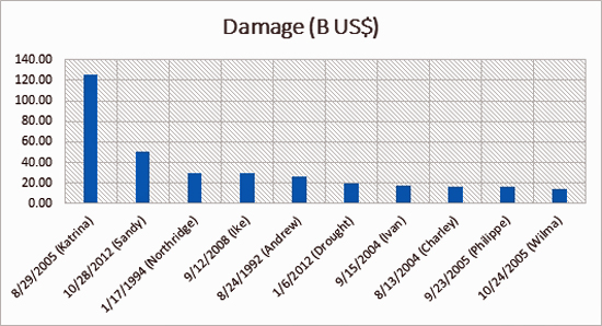
Figure 1: Damages from recent natural disasters in the US. The name of the disaster follows the year of occurrence. Source EM-DAT (2014).
Throughout history, infrastructure resilience has been defined in numerous ways, the most widely used and most objective is by the National Infrastructure Advisory Council (NIAC*) (2009), which states:
"Infrastructure resilience is the ability to reduce the magnitude and/or duration of disruptive events. The effectiveness of a resilient infrastructure or enterprise depends upon its ability to anticipate, absorb, adapt to, and/or rapidly recover from a potentially disruptive event."
No city is immune to challenges, whether natural or manmade, and given the world's growing population, more people than ever are in the potential path of catastrophe. Fortunately, cities can become resilient and withstand shock and stress. As conditions change over time, cities that are resilient can evolve in the face of disaster and stop failure from rippling through systems; they can reestablish function quickly and avoid long-term disruptions.
This resource page explores different aspects of resilience management, to control and help reduce the rapidly increasing costs of manmade and natural hazards and ensure that civil infrastructure exhibits a high degree of resilience. A definition of resilience that incorporates using four components—robustness, resourcefulness, recovery and redundancy—is presented and its manifestation in building systems is covered.
Stakeholders of buildings stand to benefit from resilience management. Businesses locate where they can rely on critical infrastructure. Communities that become resilient will increasingly attract businesses because executives know they can rely on the services and workforce availability, even in the face of disruptive events.
Natural and manmade hazardous events are unpredictable, but they are still inevitable and impose a devastating cost to civil infrastructure. By improving and maintaining the operational and physical performance of our nation's building stock, strategies for resilience can be developed.
When planning and designing buildings, it is appropriate to try to mitigate the potential of the spiraling cost of operational failures by opting for more resilient performance through well-thought-out investments in better planning and designs. It no longer makes sense to wait until after a crisis to implement resilience efforts. Resiliency strategies for buildings should be discussed and implemented now, so there is a greater chance of increased performance, not only today but for the future, benefiting all buildings stakeholders.
Description
Components of Building Resilience
The 4–Rs
The NIAC (2009) determined that resilience can be characterized by four key features:
Robustness: the ability to maintain critical operations and functions in the face of crisis. This includes the building itself, the design of the infrastructure (office buildings, power generation, distribution structures, bridges, dams, levees), or in system redundancy and substitution (transportation, power grid, communications networks).
Resourcefulness: the ability to skillfully prepare for, respond to and manage a crisis or disruption as it unfolds. This includes identifying courses of action and business continuity planning; training; supply chain management; prioritizing actions to control and mitigate damage; and effectively communicating decisions.
Rapid recovery: the ability to return to and/or reconstitute normal operations as quickly and efficiently as possible after a disruption. Components of rapid recovery include carefully drafted contingency plans, competent emergency operations, and the means to get the right people and resources to the right places.
Redundancy, is proposed as another key feature, which mean that there are back-up resources to support the originals in case of failure that should also be considered when planning for resilience.
These four resilience features are simply called the 4Rs. Resilience is multidisciplinary and needs the cooperation of different disciplines for successful outcome. Without multidisciplinary cooperation and contributions, there cannot be successful or efficient resilient infrastructure.
A beneficial illustration of resilience was introduced first by Mary Ellen Hynes (2001) and then by Bruneau et. al (2003). Figure 3 shows graphically how to objectively estimate the resilience of an asset or community by utilizing resilience charts. The illustration shows how an undesirable event might affect two assets (or communities). The operations of asset (or community) "A" will immediately lose some operational quality, then start recovering until returning back to full operational quality. As for asset (or community) "B," it will lose much of its operational quality when subjected to the same undesirable event. It will recover but on a much slower pace than asset "A." Thus, it is concluded that "A" is more resilient than "B." The area under the curve describes the time-operational quality behavior of the asset or community to objectively assess the resilience of the asset or community.
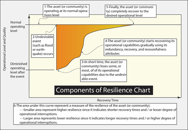
Figure 2: Resilience definition in the time-operational quality space (showing the Resilience Chart).
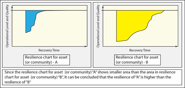
Figure 3: Comparison between the Resilience of two Assets (or communities) using Resilience Charts.
Asset (Building) Resilience and Community Resilience
One of the objectives is to clarify distinctions and relationships between three of the emerging paradigms: risk, resilience, and sustainability. First, risk is expressed as the relationship between a particular hazard (or threat) that might degrade the performance of the infrastructure under consideration and the consequences that might result from a degradation of performance (Gutteling and Wiegman 1996, FEMA 2005, and NRC 2010). Most professional industries, such as engineering, finance, insurance and medicine, adopt a variant of this particular definition of risk (Gutteling and Wiegman 1996). In the building/infrastructure community, FEMA (2005) uses an objective risk definition that states:
Risk rating = function (Consequences, Threat, Vulnerability — C, T, V)
The type of risk function also depends on the desired degree of complexity of risk analysis.
It was established earlier that a reasonable resilience definition relates resilience to robustness, resourcefulness, recovery, and redundancy (the 4Rs). It can be shown that the 4Rs can be recast as a subset of C, T, V. Ettouney and Alampalli, 2012, proposed a relationship similar to that shown in Table 1. These relationships are illustrated in Figure 4.
Table 1 - Relationships Between Risk and Resilience
| Risk Components | Resilience Components | |||
|---|---|---|---|---|
| Robustness | Resourcefulness | Recovery | Redundancy | |
| Consequences | Minor | Major | Major | Major |
| Threat | Major | Minor | Minor | Major |
| Vulnerability | Major | Minor | Minor | Major |
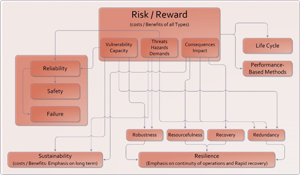
Figure 4: Risk, Resilience, Sustainability Interrelationships
Resilience Management-Based Building Designs
There is an essential distinction between asset resilience and community resilience. As the label implies, asset resilience is the resilience of a single asset. For immediate purposes, an asset is considered to be an individual building. Note that other types of assets are also feasible such as bridges, mass transit stations, transmission towers, or tunnels. DHS (2009) and the American Society of Civil Engineers (ASCE) Report Card (2013), each contain a comprehensive list of types of assets.
Asset resilience is described using the resilience definition above with the 4Rs. Within an asset, different parameters (sometimes referred to as considerations) control asset resilience. These parameters can be categorized as components of one or more of the 4Rs. Table 2 shows a simplified example of building components and categorizations in an asset resilience setting. Note that Columns fit in more than one resilience component (robustness and redundancy). In addition to the categorizations of Table 2, a functional diagram, called a network or a graph, needs to be established. This network shows dependencies of different parameters. The dependencies are expressed by arrows from the controlling parameter to the dependent parameter. If there is no obvious dependence between two linked parameters, then a simple line connecting the two parameters is used. Figure 5 shows a simple network for an asset resilience of a tall building. Capturing important parameters (both operational and physical) as well as their interdependencies as shown in Table 2 and 5 are essential first steps for achieving successful asset resilience management.
Table 2 - Resilience Example of Individual Building as an Asset
| Resilience Components | Building Parameters (Considerations) |
|---|---|
| R1: Robustness |
|
| R2: Resourcefulness |
|
| R3: Recovery |
|
| R4: Redundancy |
|
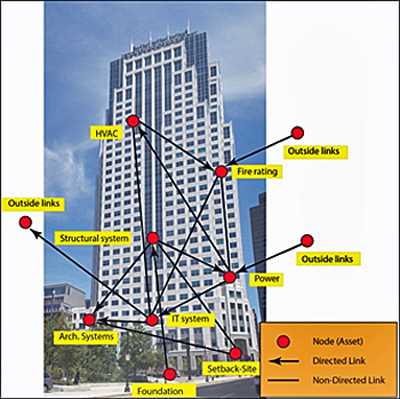
Figure 5: Asset Resilience Links for Resilience Management (Simplified Tall Building Example)
Turning attention to community resilience—as the name implies, a community is comprised of several assets (nodes) that are interconnected via links that may be assets themselves. The nodes and links constitute a community's network. Community resilience is dependent on the resilience of the network's individual asset components (both nodes and links). As an essential step of community resilience management, a greater understanding of the resilience of nodes and links is needed. In addition, community resilience will depend on the topology of the network and how different nodes are linked together.
The size of the community is completely subjective. A community could be a simple campus comprising a small number of buildings (such as a small hospital or college). A community could be a transportation network, a small town, a region, a state, or even a whole country. Each of the 4Rs of community resilience is a function of all of the 4Rs of its nodes and links as well as the topology of the network. Figure 6 shows a simple resilience network for a small community.
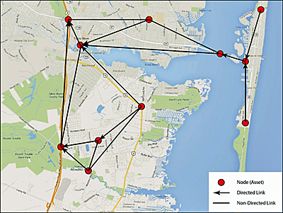
Figure 6: Community Network for Resilience Management
Life Cycle and Cost/Benefit Considerations in Resilience-Based Designs
Incorporating resilience into new building designs, existing building retrofits, and ongoing building operations can carry significant costs. To justify investments in resilience it is imperative to evaluate the cost/benefit relationship of the investments over the full life cycle of the facility. To evaluate increasing resilience, it is necessary to identify performance (or for safety and security objectives, protection) levels and their impact on reducing risk and increasing resilience. With performance/protection levels identified, the costs associated with achieving the performance/protection identified can be calculated and used to evaluate the benefits of higher resilience. The relationships between functional performance, risk, resilience, and cost are identified in Figure 7.
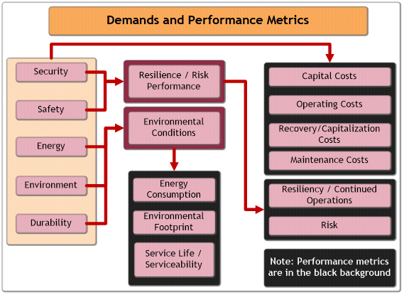
Figure 7: Risk, Resilience, and Performance Relationships
Establishing the tradeoffs between performance and cost requires evaluating the relationships between the cost of providing building systems, their performance over the life of the facility, including response to undesirable events and the interrelationships between systems and performances. Traditional first-cost estimating approaches cannot effectively handle these evaluations. Evaluating Total Cost of Ownership (TCO) is a more effective way to analyze all of the cost factors identified in Figure 7. TCO is calculated by establishing capital cost for the building or improvement and then adding to it the discounted costs of future expenses (operations, maintenance, recovery) to arrive at a TCO. TCO can then be compared for different configurations to perform a cost analysis of the benefits of increasing performance to increase resilience. This methodology is implemented in a DHS project entitled Owners Performance Requirements for Building Envelopes. More information about the approach and access to a tool that implements it is available at www.oprtool.org.
Short-Term Versus Long-Term Resilience Planning
It has been shown that long-term planning can help immensely in cost savings (see FEMA [1996] and MMC [2005]). An objective way to accommodate such long-term cost savings is by following a reasonable resilience management procedure during planning, design, and throughout the life span of the building. Some details of resilience management components are offered in the Resilience Assessment and Resilience Acceptance information below.
Existing Structures Versus New Buildings
The options for enhanced resilience available to existing buildings are more limited than for new building construction. For existing buildings, an appraisal will help determine whether an economical upgrade may be constructed without adversely affecting the existing structure and whether the upgrade is economically feasible. This will help determine whether the risks are worth taking and whether the building is suitable for a proposed function. The structural engineer must evaluate both the risk and the economic feasibility.
If an upgrade is found to be worth pursuing, the engineer must determine the as-built building information, such as the type and arrangement of existing vertical and lateral-force-resisting systems, and the nonstructural components that either affect the structure's stiffness, strength, or the continuity of the structural load path. The as-built information primarily focuses on the load-resisting components, which include structural and nonstructural components that participate in resisting gravity loads, whether or not they were intended to do so by the original designers. This information typically identifies potential discontinuities in the load path, weak links, irregularities, inadequate strength, and stiffness.
The available construction documents may provide primary gravity and lateral-force-resisting elements, critical components, and connections. In the absence of a complete set of building drawings, the design team must perform a thorough investigation of the building. This typically requires the examination of concrete, reinforcing steel, and connector steel samples for physical condition. Generally, mechanical properties for both concrete and reinforcing steel can be established from combined core and specimen sampling at similar locations, followed by laboratory testing. Core drilling should minimize damage of the existing reinforcing steel as much as is practicable. Nominal material properties, or properties specified in construction documents, shall be taken as lower-bound material properties.
Structural steel components constructed after 1900 shall be classified based on ASTM specification and material grade and, if applicable, shape group. Lower-bound material properties may be taken for known steel materials or may be based on tests where the material grade or specified value is not known. The carbon equivalent of the existing components must be determined to establish weldability of the material.
The K factor is typically used to express the confidence with which the properties of the building components are known. The K factor is based on original construction documents or condition assessments, including destructive or nondestructive testing of representative components.
Resilience Assessment
The first component in resilience management is to assess the resilience level of either the asset or the community of interest. Since resilience is a special representation of risk, it is natural to utilize risk assessment methods when trying to assess resilience. Some of the methods for assessing risk are based on subjective processes (Gutteling and Wiegman 1996), while others are based on objective processes (DHS 2011b, 2011c, and 2011d). There are detailed relative and absolute risk assessment methods available (Ettouney and Alampalli 2012a and 2012b). There are even probabilistic or deterministic risk assessment methods (Fenton and Neil 2013).
It is possible to use any or all of these methods for resilience assessment. Since resilience is based on the 4Rs, the parameters of each of the 4Rs in each asset need to be determined, and the desired methodology (which can be borrowed from any desired risk methodology) must be followed. After that, computing an objective or subjective resilience rating can be achieved in a simple and accurate manner. DHS 2011b, 2011c, and 2011d followed these procedures to compute resilience ratings for tunnels, subway stations, and buildings.
Assessing community and network resilience can be achieved using the resilience ratings from different assets and links between those assets in a network setting.
Resilience Acceptance
Setting acceptance thresholds is perhaps the most difficult step in asset (or community) management. Traditionally, a prescribed acceptance threshold was adopted in civil infrastructure projects and based on a reasonable, yet subjective, probabilistic non-exceedance1 value (Ettouney and Alampalli 2015a and 2015b). (Note that an example of probabilistic non-exceedance is stating that there is a 95 percent probability that the next flood in a particular area will not exceed a particular damaging level.) This practice was reasonable enough for its time, since civil infrastructure projects were mostly based on ensuring safety. With the advent of risk-based paradigms, where project decisions are based on safety as well as cost (both life-cycle costs and initial capital expenditures), setting risk acceptance thresholds has become more difficult to define. The same holds true for resilience. Objectively, what is a reasonable acceptance threshold for resilience of a particular asset or particular community? The answer to this question is as important as defining and assessing resilience. For without setting a threshold, resilience improvement projects could be either unnecessarily costly or result in reduced performance (see Figure 8). At the time of this writing, there were few objective methods available for setting reasonable resilience acceptance thresholds but some general suggestions can be made regarding methodologies for setting resilience thresholds. A simple approach is to try to set the acceptance threshold so as to minimize total costs, as illustrated in Figure 8.
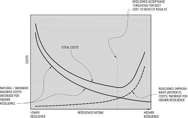
Figure 8: Business Case for Resilience Acceptance
Additional Resources
Publications
- "A Framework to Qualitatively Assess and Enhance the Seismic Resilience of Communities" by Bruneau, M, Chang, S, Eguchi, R., O'Rourke, T., Reinhorn, A., Shinozuka, M., Tierney, K., Wallace, W., Winterfelt, D. Earthquake Spectra Journal Vol. 19, No. 4: 733-752, Earthquake Engineering Research Institute, 2003.
- ASEC Report Card for America's Infrastructure by American Society of Civil Engineers, Reston, VA: ASCE 2013.
- Costs and Benefits of Natural Hazard Mitigation by Federal Emergency Management Agency Report, Washington, DC: FEMA, 1996./li>
- Critical Infrastructure Resilience Final Report and Recommendations by National Infrastructure Advisory Council (NIAC), Washington, DC: NIAC, 2009.
- EM-DAT: The OFDA/CRED International Disaster Database by Université Catholique de Louvain. Brussels, Belgium: EM-DAT, accessed on April 2014.
- Exploring Risk Communications by Gutteling, J. and Wiegman, O. Dordrecht, The Netherlands: Kluwer Academic Publishers, 1996.
- High Performance Based Design for the Building Envelope: A Resilience Application Project Report, Building and Infrastructure Protection Series, Washington, DC: DHS 2011.
- Infrastructure Health in Civil Engineering: Applications and Management by Ettouney and Alampalli. Boca Raton, FL: CRC Press, 2012.
- Infrastructure Health in Civil Engineering: Theory and Components by Ettouney and Alampalli. Boca Raton, FL: CRC Press, 2012.
- Integrated Rapid Visual Screening of Buildings, Building and Infrastructure Protection Series, Washington, DC: DHS, 2011.
- Integrated Rapid Visual Screening of Mass Transit Stations, Building and Infrastructure Protection Series, Washington, DC: DHS, 2011.
- Integrated Rapid Visual Screening of Tunnels, Building and Infrastructure Protection Series, Washington, DC: DHS, 2011.
- Multihazard Considerations in Civil Infrastructure by Ettouney & Alampalli. Boca Raton, FL: CRC Press, 2016.
- National Infrastructure Protection Plan by Department of Homeland Security, Washington, DC: DHS, 2009.
- Natural Hazards Mitigation Saves: An Independent Study to Assess the Future Savings from Mitigation Activities: Volume 1 - Findings, Conclusions, and Recommendations by National Institute of Building Sciences Report, Washington, DC: MMC, 2005.
- Personal Communications by Hynes, Mary Ellen. Vicksburg, MS: 2001.
- Review of the Department of Homeland Security's Approach to Risk Analysis, National Academic Press, Washington, DC: NRC 2010.
- Risk Assessment: A How-To Guide to Mitigate Terrorist Attacks, Risk Management Series, FEMA 452 by Federal Emergency Management Agency, Washington, DC: FEMA, 2005.
- Risk Assessment and Decision Analysis with Bayesian Networks by Fenton, N., and Neil, M. CRC Press, Boca Raton, FL: 2013.
- Risk Management in Civil Infrastructure by Ettouney & Alampalli. CRC Press, Boca Raton, FL: 2016a.
Footnotes
1 [An example of probabilistic non-exceedance is stating that there is a 95% probability that the next flood in a particular area will not exceed particular damaging level.]
Building Resilience: Crime Prevention Through Environmental Design
Introduction
Within This Page
Security design and access control is more than bars on windows, a security guard booth, a camera, or a wall. Crime prevention involves the systematic integration of design, technology, and operation for the protection of three critical assets-people, information, and property. Protection of these assets is a concern and should be considered throughout the design and construction process.
The most efficient, least expensive way to provide security is during the design process. Designers who are called on to address security and crime concerns must be able to determine security requirements, must know security technology, and must understand the architectural implications of security needs.
The process of designing security into architecture is known as "crime prevention through environmental design" (CPTED). It involves designing the built environment to reduce the opportunity for, and fear of, stranger-to-stranger predatory crime. This approach to security design is different from traditional crime prevention practice, which focuses on denying access to a crime target with barrier techniques, such as locks, alarms, fences, and gates. CPTED takes advantage of opportunities for natural access control, surveillance, and territorial reinforcement. It is possible for natural and normal uses of the environment to meet the same security goals as physical and technical protection methods.
CPTED strategies are implemented by:
- Electronic methods: Electronic access and intrusion detection, electronic surveillance, electronic detection, and alarm and electronic monitoring and control
- Architectural methods: Architectural design and layout, site planning and landscaping, signage, and circulation control
- Organizational methods: Manpower, police, security guards, and neighborhood watch programs
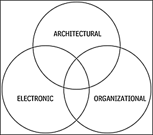
CPTED Strategies All images courtesy of Randall I. Atlas
CPTED Concepts
Concepts involved in crime prevention through environmental design are described below.
Defensible Space
Oscar Newman coined the expression "defensible space" as a term for a range of mechanisms, real and symbolic barriers, strongly defined areas of influence, and improved opportunities for surveillance that combine to bring the environment under the control of its residents.
Natural Access Control
Natural access control involves decreasing opportunities for crime by denying access to crime targets and creating a perception of risk in offenders. It is accomplished by designing streets, sidewalks, entrances, and neighborhood gateways to mark public routes, and by using structural elements to discourage access to private areas.
Natural Surveillance
A design concept intended to make intruders easily observable, natural surveillance is promoted by features that maximize visibility of people, parking areas, and entrances. Examples are doors and windows that look onto streets and parking areas, pedestrian-friendly sidewalks and streets, front porches, and adequate nighttime lighting.
Territorial Reinforcement
Physical design can create or extend a sphere of influence. In this setting, users develop a sense of territorial control, while potential offenders perceive this control and are discouraged from their criminal intentions. Territorial reinforcement is promoted by features that define property lines and distinguish private spaces from public spaces, such as landscape plantings, pavement design, gateway treatments, and fences.
Management and Maintenance
It is important to maintain neighborhoods and residences, and keep security components in good working order. Equipment and materials used in a dwelling should be designed or selected with safety and security in mind.
Legitimate Activity Support
Legitimate activity for a space or dwelling is encouraged through the use of natural surveillance and lighting, and architectural design that clearly defines the purpose of the structure or space. Crime prevention and design strategies can discourage illegal activity and protect a property from chronic problem activity.
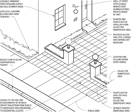
Security layering of spaces
Strategies
Designing CPTED and security features into buildings and neighborhoods can reduce opportunities for, and vulnerability to, criminal behavior and help create a sense of community. The goal is to create safe places through limited access to properties, good surveillance, and a sense of ownership and responsibility.
Natural Access Control and Surveillance
- Use walkways and landscaping to direct visitors to the proper entrance and away from private areas.
- All doorways that open to the outside as well as sidewalks and all areas of the yard should be well lit.
- Make the front door at least partially visible from the street and clearly visible from the driveway or parking lot.
- Windows on all sides of the building should provide full views of the property. The driveway should be visible from the front or back door and from at least one window.
- Properly maintained landscaping should provide good views to and from the building.
Territorial Reinforcement
- Entryways or vestibules create a transitional area between the street and the building.
- Define property lines and private areas with plantings, pavement treatments, or fences.
- The street address should be clearly visible from the street, with numbers a minimum of 5 in. high and made of nonreflective material.
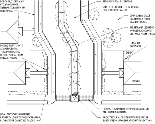
Crime Prevention through Environmental Design - Plan View
Subdivisions and Office Parks
Natural Access Control
- Limit access to the subdivision without completely disconnecting it from neighboring areas. However, try to design streets to discourage cut-through traffic.
- Paving treatments, plantings, and architectural design features such as columned gateways can guide visitors away from private areas.
- Locate walkways where they can direct pedestrian traffic and remain unobscured.
Natural Surveillance
- Landscaping should not create blind spots or hiding places.
- Locate open green spaces and recreational areas so they can be observed from nearby houses.
- Use pedestrian-scale street lighting in areas with high pedestrian traffic.
Territorial Reinforcement
- Design lots, streets, and houses to encourage interaction between neighbors.
- Accent entrances with changes in street elevation, different paving materials, and other design features.
- Clearly identify residences with street address numbers that are a minimum of 5 in. high and are well lit at night.
- Property lines should be defined with post-and-pillar fencing, gates, and plantings to direct pedestrian traffic.
- All parking should be assigned.
Multi-Family Dwellings
Natural Access Control
- Balcony railings should never be made of a solid, opaque material or be more than 42 in. high.
- Define parking lot entrances with curbs, landscaping, and/or architectural design; block dead-end areas with a fence or gate.
- Common building entrances should have locks that automatically lock when the door closes.
- Limit access to the building to no more than two points.
Natural Surveillance
Territorial Reinforcement
- Define property lines with landscaping or post-and-pillar fencing, but keep shrubbery and fences low to allow visibility from the street.
- Accent building entrances with architectural elements and lighting and/or landscape features.
- Doorknobs should be 40 in. from window panes.
- Clearly identify all buildings and residential units with well-lit address numbers a minimum of 5 in. high.
- Common doorways should have windows and be key-controlled by residents.
- Locate mailboxes next to the appropriate residences.
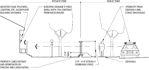
Crime Prevention Through Environmental Design - Sectional View
Additional Resources
Publications
- "A Framework to Qualitatively Assess and Enhance the Seismic Resilience of Communities" by Bruneau, M, Chang, S, Eguchi, R., O'Rourke, T., Reinhorn, A., Shinozuka, M., Tierney, K., Wallace, W., Winterfelt, D. Earthquake Spectra Journal Vol. 19, No. 4: 733-752, Earthquake Engineering Research Institute, 2003.
- ASEC Report Card for America's Infrastructure by American Society of Civil Engineers, Reston, VA: ASCE 2013.
- Costs and Benefits of Natural Hazard Mitigation by Federal Emergency Management Agency Report, Washington, DC: FEMA, 1996./li>
- Critical Infrastructure Resilience Final Report and Recommendations by National Infrastructure Advisory Council (NIAC), Washington, DC: NIAC, 2009.
- EM-DAT: The OFDA/CRED International Disaster Database by Université Catholique de Louvain. Brussels, Belgium: EM-DAT, accessed on April 2014.
- Exploring Risk Communications by Gutteling, J. and Wiegman, O. Dordrecht, The Netherlands: Kluwer Academic Publishers, 1996.
- High Performance Based Design for the Building Envelope: A Resilience Application Project Report, Building and Infrastructure Protection Series, Washington, DC: DHS 2011.
- Infrastructure Health in Civil Engineering: Applications and Management by Ettouney and Alampalli. Boca Raton, FL: CRC Press, 2012.
- Infrastructure Health in Civil Engineering: Theory and Components by Ettouney and Alampalli. Boca Raton, FL: CRC Press, 2012.
- Integrated Rapid Visual Screening of Buildings, Building and Infrastructure Protection Series, Washington, DC: DHS, 2011.
- Integrated Rapid Visual Screening of Mass Transit Stations, Building and Infrastructure Protection Series, Washington, DC: DHS, 2011.
- Integrated Rapid Visual Screening of Tunnels, Building and Infrastructure Protection Series, Washington, DC: DHS, 2011.
- Multihazard Considerations in Civil Infrastructure by Ettouney & Alampalli. Boca Raton, FL: CRC Press, 2016.
- National Infrastructure Protection Plan by Department of Homeland Security, Washington, DC: DHS, 2009.
- Natural Hazards Mitigation Saves: An Independent Study to Assess the Future Savings from Mitigation Activities: Volume 1 - Findings, Conclusions, and Recommendations by National Institute of Building Sciences Report, Washington, DC: MMC, 2005.
- Personal Communications by Hynes, Mary Ellen. Vicksburg, MS: 2001.
- Review of the Department of Homeland Security's Approach to Risk Analysis, National Academic Press, Washington, DC: NRC 2010.
- Risk Assessment: A How-To Guide to Mitigate Terrorist Attacks, Risk Management Series, FEMA 452 by Federal Emergency Management Agency, Washington, DC: FEMA, 2005.
- Risk Assessment and Decision Analysis with Bayesian Networks by Fenton, N., and Neil, M. CRC Press, Boca Raton, FL: 2013.
- Risk Management in Civil Infrastructure by Ettouney & Alampalli. CRC Press, Boca Raton, FL: 2016a.
Building Science Concepts
Introduction
Within This Page
This resource page is the first of a series on relevant topics in building science. It is aimed at explaining the key concepts involved in building science, as well as the relationship of this discipline to the architecture / engineering / construction (AEC) industry. It focuses on the systems approach to building technology and the utility of building science to advance the high-performance building agenda.
It should be recognized that prior to the introduction of the systems approach to the discipline of building science, most of research and practice dealt with construction materials and components. The consideration of the entire building system, or in some instances sub-systems, did not emerge until the limits of a less holistic approach became painfully obvious in the form of building defects and failures.
A great deal of research and development toward the advancement of the systems approach remains to be accomplished. Despite their limitations, the system models that have been adopted by modern building science have delivered an overwhelming improvement in the health, safety, and durability of buildings. For this reason, more than any other, building science is now recognized in most developed countries as the core of technical training for architects, explaining why buildings work, why buildings fail, and how to avoid the latter without compromising the artistic, cultural, and environmental qualities of the architectural artifact.
Description
Building Science Defined
Building science is a field of knowledge that draws upon physics, chemistry, engineering, architecture, and the life sciences. Understanding the physical behavior of the building as a system and how this impacts energy efficiency, durability, comfort and indoor air quality is essential to innovating high-performance buildings. Modern building science attempts to work with models of the building as a system, and to apply empirical techniques to the effective solution of design problems.
Neil Hutcheon, the famous Canadian building scientist, defined building science as "a term now widely used, for want of a better one, to describe the growing body of knowledge about the relevant physical science and its application."i
More specifically, contemporary building science is a broad discipline that is concerned with the full life cycle of buildings, including:
- policy (codes and standards);
- planning;
- design;
- construction;
- commissioning;
- facilities management;
- forensics and rehabilitation;
- restoration and retrofit;
- preservation and conservation; and
- demolition (deconstruction) and recycling.
The disciplinary involvement in contemporary building science ranges from the physical and engineering sciences, to economics, political science, behavioral sciences, life sciences, and architecture.ii
The importance of contemporary building science is often fully appreciated after the occurrence of building performance problems, or worse, after failures, rather than at the planning and design stage of building projects. For this reason, contemporary building science has taken on greater importance in response to an increasing trend of innovative departures from traditional building practices based on successful past precedents.
Innovation is not a trial and error process that relies on gradually refining past precedents. It is usually a significant departure from normative practices and relies on the scientific method to advance its agenda. Modern building science, as it is known today, was born of innovation - more correctly, because of the large number of failures encountered when building designers attempted to innovate without applying building science principles. There was no need for building science when only successful precedents were copied and handed down from one generation to the next, but there was also no advancement toward high-performance buildings within traditional building practices.
Building System Theory
Modern systems theory is an expansive body of knowledge with many branches. It is not possible to deal with the full range of theories within these resource pages, but consider these concepts of a system.iii
A system is an integrated assembly of interacting elements, designed to carry out cooperatively a predetermined function. [Gibson 1960]
A system is an integrated network of interacting elements, receiving certain inputs and producing certain outputs, given certain constraints. [Chappelle 1966]
Systems theory, at its fundamental level, is a belief that the world is made up of set(s) of interacting components, and that those sets of interacting components have properties, when viewed as a whole, that do not exist within any of the smaller units. [Allen 1996]
A systems approach is essentially:
- A way of organizing observations;
- A way of thinking about related objects and processes;
- A way of talking about (labeling) the parts (components) of a system; and
- An outcome from systematically considering systemic phenomena.
Systems thinking is an important part of building science because it helps simplify problems by classifying them according to common types. There exist millions of buildings and their diversity would be overwhelming were it not for the systems approach. This approach is derived from general systems theory and the basic characteristics common to all systems are important to keep in mind when applying building science.
Boundaries and Boundary Criteria—Many people believe that a building system ends at the outer surface of its enclosure, in some cases at the property line. But in reality, the building system extends to the outer reaches of what it impacts, and what impacts the building. Basement flooding due to municipal sewer surcharge is an example of the building's plumbing system extending to the local municipal infrastructure services.
Flows and Storage—Inhabitants, energy, water, sewage, and data are examples of the flows and storage characteristics of the building as a system. Occupant behavior is among the most difficult flows to accurately predict in energy models.
Transformations—Buildings age and they are modified by their users, not always in a beneficial way. It is desirable from a life cycle perspective to design buildings that can adapt and adopt new technologies to improve their performance and minimize functional obsolescence.
Spatial and Temporal Hierarchies—Passive survivability and safe/secure building design are premised on achieving spatial and temporal resilience such that the vital functions are maintained both in day-to-day operations and under extreme conditions such as natural and man-made disasters.
Feedback and Control Loops—Buildings are prosthetic extensions of the human body and as such rely on many forms of cybernetics to control the indoor environment and maintain safety and security.
Each of the above characteristics vary in importance, depending on the type of building being designed and its intended use. Building science specialization is often needed to deal with particular aspects of these characteristics (e.g., energy modeling, flood proofing, durability, indoor air quality, blast resistance, etc.). But in all cases, the fundamental understanding of how these characteristics interact may be derived from the building as a system model.
The Building as a System
The idea of the building as a system springs from modern systems theory and the application of building science principles to building behavior and performance.
The building as a system concept is a relatively new development in building science. It resulted directly from the introduction of a systems approach, to building science practice, starting in the 1960s. As innovation increasingly became the means to achieving new forms of architectural expression in the 20th century, analysis and review of building failures indicated that traditional approaches to design were inadequate. This was due to inappropriate adaptations of successful past precedents, or an unknowingly narrow analysis at the building component level for radical departures from technical norms. In both cases the behavior of the whole system was not considered.
The building as a system approach, as depicted in Figure 1, requires designers to explicitly and consciously consider the interactions between the primary elements comprising the system:
- Building enclosure (building envelope system);
- Inhabitants (humans, animals, and/or plants, etc.);
- Building services (electrical/mechanical systems);
- Site, with its landscape and services infrastructure; and
- External environment (weather and micro-climate).
Harmonization of these elements is the key to well-performing buildings.
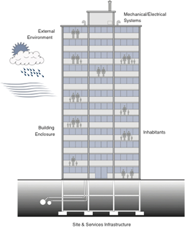
Figure 1. The building as a system model.
Returning to the highly specialized nature of contemporary building science, it is recognized that a large number of materials, components, equipment, and assemblies must be properly integrated to achieve a high-performance building. At the same time, it must be appreciated that most performance problems involve the building enclosure, which also represents the primary passive environmental control system. In view of these considerations, this Resource Page is largely focused on the building science underlying building enclosures and how they are influenced by climate and weather. A comprehensive listing of design parameters may be found in the Resource Page on Building Enclosure Design Principles and Strategies.
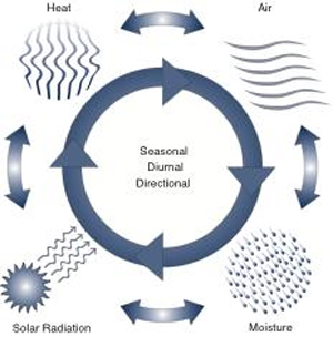
Figure 2. Physical mechanisms driving the behavior of the building as a system.
Recognizing that the physical forces affecting structural integrity must always be adequately resolved, there remain four primary physical mechanisms associated with climate and weather that drive the behavior of the building as a system in terms of its role as a moderator of the indoor environment (see Figure 2):
Heat Flow - the conductive, convective, and radiative flow of heat;
Air Flow - the air flow across and within the building enclosure due to air leakage and ventilation;
Moisture Flow - the flow of water and vapor across and within the building enclosure; and
Solar Radiation - the influence of insulation on the opaque and transparent enclosure components.
In the building as a system, all of these physical mechanisms are occurring in various combinations at various times. During cold periods, heat and warm moist air escape through leaks in the building enclosure. To compensate, the heating system must supply the amount of heat being lost, and to replace the lost moisture, the indoor air must be humidified for occupant health and comfort. During hot periods, heat and warm moist air are driven into the building and the HVAC system must cool and dehumidify. Under all conditions, the building enclosure must manage the heat, air, and moisture flows. The occupants can exert as great an influence as the climate through their activities. This explains why a building may be very fit for one occupancy (e.g., warehouse or factory), but then experience problems when the occupancy changes (e.g., residential or institutional). Problems occur when the balance of moisture, heat, and air flows is disturbed beyond the performance thresholds of the building as a system.
The key to the fitness of a building is the balanced control of these physical mechanisms, so that durability, comfort, energy efficiency, indoor air quality, health, and safety are not compromised.
Building Performance
The term "performance" may be defined as the level of service provided by a building material, component, or system, in relation to an intended, or expected, threshold or quality.
For example, the structural performance of a building may be judged in terms of its resistance to dead, live, soil, wind, hydrostatic, and seismic loads as prescribed by applicable codes. Within the established thresholds for these loads, the structure would be required to behave adequately according to expectations in terms of strength, durability, deflections, and vibrations.
When the intended or expected level of performance is not achieved, the resultant behavior is termed a "failure" which must not be confused with the term "defect", a minor damage or blemish which has no immediate or significant impact on performance, and which may be suitably repaired.
An important contribution of building science is the quantification of performance parameters such that many of these can be predicted at the design stage, and assessed / confirmed after the building is occupied and operational. This preoccupation with prediction and validation has led to the appreciation of the need for a systems approach, as building scientists grapple with issues such as indoor air quality and sustainable buildings.
The significant thing to remember about inadequate building performance is that it results in the vast majority of litigation, and the application of building science via the systems approach is among the more effective preventive measures against failures and defects. It is also a highly useful diagnostic tool when assessing the condition of existing buildings that are candidates for restoration and retrofit. In order to deploy the systems approach in the design and assessment of buildings, it is first necessary to establish a framework of performance requirements. The section which follows deals with the ongoing development of such a framework based on the pioneering work of the late Neil Hutcheon, former Director of the Division of Building Research at the National Research Council Canada.iv Figure 3 depicts a hierarchy of performance requirements derived from building science principles.v
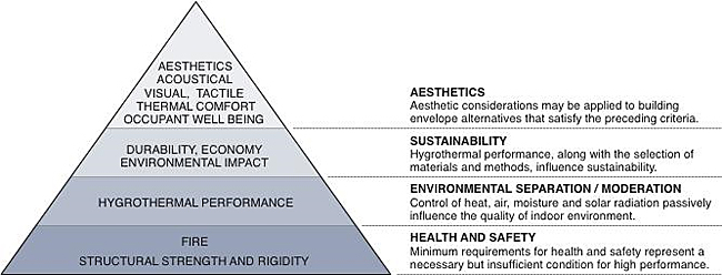
Figure 3. Building science hierarchy of performance requirements.
To borrow from mathematical terminology, building science is a necessary but insufficient condition for great architecture. However, its pivotal supporting role cannot be underestimated in importance. The vast majority of litigation between parties to construction projects involves the inadequate performance of building elements that are intended to provide firmness and commodity. Inferior delight is still only punishable by the rebukes of peers and critics, and has so far eluded the grasp of litigation and legislation.
The concept of a building performance framework is intended to explicitly represent:
- External and internal conditions affecting a building system (e.g., climate, weather, site, soils, occupancy, and indoor climate class);
- Parts and inter-relationships comprising a building system (e.g., the behavior of materials, components, equipment and sub-systems);
- Parameters or indicators defining acceptable performance (e.g., aesthetics, health and safety, economy, sustainability, etc.); and
- Methods, tools, and techniques for designing and analyzing performance according to the parameters, inter-relationships and conditions cited above.
Context for Contemporary Building Performance Objectives
Appropriate building performance objectives involve numerous interfaces between the building, its occupants, and the natural and built environment as depicted in Figure 4. Some of these interfaces cannot be regulated (e.g., climate, weather, human physiology, etc.), while others may be manipulated within some prescribed range (e.g., energy efficiency, affordability, etc.). The terms of reference for the regulated aspects of buildings remain in a constant state of flux, as evidenced by the many changes associated with each development cycle of building codes and standards. And the context for building performance in relation to the environment, the economy, and occupant expectations has also changed appreciably in developed countries.
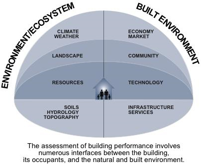
Figure 4. Contemporary context for building performance objectives.
The most significant change in recent times has been the awareness of the ecological impacts of buildings. Today, society recognizes that the building as a system does not arbitrarily end at the property line, and may have far reaching environmental implications. It is reasonable to expect there will continue to be a variety of interpretations of the relative importance (priority) of the factors involved in the performance of building systems.
Rather than dwell on the global scale of building performance concepts and parameters, this discussion will focus on physical aspects of performance that may be objectively quantified and compared.
Relationship between Physics, Materials, Components, and Systems
Performance concepts in building codes and standards have existed largely as constraints guiding the prescriptive codes and standards development process. One of the major challenges in developing an effective building performance objectives framework has been the establishment of explicit parameters supported by building science knowledge, and specialized knowledge from allied disciplines. These are premised on the relationship between physical phenomena and building system behavior.
A building is a system which consists of materials, components (assemblies, equipment), sub-systems, and systems that interact with physical phenomena in the process of providing an intended level of performance to its immediate occupants and societal stakeholders. Focusing on physical phenomena from a building science perspective, the relationship of the constituent elements of a building system and these physical phenomena is depicted in Figure 5.
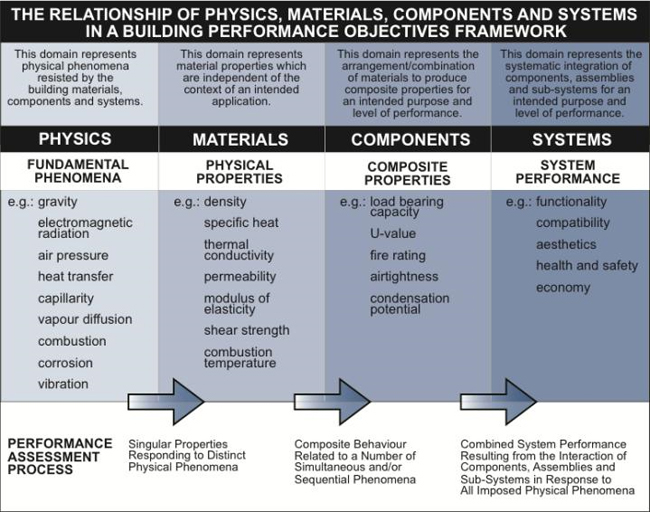
Figure 5. Physics, materials, components, and systems.
The key points to appreciate from this relationship are as follows:
The fundamental physical phenomena imposed on a material, component, or system drive its response (behavior).
The suitability of a material, component, or system must, as a minimum, adequately address the imposed physical phenomena.
The complexity of problems increases dramatically as the design process proceeds from selecting materials, to arranging components, to integrating systems.
The relationship can also be used in reverse, figuratively speaking, to assess the suitability of an existing building system to another set of physical conditions which differ from those originally considered in its design.
Due to the multi-functional nature of components and sub-systems (e.g., a wall may provide structural support, fire safety, and moderation of the environment), it is important to relate constituent elements of the building to a coherent hierarchy of objectives. The hierarchy of physics, materials, components, and systems is a practical means of dealing with performance objectives at the conceptual level, recognizing that it may bear little, if any, resemblance to the actual intellectual process (design). The importance of differentiating between representations of relationships, and the actual reasoning processes which make use of these representations, cannot be underestimated. Research in the fields of artificial intelligence and expert systems has demonstrated that the linkages between knowledge representation and its application require sophisticated interpretation.vi Presumably, the cultivation of sophisticated interpretive skills remains one of the more critical roles for the higher education of design professionals.
A Conceptual Model of Building Behavior
Building behavior (performance) is a highly complex, resultant phenomenon. It involves numerous simultaneous and sequential physical phenomena, and the response of the building as a system will vary depending on the nature and arrangement of the constituent elements. At present, a comprehensive, explicit model of building system behavior has not been developed, but is assumed to exist in some implicit form among the collective of building industry experts. A helpful reminder of the challenge associated with developing a comprehensive system model was provided by Hutcheon (Hutcheon and Handegord, 1983, pp.3-4):
"The design of buildings has been, and still is, to a large extent, based on building practice. Changes have been slow and, in the main, have come about through an evolutionary process of trial and error. Building practice has been fundamentally an inheritance from the past, modified by factors such as climate, economy, social habits, local aesthetic values, and local resources of materials and skills. The evolutionary process works slowly under the influence of new factors; it is equally slow in rejecting the obsolete.
The growth of scientific knowledge has led to great advances in the analysis and rational design of the purely structural functions of a building. There has also been a great deal of development in individual materials and components. As yet, there have been relatively small advances in dealing adequately with all of the combinations of elements and with the complex interrelationships of phenomena involved in the performance of an entire building. The reasons are not hard to find. It is sufficient to note that, even now, contemporary building science draws on the knowledge and experience of almost every branch of engineering science.
We have long since passed the point where we are content to rely on the "trial-by-use" method of assessing changes in design, materials and construction. Many new and interesting materials, systems and methods of design and construction are offered each year. Those responsible for assessing and screening such new developments realize only too well the relative inadequacy of our present knowledge of the suitability of any given material or method. In addition, our standards of performance are continually being raised. As we reduce our major difficulties in turn, minor ones assume greater relative proportions, and we clamour for their reduction or elimination also, in the name of progress. The increasing state of knowledge appears less and less adequate as the demands upon it increase."
Since the time of Hutcheon's observation, a stronger need for a whole system model of building performance has been recognized within the building science discipline. While a broadly accepted model continues to elude building science researchers and practitioners, some advances have been made in various aspects of performance, such as wetting/drying potential of enclosures, window performance, etc. At the conceptual level, approaches such as the general limit states design model have been applied to structural design, however, this approach is not well suited to many areas of building performance (e.g., access and egress, room dimensions, etc.) and the gathering of data may not always be possible even where the model is applicable (e.g., statistics for water leakage in basements).
Given this situation, an attempt to construct a general, extensible schema of building behavior applicable to the whole system, as well as its constituent elements, is presented in Figure 6. At this point, a comprehensive application of the schema to whole building system performance remains to be completed.
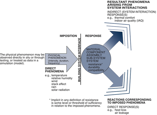
Figure 6. Schema describing physical building behavior.
Based on the schema depicted in Figure 6, it may be noted that by linking a number of simple schemata, complex behavior may be described, if not quantitatively modeled. In the example phenomena depicted in Figure 6, the direct response of the building enclosure to the temperature, air pressure, and humidity difference between the indoor and outdoor environments results in heat loss and air leakage. The indirect response influences thermal comfort and indoor air quality if the enclosure provides low effective thermal resistance (excessive thermal bridging and/or insufficient insulation) and the condensation of moisture promotes mold growth. This approach is useful in constructing more sophisticated models of whole system behavior to aid designers with fundamental performance considerations and system interactions.
At this point in the development of contemporary building science, computational methods for the design and assessment of building systems have not emerged. It has been argued that the integrative process of design will remain an exclusively human task, and that conceptual models in the form of computational technologies will only serve as learning aids and practice guidelines. Regardless of the future of building science, a great deal of progress has been made toward developing simple models of building behavior and arranging them within a framework of performance objectives. The next section presents one such approach to the comprehensive assessment of the physical performance of building systems
A Building Performance Objectives Framework
The framework depicted in Figure 7 is an extension of earlier work pursued by the author.vii It is based on the premise that in the assessment or design process, the key consideration appears to be the performance objective or intent. This view has since been strongly reinforced as many nations move towards objective-based building codes.viii
An interesting aspect of any objective-based framework is that the intent remains constant while the means of achieving the intent or objective continue to evolve with advances in technology. It appears humans will always expect buildings to provide firmness, commodity, and delight, and that architects will always have to find appropriate means of responding to their clients' demands.
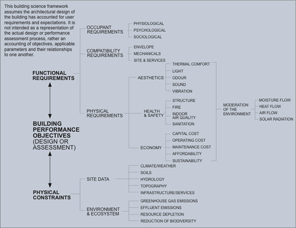
Figure 7. Building performance objectives framework from a building science perspective.
The framework presented in Figure 7 consists of two primary elements:
- The physical constraints which are imposed by site conditions and the limits or thresholds of the global environment and local ecosystem; and
- The functional requirements of buildings that encompass occupant requirements, compatibility requirements, and physical requirements.
Contemporary building science supports the societal objective of sustainable architecture by balancing the physical constraints and the functional requirements, ideally without compromising architectural aesthetics and high performance.
The predominant area of interest for building science is under functional requirements, and within this area further and more specific objectives are identified that constitute the basis for designing and/or assessing physical building system performance.
This, or any performance objectives framework, is intended to provide designers with an explicit means of accounting for compliance with the functional requirements of buildings. While it is possible that future developments in computer technology may automate many aspects of design and assessment,ix it is doubtful that designers will assign significant responsibility to prosthetic applications for assuring due diligence, simply because software cannot shoulder liability.
Finally, if nothing else, this framework exposes the breadth of building science and reinforces the realization that its mastery will require a lengthy commitment to study and practice.
Building System Integration
A common purpose of building science is to achieve building system integration, not by-trial-and-error over many generations of building precedents, but each and every time a building is being designed and built. This implies defining a level of performance and a means of assuring compliance.
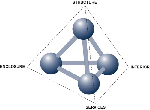
Figure 8. Building system integration involves the building structure, its enclosure (envelope), the interior elements, and the building services (i.e., mechanical, electrical, etc.).
Optimizing performance goes beyond compatibility between the structure, enclosure, interior, and services. It involves the assessment of economic, social, and environmental parameters so that performance targets are attained affordably within the skill capacity of the industry. This effectively means innovation may be defined as achieving better performance and higher quality at less cost over the life cycle of a building or facility.
Applied building science research has indicated the control of moisture in building enclosure design generally takes precedence over other control measures simply because so many of the requirements for the control of heat transfer, air leakage and solar radiation are satisfied when all forms of moisture have been carefully considered. At the time of developing this Resource Page, energy efficiency is a primary goal of most developed nations, and this objective is not compromised by designing building enclosures to manage moisture. The levels of thermal insulation needed to avoid interstitial condensation leading to durability problems are equal to, or higher, than those required to provide cost effective levels of energy efficiency over the life cycle of a building. This is the rationale behind a subsequent set of building science Resource Pages beginning with moisture management in building enclosures.
A number of related Resource Pages are also dedicated to explaining how various performance objectives identified herein may be achieved, but for the purposes of understanding building science concepts, it is important to appreciate that the building enclosure, or envelope, is the primary environmental separator/moderator. It performs a passive role, unlike mechanical and electrical systems, that actively supplement the amount of heat, air, moisture, and daylight the enclosure is unable to provide. When all active systems fail, the building enclosure is the last line of defense between the indoors and the outdoors. High-performance building enclosures provide passive sustainability during extreme weather phenomena and natural disasters, and safely shelter their inhabitants.
Synopsis
In summary of the ideas and relationships that have been presented, the following conclusions may be considered:
Buildings are systems that must be appropriately integrated by designers to achieve defined levels of performance.
Building science provides a disciplined means of dealing with the physical requirements of buildings that is completely compatible with the architectural design and building construction processes.
Innovation in modern architecture relies on building science and the systems approach to ensure that building performance meets the expectations of building owners, inhabitants, and society.
The context for building performance has more recently evolved to include issues of ecology and sustainable development. This expansion of performance parameters, coupled with increasing consumer expectations, has dramatically increased the complexity of buildings. Performance objectives frameworks and conceptual models have become necessary methodologies to assure all aspects of the integration of well performing building systems have been carefully addressed.
For further study on this topic read the concluding chapter to Robert Mark's compendium on Architectural Technology Up to the Scientific Revolution wherein he observes:
"By focusing on a wide range of historic buildings, from their below-ground-level foundations to the peak of their timber roofs, the typical developmental pattern of pre-scientific technology becomes evident. Much of what was then learned through experience and observation is available to today's designers from scientific analysis."x
Contemporary building science has evolved beyond simple analysis and now offers a range of sophisticated design tools, testing protocols, and performance simulation/validation techniques. These have become invaluable supplements to professional experience and the critical observation of actual building performance. The role of contemporary building science within architecture and engineering continues to reinforce the dynamic relationship between theory and practice in the AEC industry.
Additional Resources
Publications
- Building Science for a Cold Climate by Neil Hutcheon and Gus Handegord. Institute for Research in Construction, 1983.
- The Building Systems Integration Handbook, edited by Richard D. Rush. The American Institute of Architects, 1986.
- Building Science for Building Enclosures by John Straube and Eric Burnett. Building Science Press, December 2005.
- Integrated Buildings: The Systems Basis of Architecture by Leonard R. Bachman. John Wiley and Sons, 2003.
Online Sources of Building Science Information
Building science information can be found among a number of sources, such as conference proceedings, journals, studies, and various technical publications made available through government, industry and academia. The sources cited herein represent organizations or institutions that are predominantly involved with building science. For example, sources such as the American Society of Civil Engineers will have a part of their publications dedicated to building science, but for the most part, focus on traditional civil engineering topics. These kinds of organizations have not been listed, but may contain highly relevant building science information.
- Building Science Centre of Excellence Research Database
- Building Science Corporation
- Canada Mortgage and Housing Corporation—Accessible and Adaptable Homes
- Lawrence Berkeley Laboratory—Building Energy Efficiency
- National Institute of Building Sciences
- National Institute of Standards and Technology—Buildings and Construction
- National Renewable Energy Laboratory—Buildings Research
- Natural Resources Canada—Energy Efficiency for Buildings
- Oak Ridge National Laboratory—Building Technologies Program
In addition to the sources cited above, keyword searches on the Internet will yield a number of references for a particular topic. Product manufacturer organizations and government departments dedicated to buildings, or aspects of buildings such as energy efficiency, are also potential sources of invaluable building science information. In order to obtain maximum benefit from these myriad sources of building science information, it is important to gain a foundation of fundamental building science concepts and terminology.
References
i. Building Science for a Cold Climate, NRCC 39017 by Hutcheon, N. B. and Gus Handegord. Ottawa: 1983.
ii. Fields of Research in Building Science (brochure) by Education Liaison Committee. Washington, DC: Building Research Institute, 1963.
iii. 3 Definitions as found in: Hierarchy theory: a vision, vocabulary, and epistemology by Timothy F. H. Allen with Valerie Ahl, illustrated by Paula Lerner. New York: Columbia University Press, 1996.
iv. Fundamental Considerations in the Design of Exterior Walls for Buildings, Technical Report No. 13, Division of Building Research by Hutcheon, N. B. Ottawa: National Research Council Canada, 1953.
v. Development of a Wall Performance Classification System by Kesik, T. and David De Rose. Toronto ON: CIB World Building Congress 2004, May 2–7, 2004.
vi. Knowledge in the Form of Patterns and Neural Network Computing Knowledge Engineering, Volume I, Fundamentals by Pao, Y.H., H. Adeli (editor). New York: McGraw Hill, 1990.
vii. A Knowledge Based Systems Approach to the Assessment of Building Performance Proceedings of the Second Canadian Conference on Computing in Civil Engineering, pp. 469-480 by Kesik, T. and K.A. Selby. Ottawa, Ontario: 1992.
viii. Objective Based Codes: A New Approach for Canada by Canadian Commission on Building and Fire Codes. Ottawa: February 1996.
ix. Towards Integration of Service Life and Asset Management Tools for Building Envelope Systems Proceedings of the Seventh Conference on Building Science and Technology, pp. 153-163 by Lacasse, M.A., D.J. Vanier, B.R. Kyle. Toronto: 1997.
x. Architectural Technology Up to the Scientific Revolution by Mark, Robert (editor). Cambridge, Massachusetts: MIT Press, 1993.
Building Sciences Career Center
Introduction
Little has more impact on our lives than the built environment around us. That built environment exists because of the professionals and skilled tradespeople from multiple disciplines that plan, design, construct, operate, and manage it. They focus on meeting important needs of citizens including providing sustainable, cost effective and safe environments for living, working, playing and learning.
Today's buildings-related professionals and tradespeople make use of cutting edge technology including building information modeling (BIM), computerized maintenance management systems (CMMS), smart controls and renewable energy systems such as solar photovoltaics and wind to deliver high-performance buildings.
For those students interested in pursuing building operations related careers, the Department of Energy, General Services Administration, National Institute of Building Sciences, the Consortium for Building Energy Innovation, Penn State University and Facility Engineering Associates have developed a career map for Building Operations Professional, Energy Auditor, Building Commissioning Professional, and Energy Managers. The Facilities Career Map demonstrates what possible careers look like in terms of sequential positions, roles, credentials, experience and education/training.
The information contained here is intended to provide an introduction to the various disciplines and opportunities within the buildings industry. You are encouraged to explore the rest of the Whole Building Design Guide and contact the organizations identified below for additional insight into career opportunities.
This career center supports the Mars City Facility Ops Challenge developed by the National Institute of Building Sciences, Total Learning Research Institute and National Aeronautics and Space Administration but provides tools for anyone considering a career in the buildings-related disciplines.
Building Science Disciplines
Architecture
- John Jackson, Architect, HOK
- American Institute of Architects (AIA) Career Stages
Architectural Programming
Building Scientist
- Paul Totten, Building Scientist, WSP Group
- Building Science Concepts
Code Official
- Peter Mensinger, Code Official, City of Alexandria, VA
- International Code Council (ICC) High School Technical Training Program
Commissioning Authority
Cost Estimating
Electrical Engineering
Fire Protection Engineering
HVAC and Refrigerating Engineering
- Dunstan Macauley, Mechanical Engineer, WSP Group
- ASHRAE K-12 Activities
- HVACR Workforce Development Foundation: Careers In HVAC
- Why Become an HVAC Technician
- Why Choose a Career in HVACR
Information Technologies Engineering
Interior Design
- Deborah Davis, Interior Designer, Deborah Davis Design
- American Society of Interior Designers (ASID) Student Resources
Landscape Architecture
- Radhika Mohan, Landscape Architect and Urban Planner, City of Alexandria, VA
- American Society of Landscape Architects, Become a Landscape Architect
- Landscape Architecture and the Site Security Design Process
Lighting Design
- David Ghatan, Lighting Designer, CM Kling + Associates
Planning
Plumbing Engineering
Researcher
- Lisa Choe, Building Science Researcher, National Institute of Standards and Technology (NIST)
- Harrison Skye, Building Science Researcher, National Institute of Standards and Technology (NIST)
- Guide to NIST's STEM Education Activities
Structural Engineering
- Robert Victor, Structural Engineer, HDR
- American Society of Civil Engineers (ASCE) Pre-College Outreach
Sustainability Specialist
- Fulya Kocak, Sustainability Director, Clark Construction
- U.S. Green Building Council (USGBC) Center for Green Schools
Welding / Welding Engineering
Woodworker
- Tony Daggett, Cabinet Maker, Architect of the Capitol
Major Resources
Industry STEM/STEAM Education Initiatives
References
Building Systems Efficiency
Introduction
Within This Page
Much progress has been made on improving building energy efficiency over the past decades by focusing on the efficiency of individual building components (i.e., appliances and equipment) and, more recently, the efficiency of the building as a whole. As a middle ground between component and whole-building efficiency, a building systems approach considers the interactions of components within and among building systems, as well as interactions among multiple buildings, and between the building and the electric grid. Adopting a systems perspective will become increasingly necessary to achieve meaningful and cost-effective future energy savings within the built environment.
In addition to improving energy performance, a systems approach has the potential to achieve significant non-energy benefits: reduced carbon emissions (commercial buildings alone account for about 18 percent of direct and indirect greenhouse gas emissions), improved grid reliability , water savings , and extended equipment life and increased occupant comfort and productivity . The quantifiable non-energy benefits have been estimated to range from 25 to 50 percent of the total benefits of energy efficiency across all sectors.
Description
Defining Systems Efficiency and its Role in Whole Building Design and Operation
A building system is a combination of equipment, operations, controls, accessories, and means of interconnection that use energy to perform a specific function. Examples include HVAC, water heating, lighting, thermal envelope, and miscellaneous electrical load systems.
- System energy efficiency is defined as the ratio of the services or functions provided by a building system to the amount of energy that system consumes, taking into account the thermal load imposed on (or thermal energy contributed to) other building systems.
- " To achieve a systems-efficient building, multiple systems (e.g., lighting, HVAC&R) must be designed, installed, and operated to optimize performance collectively with other energy systems both within and outside of the building to provide a high level of service for a given level of energy use.
Whole Building Design includes both an integrated design approach and an integrated team process. An integrated design approach ensures that the interrelationships and interdependencies with all building systems are understood, evaluated, appropriately applied, and coordinated concurrently from the planning and programming phase. Systems efficiency is one of the strategies used to implement Whole Building Design.
The Case for a Systems Approach
Improving the efficiency of building systems will support the WBDG objectives for sustainable, cost-effective, functional, and secure/safe, whole-building design and operation.
Energy Savings
(Optimize Energy Use for Sustainability Objective)Despite decades of improvement in equipment efficiency, the overall energy use of U.S. commercial buildings continues to increase. Energy intensity (energy/floor area) has been declining but not fast enough to offset floor space growth - due in part to the rapid increase in miscellaneous loads, which also create additional cooling loads. By 2035, miscellaneous end-uses are projected to use as much energy as all other building end-uses combined. The combination of these new loads and growing floor space means that new approaches to efficiency will be needed to stem overall growth in building energy use. Optimizing performance at the systems and multi-systems level offers one promising path forward.
Examples of energy savings potential include:
A DOE study in 2011 identified a number of systems-level technologies, including solar-enhanced (desiccant) cooling, demand-controlled ventilation, and a dedicated outdoor air system to separately control latent and sensible cooling, individually had the potential to save between 0.1 and about 1.1 Quads/year of energy if applied to commercial buildings nationwide.
A 2012 meta-analysis of the literature on energy savings from lighting controls in commercial buildings looked at 240 studies, concluding that national savings from various strategies would be ". . . 24 percent for occupancy [controls], 28 percent for daylighting, 31 percent for personal tuning, 36 percent for institutional tuning, and 38 percent for combined approaches".
A 2013 study of a high-performance office building in New York City measured the impact of lighting controls (along with other measures) on three floors. Energy savings of 56 percent resulted from daylight dimming controls and setpoint tuning in the daylighted spaces, compared to a code-compliant (ASHRAE 90.1-2001) building with scheduled on/off controls only.
Cost—Effective
Some mechanical equipment, light sources, and other building components are approaching technical and economic limitations for achieving further efficiency improvements. As these limits are approached, the costs of marginal efficiency improvements at the component level will rise. A systems approach offers creative avenues to further, cost-effective energy savings.
Support for Appropriate Product/Systems Integration
(For Functional/Operational Objective)
Highly efficient components do not necessarily result in an efficient building. Optimized building efficiency requires consideration of the interactions among components and with the building.
Secure and Safe
Emerging opportunities for attaining significant efficiency gains-such as through the integration of smart grid connectivity and related control technologies-are optimally applied at the system level. Buildings-to-grid integration can enhance grid reliability. Conversely, when a grid outage does occur, systems such as passive solar design, natural ventilation, daylighting, thermal storage, and on-site generation coupled with battery storage allow a building to remain functional and habitable for an extended period.
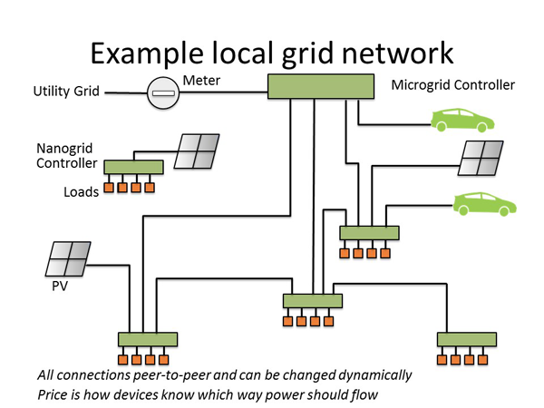
Microgrids can enhance systems efficiency by allowing for dynamic interactions among distributed energy resources, the utility grid, and loads. Credit: Nordman, B., Khandekar, A., Spears, M., & Pezzola, M. (2017). Lawrence Berkeley National Laboratory. A Simulation of Local Power Distribution Control Strategies, presented at Second International Conference on DC Microgrids, Nurnburg, Germany, 2017.
System Efficiency Applications
Several building systems can reduce energy consumption through improved controls , thermal exchanges, and multi-systems integration. While these measures may be easier to apply to new construction and major renovations, the majority of savings potential lies in changes to existing buildings. Opportunities for systems solutions in existing buildings are often associated with control systems installation or upgrades, interior renovations to accommodate new tenants, and end-of-life replacement of HVAC and other mechanical systems. Following are some examples of system efficiency measures:Lighting and Daylighting Systems
Energy used for lighting represents about 10 percent of commercial building electricity use. As defined by NEMA, an optimal lighting system is "a collection of luminaires and related lighting equipment installed in an application to provide the right amount of light where and when needed, with consideration of human comfort, visibility, safety and security, the physical environment, and daylight integration." Although energy efficient lighting components are critical, effective lighting and daylighting system design and controls can add significant energy savings. A lighting controls study in two GSA federal office buildings with updated LED lighting resulted in measured savings of 32-33 percent of lighting energy.
HVAC&R Systems
Energy used for HVAC&R systems represents over 50 percent of commercial building electricity use. HVAC&R systems (space cooling, space heating, ventilation, and refrigeration) are by far the largest users of energy in commercial buildings. In order to Optimize Energy Use, designers must consider specifying efficient HVAC systems, including efficient water— or air—based distribution, variable—speed controls, demand—based ventilation and heat or enthalpy recovery. Many potential sources of low-level heat, such as heat rejected from HVAC or refrigeration systems or from telecom and server rooms, could be captured for beneficial use in pre-heating hot water systems or to condition outside ventilation air.
Hot Water Systems
Building designers should prioritize the design of hot water distribution systems (e.g., pipe layout and the location of the heating system relative to points of use) to minimize the total heat lost while serving the load.
Motor Systems
Shifting to a systems approach that considers additional factors such as drivetrains, inverters and electronic drive controls—as well as the choice of motor—driven system components (e.g., for pumps and air—handlers)–has the potential to substantially increase the efficiency of the total motor system.
Miscellaneous Electric Loads
Miscellaneous electric loads (MELs) together currently account for about 28 percent of primary energy in commercial buildings, and in some high-efficiency buildings, over 50 percent of the electric load. According to DOE,
"…the amount of energy savings from replacing an individual device often does not justify the replacement cost. As a result, there is a need for developing overarching technological solutions that can achieve crosscutting reductions in energy consumption at minimum cost. Instead of targeting individual MELs, R&D advancements require going up one level (to systems of MELs) or down one level (to common MELs components)".
Strategies to reduce MELs include:
- Energy reduction at the device level by improving device efficiency
- Enhanced control of an individual device to reduce standby power
- Integration of MEL device controls with system-level sensors and controls and with other building systems to optimize building operation
Multi-systems Integration
To maximize whole-building efficiency we must recognize that buildings are made up of multiple systems and optimize their integrated performance. Integrated systems provide the controls and feedback needed for buildings to operate at peak efficiency.
Direct Current (DC) Power
As a multi-systems strategy, direct current power distribution within a building can reduce energy demand as well as contribute to grid balancing, expanded control options, and improved safety and reliability. DC distribution can deliver systems-oriented energy savings for lighting, MELs, and many HVAC&R components by:
- Reducing alternating current-to-DC (AC/DC) conversion losses and AC/AC transformer losses, in both active and "standby" modes.
- Making it more feasible to replace AC-driven devices with "native-DC" devices for computers, telecommunications, and consumer electronics, as well as for lighting, control systems, and motors (especially those in variable-load applications).
- Enhancing the value of native-DC on-site photovoltaic generation and battery storage by avoiding conversion losses.

Emerging opportunities for attaining significant efficiency gains-such as through the integration of smart grid connectivity and related control technologies-are optimally applied at the system level.
A Building Integrated Photovoltaics (BIPV) System is one example of an opportunity for DC distribution. Implementation of a BIPV system in combination with energy storage has the potential to reduce a building's billed energy charges by 42% – and DC distribution can provide further savings by avoiding multiple DC/AC/DC conversions.
Multi-building Systems: CHP and DES
Better integration of energy systems applies both within and outside the building boundary. Examples include Combined Heat and Power (CHP), District Energy Systems, and Buildings-to-Grid Integration.
Combined Heat and Power (CHP)
CHP systems have the potential not only to save energy and reduce building operating costs but also to enhance building operational resilience and grid reliability ("Valuing Resiliency: How Should We Measure Risk Reduction?"). In addition to the potential direct energy savings from CHP (such as doubling the useful energy products derived from fuel used, there are three categories of CHP "resilience value":
- Continued operation during major (low-probability/high-consequence) events;
- Power reliability under routine conditions; and
- Improved power quality
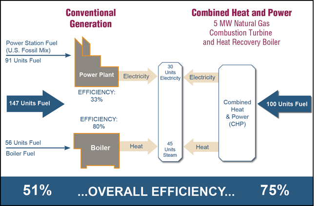
Combined Heat and Power (CHP) systems have the potential not only to save energy and reduce building operating costs but also to enhance building operational resilience and grid reliability. Credit: US EPA, Combined Heat and Power Partnership.
District Energy Systems (DES)
District energy systems can often improve energy productivity and energy diversity while reducing GHG emissions. According to the UN Environment Program, DES can reduce heating and cooling energy in urban buildings by as much as 30-50 percent . District energy is intrinsically open to diverse fuel sources on the thermal side; when combined with CHP it can diversify the source of both electricity and heat. DES systems can also be readily incorporate ice storage tanks to offset peak demands or to make better use of surplus generation from intermittent wind and solar resources. For the estimated 290 district energy systems in the U.S. that do not currently use CHP, conversion to CHP represents a tremendous opportunity for efficiency improvement .
Related/Emerging Issues
Developing System Metrics
Current metrics and regulations typically address rated equipment efficiency or whole-building performance as designed, but most do not address actual performance of equipment or buildings as installed and operated - although recent initiatives on outcome-based performance pathways represent a promising new direction.
New systems-level metrics, standards and tools could support the improved performance of building systems through system design and commissioning, in ways that consider typical building load profiles, operating patterns and regional climate conditions.
Systems Strategies for Existing Buildings
With about 5.6 million commercial buildings as of 2012 with expected lifetimes of several decades, it is clearly important to develop system-oriented retrofit strategies for the existing building stock as well as new construction. In existing buildings, integrated system retrofits can be implemented through a variety of approaches. These include:
- Retro-commissioning
- Controls retrofits to existing systems
- Building renovation
- Deep retrofits or sequenced planned retrofits
Systems Solutions for Smaller Buildings
As with the existing building stock, smaller commercial and residential buildings pose a special challenge to systems efficiency. Efficient systems solutions often require detailed energy modeling and design analyses, which are seldom cost-effective for smaller buildings. Thus, new approaches such as "packaged" system solutions need to be developed.
Reliability and Resiliency
As discussed above, efficiency gains in systems within the building (HVAC &R, lighting, MELs, etc.) and those outside the building such as CHP and DES all represent opportunities to reduce stress on the utility grid during peak demand periods and in case of unforeseen generation, transmission, or distribution outages, thereby enhancing the grid's reliability and resiliency. Emerging opportunities for Building-to-Grid (B2G) Integration offer the prospect of improved operational savings and reliability on both sides of the meter.
The evolution of a fully integrated, transaction-based building-grid and ecosystem will create new opportunities for optimizing system efficiencies, reliability and cost-effectiveness at both the building and grid scale, while paving the way for more effective integration of renewable resources and electric vehicles.
DOE's Grid Modernization Laboratory Consortium (GMLC) is working towards creating a next-generation grid operating system using grid-level integration of Energy Management Systems (EMS), Distribution Management Systems (DMS), and Building Management Systems (BMS), resulting in operations with less reserve margin and dramatically enhancing the energy and economic efficiency of the system. Systems integration and improved control systems (for example, GMLC's "Multi-scale Integration of Control Systems" also can lead to building improvements that have many other associated energy and non-energy benefits, including improved comfort, lower cost, and better integration of microgrids and distributed energy resources (e.g., solar PV, wind energy).
Relevant Codes, Standards, and Guidelines
- ANSI/ASHRAE/IES/USGBC Standard 189.1-2014, Standard for the Design of High-Performance Green Buildings
- ANSI C137.1, Lighting Systems
- Energy Star, certification for your building
- LEED Building Certifications
- LEED BD+C: Core and Shell Development — Green Building Council. This certification program provides incentives for systems efficiency as follows:
Additional Resources
Tools, Policies, and Ongoing Research that Support, Systems Efficiency
- Army Net Zero Initiative – U.S. Department of Defense. This initiative is a strategy for managing existing energy, water, and solid waste programs with the goal of exceeding minimum targets, where fiscally responsible, to provide greater energy and water security and increase operating flexibility.
- Energy Performance of Buildings Directive – EU of the European Parliament and of the Council. European legislation covering the reduction of the energy consumption of buildings.
- Implementing an Outcome-Based Compliance Path in Energy Codes: Guidance for Cities – National Institute of Building Sciences and New Building Institute. This report can be found on the Whole Building Design Guide's webpage titled Outcome-based Pathways for Achieving Energy Performance Goals.
- MotorMaster+ – U.S. Department of Energy. MotorMaster+ enables industrial energy coordinators, facility managers, and plant electricians to manage their motor inventory and maintenance logs in order to evaluate their energy efficiency and discover new ways to reduce energy use, thereby cutting costs and eliminating environmental impact.
- Performance Excellence in Electricity Renewal (PEER) – Green Business Certification Inc. This rating system for utility system energy efficiency and environment includes an incentive for Systems Energy Efficiency.
- S. 1874, Distributed Energy Demonstration Act of 2017 – Bill introduced by Senator Wyden.
- S. 1875, Flexible Grid Infrastructure Act of 2017 – Bill introduced by Senator Wyden.
- S. 1876, Reducing the Cost of Energy Storage Act of 2017. – Bill introduced by Senator Wyden.
- Savings by Design – California Utilities and Public Utilities Commission. This program offers incentives for building owners and design teams to take a systems efficiency approach.
- Smart Readiness Indicator for Buildings – VITO NV. This study provides technical support to the Directorate-General for Energy of the European Commission regarding potentially setting up a 'Smart Readiness Indicator (SRI) for Buildings'. SRI would give recognition for smarter building technologies and functionalities which enhance the energy efficiency and other pertinent performance characteristics of the building stock.
- Systems Program Manuals and Assessment Methods – Lawrence Berkeley National Laboratory. These program manuals allow the user to go "beyond widgets" by taking a systems level approach to realize deeper energy savings.
- VOLTTRON Controller for Integrated Energy Systems to Enable Economic Dispatch Improve Energy Efficiency and Grid Reliability – Grid Modernization Laboratory Consortium. This project will design, develop, field test, and commercialize a multi-purpose controller and associated open-source algorithms that will ensure real-time optimal operation, increase electric grid reliability, and lead to the goal of clean, efficient, reliable and affordable next generation integrated energy system (IES).
References
- 2012 Commercial Buildings Energy Consumption Survey: Energy Usage Summary, Table 5., U.S. Energy Information Administration (EIA), 2012
- Annual Energy Outlook, U.S. Department of Energy (U.S. DOE), 2015
- ANSI C137 Lighting Systems Committee, National Electrical Manufacturer Association (NEMA)
- Building Energy Codes Program: National Benefits Assessment, 1992-2040, by Livingston, O.V., P.C. Cole, D.B. Elliot, and R. Bartlett. Rep. no. PNNL-22610 Rev 1. Prepared for the U.S. Department of Energy. Oak Ridge, TN: Pacific Northwest National Laboratory, 2014
- Buildings Energy Efficiency Frontiers & Innovation Technologies (BENEFIT)-2017 Funding Opportunity Announcement (FOA) Number: DE-FOA-0001632, by the U.S. Department of Energy (U.S. DOE) 2016
- District Energy in Cities-Unlocking the Potential of Energy Efficiency and Renewable Energy, by the UN Environment Program (UNEP), ND
- Enhancing Community Resilience through Energy Efficiency, by Ribeiro, D., Mackres, E., Baatz, B., Cluett, R., Jarrett, M., Kelly, M., and Vaidyanathan, S.. ACEEE, October 2015
- Energy Savings Potential and Research, Development, and Demonstration Opportunities for Commercial Building Heating, Ventilation, and Air Conditioning Systems: Final Report. Navigant report for DOE, by Goetzler, W., R. Zogg, H. Hiraiwa, J. Burgos, and J. Young. 2011
- Green Buildings Matter, by Moore, Michelle. The American Prospect, 17 December 2006.
- Impacts of Commercial Building Controls on Energy Savings and Peak Load Reduction, by Pacific Northwest National Laboratory, May 2017
- Loads Providing Ancillary Services: Review of International Experience, by Heffner, G., C. Goldman, B. Kirby, and M. Kintner-Meyer. May 2007
- Miscellaneous Energy Loads in Buildings ACEEE Rep. no. A133, by Kwatra, S., J. Amann, and H. Sachs. [http://aceee.org/research-report/a133] 27 June 2013
- Reducing Plug and Process Loads for a Large Scale, Low Energy Office Building: NREL's Research Support Facility, By "Lobato, C., S. Pless, M. Sheppy, and P. Torcellini. 2011 (b). NREL/CP-5500-49002. Oak Ridge, TN.
- A Post-Occupancy Monitored Evaluation of the Dimmable Lighting, Automated Shading, and Underfloor Air Distribution System in The New York Times Building, by Lee, E.S., L.L. Fernandes, B. Coffey, A. McNeil, R. Clear, T. Webster, F. Bauman, D. Dickerhoff, D. Heinzerling, and T. Hoyt. LBNL-6023E. January 2013
- Quantifying National Energy Savings Potential of Lighting Controls in Commercial Buildings, by Williams, A., B. Atkinson, K. Garbesi, and F. Rubinstein. ACEEE, 2012
- Recognizing the Value of Energy Efficiency's Multiple Benefits. Research Report IE1502, by Russell, C., B. Baatz, R. Cluett, and J. Amann. American Council for an Energy-Efficient Economy, 2015
- Saving Water in Office Buildings, by the U.S. Environmental Protection Agency (EPA), January 2017
- Smart Tools in a 111d Toolbox: Combined Heat and Power and District Energy, by the International District Energy Association (IDEA). N.D.
- Solar + Storage Synergies for Managing Commercial-Customer Demand Charges, Slide #13, by Gagnon, P. et al. 2017
- The U.S. Appliance Standards Program (a), by the U.S. Department of Energy (U.S. DOE), April 2015
- Valuation of Transactive System, by Pacific Northwest National Laboratory, May 2016
- Valuing Resiliency: How Should We Measure Risk Reduction? Proceedings of the 2016 ACEEE Summer Study on Energy Efficiency in Buildings, by Chittum, A. Asilomar, CA: August 2016
- Windows and Offices: A study of worker performance and the indoor environment, Prepared by Heschong Mahone Group Inc. California Energy Commission, 2003
- Wireless Advanced Lighting Controls Retrofit Demonstration, by Wei, J., F. Rubinstein, J. Shackelford, and A. Robinson. Lawrence Berkeley National Laboratory. Rep. no. LBNL-183791, April 2015
Building Types
Bullitt Center
General Information
Building Name: The Bullitt Center Bulding Location: Seattle, Washington,United States Construction Type: New Construction (including public and academic buildings) Size: 52,000sf Market Sector: Private Building Type: Office Delivery Method: Integrated Project Delivery Total Building Cost: $30 million Project Completion Date / Date Building Occupied: April 2013
Cardiovascular Laboratory Service
The Cardiovascular Laboratory Service Design Guide (PG-18-12, Chapter 210) was developed as a design tool to assist the medical center staff, VACO Planners, and the project team in better understanding the choices that designers ask them to make, and to help designers understand the functional requirements necessary for proper operation of this procedure suite.
This document is intended to be used as a guide and is supplementary to current technical manuals, building codes and other VA criteria in planning Healthcare Facilities. The Design Guide is not to be used as a standard design; it does not preclude the need for a functional and physical design program for each specific project.
Case Studies
Department of Energy (DOE) - Industrial Technologies "Save Energy Now" (SEN) Program
Energy is often one of the most costly components of operating any manufacturing facility and its processes. A reduction in energy consumption reduces cost. Without exception, this is a continual objective of most companies. It may not be at the top of the list, but certainly within the top ten of corporate initiatives. While insulation can be one of the easiest, fastest and least costly "technologies" to reduce energy cost, it is often the last option considered.
It is interesting to review the process for determining the design criteria for insulation on new construction or expansion projects verses the maintenance process and how priorities are established. In new construction, the primary driver in determining the insulation system is the process. Very seldom is the insulation system or thicknesses examined from an energy conservation perspective. Once a facility or plant is operating and the energy consumed is a reality, as opposed to a theory, it seems that compliancy or acceptance of the results outweighs examining actual results in comparison to original expectations. Properly and timely maintaining an insulation system seems to mostly reactionary verses proactive.
It has been estimated that between 10—30% of all installed mechanical insulation is either damaged or missing. The question that must be asked is why does this condition exist when it can be corrected and provide a significant return on the capital employed or maintenance dollars expended?
The Department of Energy (DOE) - Industrial Technologies, "Save Energy Now" (SEN) Program is part of a national campaign by the DOE to help manufacturing facilities reduce energy and operating costs and operate more efficiently and profitably. Independent specialists who have been trained in the utilization of sophisticated software assessment tools and have passed a rigorous qualifying exam, visit a plant and work with personnel to identify immediate and long-term opportunities for improving energy efficiency and bottom-line results. Mechanical insulation is one of the many opportunities that are examined.
Of the SEN assessment studies published to date (September 07), 53% have identified replacing, repairing and upgrading the mechanical insulation as an opportunity of which 84% have estimated a return on investment in less than a year.
Following are but a few example excerpts from the SEN survey results which are classified as "near term" opportunities—payback in less than one year: (Assessment results determined by review and interpretation of available data. (Please refer to the Save Energy Now web site, www.eere.energy.gov/industry/saveenergynow, for specific and detailed information on these and other examples. The information shown does not depict all aspects of the reported assessment results for the respective facility)
Bayer (2 Steam Plants), Institute, WV
By improving and replacing missing insulation on the steam and condensate lines - Potential savings $926,000 per year
Boise Cascade (Paper Mill), Jackson, AL
By replacing missing pipe insulation - Estimated savings $80,000 per year, cost to complete the work $25,000 = 3.8 month payback
Dow Chemical (Chemical Plant), Hahnville, LA
By replacing, repairing and improving insulation on steam system - Potential annual savings of $811,000
General Motors (Power Plant), Pontiac, MI
By replacing missing insulation and repairing other areas - Estimated annual savings of $298,000
Goodyear, Union City, TN
A significant number of process units are partially insulated. Potential savings, $402,000 per year. Estimated payback 2.5 to 6 months depending upon cost of completing the work. "This same opportunity can be applied to other company facilities."
National Starch (Power Plant), Indianapolis, IN
By replacing and repairing insulation - Estimated annual savings of $125,000
Sterling Chemical (Chemical Plant), Texas City, TX
Improvements in the insulation - Potential annual savings of $123,000
Mead Westvaco, Silsbee, TX
Commissioned an "Insulation Strike Team" to go through the plant to repair areas of poor, damaged or missing insulation. They determined that reducing insulation heat loss by 10% would yield savings of over $486,000 per year
United States Steel, Gary, IN
Estimated that by using proper type, size and thickness of insulation and improving maintenance of the insulation systems could result in annual savings in excess of $1,500,000 per year
Mittal Steel, Weirton, WV
By insulating hot water washing tanks, 140 F operating temperature, located throughout the facility, 50,000 SF of surface area, with an inexpensive - simple insulation system the annual savings would be $371,000 + per year
Eastman Chemical, Kingport, TN
"The thermal insulation system throughout the site is observed to be in good condition...several pipes observed to be missing insulation. The approach taken in investigating and illuminating insulation issues is excellent and considered to be a Best Practice approach"
One heat tracing system is not completely evaluated yet - identified savings $1,000,000 with re-insulation cost of $300,000 = 4 month ROI
Steam system will be evaluated - preliminary investigation indicate a potential savings of additional $1,000,000 with return ranging from 1 to 3 years
"Improving From the Outside In" Insulation upgrades to the outside pipelines at NOCO Energy Corporation improve energy efficiency-and the company's bottom line.
NOCO Energy Corporation has a large terminal operation outside of Buffalo, New York, in Tonawanda. From that terminal, NOCO distributes petroleum and petroleum products to the western New York area. Among the petroleum-based products that NOCO distributes are asphalt and No. 6 fuel oil, which must be kept in heated storage tanks and distribution pipelines. Without heated tanks, piping, and equipment, these products cannot be pumped.
Multiple Challenges To Meet
Over the years, it became increasingly difficult for NOCO to maintain adequate temperatures in storage tanks and pipelines. This resulted in slow pumping and transfer rates through the pipelines, as well as periodic plugging. These problems made it difficult to run the terminal efficiently and cost-effectively.
NOCO's location along the shore of Lake Erie in western New York did not help. Winter temperatures can reach -20°F, annual snowfall surpasses 90 inches, and winds average 12 miles per hour (mph), with peak winds well over 50 mph. These severe factors made maintaining sufficiently high operating temperatures more difficult—and even more critical.
The situation was aggravated further by the terminal layout. It is spread out, requiring long pipelines from the lakefront barge-loading facilities and the storage tanks. Additionally, the terminal used a heated-oil heat transfer fluid to maintain the temperatures in the storage tanks and pipelines, with the heaters located at the northern end of the terminal. This also made for long heated-oil transfer lines.
The final problem was the terminal's damaged insulation systems, especially on the product pipelines and heated-oil supply lines. All of these lines are located in ground-level horizontal pipe racks. Over the years, between people stepping on the pipelines, maintenance activity, and the effect of the Buffalo-area weather, the insulation systems degraded. The systems' poor condition contributed significantly to the terminal's difficulty maintaining temperature in the asphalt and No. 6 fuel oil tanks and pipelines.
First Solutions First
Revision of the heated-oil transfer system was the first priority. Management submitted a project to design and install another heated-oil heater, located toward the southern section of the terminal. Revising the system would improve heat transfer and pumping efficiency.
The terminal staff believed upgrading the insulation systems would improve the overall reliability and efficiency of the systems, as well as save on energy costs. With the help of the New York State Energy Development and Research Authority (NYSERDA)—see "NYSERDA Offers Energy-Saving Expertise"—and the engineering firm Clough, Harbour, & Associates, they performed an evaluation of all of the insulation systems and determined the economic impact of upgrading all affected insulation systems, including the addition of 2 inches of insulation to the existing 2 inches. Because the terminal had a readily available, low-cost fuel source for the heated-oil heaters in used motor oil, the initial evaluation indicated an unusually long payback period for an insulation upgrade project like this—around 3 years.
An Unexpected (and Lucrative) Turn of Events
About the time the original assessment was performed, terminal staff found that the used motor oil being used for fuel in the heated-oil heaters was in greater demand. So any fuel saved from burning in the heated-oil heaters could be sold profitably. This increased interest in the insulation upgrade.
The new heated-oil heater was installed, but only some of the insulation was upgraded for several reasons, including schedule, equipment availability, and budget. Part of the problem was the fact that the insulation systems were much more damaged than originally assumed and had to be completely replaced.
Because the addition of the new heated-oil heater and some rerouting of heated-oil lines were projected to actually increase fuel consumption and cost to the terminal, it became more complex to analyze the benefit of the insulation upgrade project to the overall facility.
Through the efforts and resources of NYSERDA, a review of the work and an analysis of the energy savings on the upgraded insulation systems were performed using both proprietary and 3E Plus® software (see "The Power of 3E Plus"). The following are the results of the analysis:
- Projected energy savings of approximately 10 billion Btus per year or more than $87,000
- Projected used motor-oil savings (that can be sold in the marketplace at approximately $1 per gallon) of around 87,000 gallons
- Projected payback: slightly more than 1 year
- Carbon dioxide (CO2) reduction: more than 2.3 million pounds of this greenhouse gas per year
- More than 4,500 pounds of nitrogen-oxygen compounds (NOx) class of regulated emissions, which includes both greenhouse gases and other gases that influence the mixing ratio of greenhouse gases
"Though it is difficult to quantify the fuel savings that resulted from this project, the original heating system was grossly undersized for our needs," says Val Speek, terminals and facilities manager at NOCO Energy Corporation. "Burners were running at a 100-percent firing rate and were unable to meet the Btu demand for heating our asphalt. The addition of a new thermal fluid heater and the replacement of damaged insulation resulted in a surge of customer satisfaction. The heater played a major role in maintaining our marketing tanks at an acceptable temperature, while the replacement of damaged line insulation increased efficiency and eliminated customer complaints of cold asphalt".
"This is the first year I can remember having no problems loading asphalt in the cooler weather," Speek adds.
Paul D. Tonko, NYSERDA's president and chief executive officer (CEO), says, "Through NYSERDA's FlexTech program, we've assisted NOCO in operating its distribution terminal more efficiently while maintaining profitability. Our study of the facility identified significant areas of energy-efficient infrastructure and productivity improvements to the rail facility, heat transfer system, tank farm, and pump motors. As a result, NOCO's $5-million capital investment has led to $500,000 per year in energy and productivity benefits, 16 indirect jobs, and the equivalent of 20,000 barrels of oil saved annually. NYSERDA is proud to have partnered with NOCO Energy Corporation and Clough, Harbour, & Associates in making the necessary energy efficiency upgrades at the facility."
Even better than the projected cost savings and emission reductions from energy efficiency is the fact that the properly insulated lines now pump product easier and faster, with far fewer plugging problems, allowing the terminal to operate more efficiently and profitably. The facility's overall result is a win-win situation—a better-running terminal, more recycled motor oil to sell rather than burn in the heated-oil heaters, and less environmental impact due to fewer greenhouse gas emissions.
The Power of 3E Plus®
The 3E Plus® software program from the North American Insulation Manufacturers Association (NAIMA) is an invaluable industrial energy management tool that can be used to calculate energy savings and determine the most energy-efficient use of insulation. It also helps users—including facility managers, energy and environmental managers, industrial process engineers, and industrial plant managers—reduce plant emissions, improve system process efficiency, and determine return on investment (ROI) of insulation upgrades.
3E Plus is designed to allow users to calculate heat losses and determine surface temperatures on hot and cold piping, as well as equipment. The program can:
- calculate the thermal performance of both insulated and uninsulated piping, ducts, and equipment;
- translate British thermal unit (Btu) losses into actual dollars; and
- calculate greenhouse gas emissions and reductions.
The latest version of 3E Plus can be downloaded for free at Pipeinsulation.org. The program includes thermal conductivity curves from ASTM Material Specifications for most insulation types. Users have the option of inputting thermal data from other sources, if desired.
Learn how to use 3E Plus effectively by taking the National Insulation Association's (NIA's) Insulation Energy Appraisal Program (IEAP), which is a fully accredited certification program. For more information, please visit www.insulation.org/training/ieap.
NYSERDA Offers Energy-Saving Expertise
The New York State Energy Research and Development Authority (NYSERDA) was established by a 1975 law as a public benefit corporation. It is devoted to using innovation and technology to solve some of New York's most challenging energy and environmental problems in ways that improve the state's economy. NYSERDA offers sophisticated energy-efficient construction advice, services, and funding for new construction and rehabilitation improvements. Its efforts are concentrated largely on improving the environment, especially in relation to the emissions associated with the generation and consumption of energy.
Since 1990, NYSERDA has successfully developed and brought into use more than 170 innovative, energy-efficient, and environmentally beneficial products, processes, and services. It works with hundreds of businesses, schools, and municipalities to identify existing technologies (such as insulation) and equipment to reduce energy costs.
For more information on NYSERDA and its energy-saving efforts, please call 866-697-3732 or visit www.nyserda.org.
Case Study conducted by Michael Lettich. Mike Lettich is the principal consultant of MJL Consulting, where he helps the chemical, petroleum, pharmaceutical, pulp and paper, utility, and other industries improve their maintenance programs. He consults in insulation, coatings, and contractor effectiveness. A chemical engineer, he previously worked for DuPont, from which he retired after 28 years. While at DuPont, he helped implement the Thermal Insulation Maintenance Service® (TIMS®), providing strategic, focused, cost-effective insulation maintenance programs in industry.
Georgia-Pacific Reaps Benefits by Insulating its Steam Lines
Insulation upgrade program reduces fuel costs and increases process efficiency at Georgia-Pacific plant
Built in 1979, the Georgia-Pacific plant at Madison, Ga., uses Loblolly pine to manufacture plywood. The tree is abundant in the area. Most of the trees harvested are within a 180- mile radius of the mill. About 20 percent of the trees are grown on land owned by Georgia-Pacific and about 80 percent come from other privately owned land. The plant runs 24 hours, 7 days a week and employs approximately 400 people.
The process of making the veneer layers in a plywood panel begins when logs arrive at the mill in sections. They are immediately debarked and soaked in water at 180°F for six hours. This softens the logs and enables them to peel better. The softening process also allows the logs to pass through the lathe much easier and delivers the veneer layers at the right temperature to the dryer where they are dried at temperatures of 405°F.
From the dryers, the veneer layers go to the glue line where layers are sandwiched with glue and then pressed into a panel. From there the panels go to the saw line for trimming before banding and shipping.
Because the steam lines to the dryer were uninsulated, heat was radiating out and millions of Btu were being lost. The heat loss resulted in a loss of pressure and a reduction in temperature as the plywood moved down the line. The increased drying time needed slowed the process down significantly.
While Georgia-Pacific wanted to insulate the steam lines for energy conservation, improved process efficiency and personnel protection, the company also wanted the insulation for a more pragmatic reason—to eliminate dependence on purchased fuel. The plant normally uses wood bark and wood byproducts for fuel. However, at certain times of the year the bark is too thin for use as adequate fuel so additional fuel had to be purchased from an outside source.
Determining the Thickness of Insulation
Once the decision was made to insulate the steam lines, a computer program called 3E Plus created by the North American Insulation Manufacturers Association (NAIMA) was used to determine the insulation thickness required to insulate the 1,500 feet of saturated steam lines with temperatures operating at 437°F.
Computer projections estimated that insulation would significantly reduce the heat (Btu) loss along the steam lines leading to the dryers. This reduction in heat loss alone could increase the operating temperature by 15° and maintain the process temperature along the length of the lines. The combination of a higher temperature in the dryer lines and a more consistent process line temperature would result in a faster and more efficient veneer plywood process.
The Madison plant installed two-inch thick fiber glass pipe insulation. Two inches is the thickness needed to reduce heat loss, maintain process temperature and bring the outside surface temperatures of the pipes down for personnel protection. Insulation footage was as follows: 120 feet of insulation on the twelve-inch process line; 200 feet on the eight-inch process line; 220 feet on the six-inch process line; 80 feet on the four-inch process line; and 350 feet on the 1-1/2-inch process line.
A major advantage of using mineral fiber insulation to insulate the steam lines was that no downtime was required. Several areas that could not be insulated while the line was running were insulated on schedule down days. Says Jackson, "We do dryer maintenance once a week so the dryer is shut down during that time. That's when the insulation was installed on those areas that couldn't be accessed while the dryer was running."
Immediate Results
The personnel at the Georgia-Pacific plant were pleased with the results of the insulation project.
Improved Process Efficiency
The lines to the mill's four dryers have all been insulated, and according to Darryl Jackson, boiler superintendent at the Madison plant, "Gauging the increase in throughput has proven to be a bit more complex than we first thought. A more accurate gauge of the effectiveness of the insulation is the steam usage. The insulation has allowed us to cut our steam usage by approximately 6,000 lbs./hour. This is equivalent to saving about 18 tons of fuel per day. I can track these numbers with a totalizer so I know exactly what the dryers are pulling at any given time."
Dependence on Outside Fuel Eliminated
By insulating the piping, Georgia-Pacific has been able to eliminate the purchase of fuel. Says Jackson, "Currently we are selling some of our excess fuel to a paper company."
Reduction in Pollutants
By reducing fuel consumption, the Madison plant has been able to reduce the amount of ash being generated and estimates that the energy saved through insulation has reduced the amount of C02 emissions by 5 to 6 percent.
Increased Personnel Protection
Prior to installing the insulation, the piping in the Madison plant had a surface temperature of approximately 400°F. With insulation, the surface temperature has been reduced to approximately 85°F—a safer level for personnel protection.
In addition to insulating the steam lines, Georgia-Pacific also replaced 70 steam traps. According to Jackson, "We've probably gained 10 percent condensate return from replacing the thermal dynamic traps. By increasing the condensate by 10 percent, our savings will be approximately $86,000 per year based on an $8 per ton fuel cost".
Georgia-Pacific estimates that the amount of energy saved by insulating the steam lines to the dryers and installing new steam traps is approximately 7,212,000 Btu per hour.
Payback on Initial Investment
Calculating how long it takes to pay back an initial insulation investment is an integral part of Georgia-Pacific's energy management program. Based on the results realized, the payback period at Madison was approximately six months
This case study appeared in the March 1998 issue of Insulation Outlook, published by the National Insulation Association
Cast-in-Place Concrete Wall Systems
Introduction
Within This Page
The Executive House in Chicago is generally known as the first reinforced concrete skyscraper. At the time of it's completion in 1959, it was the tallest reinforced concrete building in the United States at 39 stories, or 371 feet. In 1962, the twin towers of Marina City in Chicago set a new record at 588 ft above grade. These distinctive circular, reinforced concrete towers also served as an early example of a cast-in-place concrete wall system. Subsequently, Chicago's Lake Point Tower built in 1968 and Houston's One Shell Plaza built in 1970 set new records at 645 ft and 714 ft, respectively. While both of the latter buildings are clad in materials other than concrete, their innovative structural systems are reflected in their façades and established the precedent for many of the cast-in-place concrete wall systems seen throughout the United States.
Description
A cast-in-place concrete wall system is an exposed structural system that also serves as the façade. Openings or penetrations in the structural system are generally infilled with windows, masonry, or some other cladding material.
Fundamentals
Cast-in-place concrete wall systems are generally defined by the building's structural system, which consists of the vertical (gravity) load resistant system and the lateral (wind and seismic) resistant system. The vertical load resistant system may be further subdivided into the horizontal framing (floor system) and the vertical framing (column and walls). The lateral resistant system includes moment resisting frames, shear walls, braced frames, or a combination of these systems.
A concrete structure designed and constructed in the United States is governed by the minimum provisions of the ACI Building Code. While most of the design provisions of the Code dictate minimum strength (safety) requirements, the Code also prescribes serviceability and durability requirements. Certain factors which influence the design of the structural system also impact the exterior wall. These factors include deflection, cracking, concrete cover, and corrosion protection.
Performance Issues
Thermal Performance
Cast-in-place concrete walls derive their thermal performance characteristics primarily from the amount of insulation placed in the cavity or within the backup wall.
Moisture Protection
The most common moisture protection system used with cast-in-place concrete wall systems is a barrier system incorporating an adequate joint seal. In some cases where additional moisture protection is needed, the application of a sealer or a concrete coating is also used. Sealers can be either clear or pigmented if used as an enhancement of the precast appearance. Film-forming coatings usually offer a higher level of performance but will have a significant impact on the appearance of the precast concrete unit.
The cast-in-place concrete wall should also be designed to provide the appropriate level of durability for the planned exposure. Durability can be improved by specifying minimum compressive strengths, maximum water to cement ratios, and an appropriate range of entrained air.
Fire Safety1
At relatively high temperatures experienced in fires, hydrated cement in concrete will gradually dehydrate, reverting back to water (steam) and cement. This results in a reduction in strength and modulus of elasticity (stiffness) of concrete that, in some instances, can result in spalling. The overall fire resistance of concrete is influenced by aggregate type, moisture content, density, permeability, and nominal thickness. "Carbonate" aggregates, such as limestone, dolomite, and limerock, have been found by some to improve the overall fire resistance of concrete due to their ability to absorb some of the heat from a fire. Similarly, concretes with lower unit weights (densities) will also offer improved fire resistance, as will dried light-weight concrete. In contrast, concrete with relatively low moisture content, low water-cement ratio, and highly impermeable concrete may spall when subjected to fire.
1Gustaferro, Armand H., "Fire-Resistant Concrete", MC Magazine Archive
Acoustics
A cast-in-place concrete wall system and precast concrete panel façade will provide similar performance regarding sound transmission from the exterior to the interior of the building. See Precast Concrete Wall Systems for additional information, as well as the industry and trade association web site links listed at the end of this section.
Material/Finish Durability
The key issue to be addressed in design of a cast-in-place façade element is durability related to environmental exposure such as moisture, carbonation of concrete, and other factors that can contribute to the distress and deterioration of concrete.
Concrete deterioration may occur for two principal reasons: corrosion of the embedded steel resulting in concrete deterioration, and degradation of the concrete itself. Concrete normally offers protection to embedded reinforcing steel through its alkalinity.
Concrete deterioration due to corrosion of embedded steel is usually related to moisture, and is typically in the form of cracking and delamination of the concrete. Where embedded reinforcing steel is not protected by the alkaline environment of the concrete, and the steel is exposed to moisture, corrosion occurs. The corroded steel expands significantly in volume, which results in expansive forces on the adjacent concrete, causing it to crack and spall. This is visually apparent in cracking and delamination of the concrete and rust staining at the location of embedded steel.
Carbonation results in the loss of alkalinity within the concrete to the level of the reinforcing steel. Carbonation normally occurs only in the vicinity of the exposed surface of the concrete, but in some cases may extend to the level of the steel. Once this occurs, the concrete offers no protection to the embedded reinforcing steel, and corrosion begins. Carbonation occurs from a combination of moisture and carbon dioxide.
Corrosion of embedded reinforcing steel is often due to calcium chloride added to the concrete as an accelerator during original construction or later from de-icing salts used in northern climates. Chloride ion in combination with moisture results in corrosion of the embedded steel and resulting deterioration of the surrounding concrete. Sea water, or other marine environments, provide large amounts of chloride.
The exposed surface of the concrete is also vulnerable to weathering from the elements. This may typically be observed as erosion of the concrete paste. Especially in northern regions where precipitation has been found to be highly acidic, exposure has resulted in more significant erosion of the paste on the exposed surfaces.
Freeze-thaw damage results from the freezing of concrete that is saturated with water. This type of damage appears as degradation of the surface, including severe cracking, extending into the concrete. It was accidentally discovered that portland cement concretes that incorporate microscopic air bubbles provided resistance to cyclic freezing and thawing. The air-entrainment provides "relief valves" that protect the concrete. Air-entraining agents are now generally (but not always) added to cement or concrete used in exposed applications that are in areas of the United States subject to sub-freezing temperatures.
Alkali-aggregate reactions result when alkalis normally present in cement react with silicious aggregates in concrete that is exposed to moisture. The reaction produces a toothpaste-like gel that develops over years or decades until the forces created expand and crack the concrete. Most such deleterious aggregates can be detected by experience or test, and low-alkali cements can be used in new construction to prevent significant reactions.
Sulfate attack is produced by the reaction of excessive amounts of sulfate salts with cement components that are exposed to moisture. The reaction leads to the development of expansive forces that eventually crack the concrete. The sulfate salts may come from the environment (e.g., sulfate waters or solids), or from one or more of the concrete constituents (e.g., aggregates, cement, or proprietary product providing fast set).
Other forms of concrete deterioration exist, including freeze-thaw damage, alkali-aggregate reaction and sulfate attack, but less common in cast-in-place concrete wall systems.
Maintainability
Durability of concrete and resistance to deterioration is dependent on durability, proper design, and good workmanship. This will also be true for the materials used to repair existing concrete. A mix design for durable replacement concrete should utilize materials similar to those of the original concrete mix and include air-entrainment, appropriate selection of aggregates, and adequate cement and water content. Good workmanship should address proper mix, placement, and curing procedures. In all cases, a good mix design will enhance good workmanship for durable repair concrete.
In designing repairs to existing concrete, parameters must be established to define the goals of the project based on visual evaluation and laboratory studies. A key concern is the aesthetics of the repair, to match the existing concrete as closely as possible both visually and structurally. Another governing concern is to select repair interventions that retain as much as possible of the original material; however, an adequate amount of distressed concrete must be removed to provide a durable repair.
All repairs of existing concrete require proper preparation of the substrate to receive the repair material. This typically includes sandblasting, airblasting, or other appropriate means to provide a clean surface to which the repair can adequately bond. Bonding agents are commonly used on the substrate surface to enhance the bond of the repair. Existing reinforcing steel that is exposed during the repair may require cleaning, priming, and painting with a rust-inhibitive coating. In most cases, the repair area should be reinforced and mechanically attached to the existing concrete. Reinforcement may be regular steel, epoxy-coated steel, or stainless steel, depending on the conditions.
Proper placement and finishing of the repair is important in achieving a match to the original concrete. Appropriate curing is essential for a durable repair; wet curing is recommended to reduce the time of curing and the potential for surface and shrinkage cracking.
The preparation of trial repairs and mockups to refine the repair design, and also to evaluate repair procedures is a wise procedure. Mockups also permit evaluation of the visual and aesthetic acceptability of the repair design.
Because concrete deterioration is primarily the result of moisture penetration, rehabilitation may also entail application of a decorative surface coating or clear penetrating sealer. These water-resistant coatings and sealers should be breathable and alkali-resistant.
Various repair methods and techniques are available in the market today to reduce the rate of corrosion of embedded reinforcing and associated deterioration of the concrete. One method is cathodic protection, which utilizes an auxiliary anode so that the entire reinforcing bar is a cathode. (Corrosion is an electro-chemical process in which electrons flow between cathodic (positively-charged) and anodic (negatively-charged) areas on a metal surface; the corrosion occurs at the anodes.) Cathodic protection is intended to reduce the rate of corrosion that occurs to embedded steel in concrete, which in turn reduces concrete deterioration.
Cathodic protection is only one of many evolving techniques available to protect concrete. Another technique currently available is realkalization, which involves returning the concrete to its natural alkaline state.
Applications
Cast-in-place concrete wall systems have been in use in the United States for many decades. Much of the early development of this construction type occurred in Chicago, primarily due to the influence of the Portland Cement Association and innovative structural engineers like Fazlur Khan. The permanence of this building type is evident by the number of prominent cast-in-place concrete buildings built in the 1950's and 1960's that still exist and remain functional today.
See Appendices for climate-specific guidance regarding building enclosure design.
Emerging Issues
Ordinances related to the maintenance of façades, including cast-in-place concrete wall systems, have been enacted in New York and Chicago. As the inventory of older buildings increases, the maintenance of these building façades and the life safety issues associated with their deterioration will also increase.
The mechanisms that generally contribute to the deterioration of cast-in-place concrete wall systems are well known. Improvements in design standards and repair technology will result in improved performance.
The necessity to make building envelopes blast-resistant has forced reconsideration of the cast-in-place concrete façade as a design option.
Relevant Codes and Standards
- American Concrete Institute ACI 318—Building Code Requirements for Structural Concrete
- American Concrete Institute ACI 301—Specifications for Structural Concrete
- Concrete Reinforcing Steel Institute (CRSI)—Reinforced Concrete Fire Resistance
Additional Resources
WBDG
Products and Systems
See appropriate sections under applicable guide specifications: Unified Facility Guide Specifications (UFGS), VA Guide Specifications (UFGS), DRAFT Federal Guide for Green Construction Specifications, MasterSpec®
Publications
Organizations
- American Concrete Institute (ACI)
- Autoclaved Aerated Concrete Product Association (AACPA)
- Concrete Reinforcing Steel Institute (CRSI)
- Concrete Homes Council
- Insulated Concrete Forms—EPS Industry Alliance
- Portland Cement Association (PCA)
Other
Cathodic Protection Knowledge Area
by Robert J. Evans Jr., P.E. (AFCEC) and Lean–Miguel San Pedro (NAVFAC) and Thomas Tehada, P.E. (NAVFAC) for the Director, Corrosion Policy & Oversight (DCPO), (DASD) [Materiel Readiness]
Updated: 10-07-2021
INTRODUCTION
Within This Page
Cathodic Protection (CP) is a technique used for prevention of corrosion by making a metal, which would ordinarily behave like an anode and corrode, instead behave like a cathode and reduce or eliminate corrosion attack. It is the application of the electrochemical corrosion cell with beneficial results. CP is generally accomplished using two methods: sacrificial anodes (providing galvanic CP (GCP)) (see Figure 1) and direct current (providing impressed–current CP (ICCP) (see Figure 2). CP System anodes transfer the location of the corrosion attack from the structure being protected to the anodes itself (another material specifically selected to make the CP circuit function).
For GCP system anodes to supply current, its electrochemical potential difference must be more electronegative than the structure protected. Sufficient potential difference must exist between them to overcome the circuit resistance to provide adequate current to achieve structure protection. Since GCP anodes provide protective current through the electrochemical corrosion process, they must also be low cost and have sufficient current capacity to be cost effective.
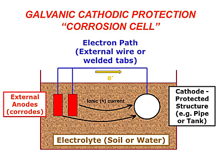
Figure 1: Schematic Illustration of a GCP System Source: Thomas Tehada, P.E., NAVFAC EXWC. Adapted from UFC 3-570-01 Cathodic Protection
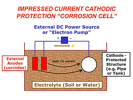
Figure 2: Schematic Illustration of an ICCP System Source: Thomas Tehada, P.E., NAVFAC EXWC. Adapted from UFC 3-570-01 Cathodic Protection
The most common GCP anodes are aluminum, magnesium, and zinc. In ICCP, a direct current from a power source through ICCP anodes is applied to the structure being protected to prevent the electrochemical mechanism of corrosion prior to its attack. ICCP system uses semi–inert anodes to supply protective current. These anodes exhibit relatively noble electrochemical potentials; therefore, to produce charged flow in the direction to cathodically protect a steel structure, it is necessary to connect an external power source. The power source must overcome galvanic potential difference between ICCP anodes and protected structure before it can even supply the first increments of protection to the structure. We often call that potential the power source must first overcome, back voltage. The most common ICCP anodes are graphite, high silicon cast iron, platinum, mixed metal oxide and polymer. Electrical energy used up in the transfer of charge across the respective cathode and anode/electrolyte interfaces causes this change in potential and we call it, polarization, which is critical in determination of meeting adequate protection criteria.
DESCRIPTION
CP systems must be carefully designed, correctly installed, inspected for proper function, certified to deliver adequate protection and maintained. Current NACE standards recognize adequate protection through three primary criteria for steel exposed to soil environments:
- –850mVCSE potential criteria with current applied
- –850mVCSE polarized potential
- 100mV polarization shift criteria
Aeration (oxygen), agitation (velocity), temperature, pH, surface area, and time affect polarization, potential measurements, and criteria validity. When designing or evaluating a CP system, the fundamental CP design objectives include:
- Providing sufficient, continuous current density to all parts of structure to acceptable criteria
- Minimizing interference effects to other structures
- Providing operational flexibility for expected changes in environmental, protective coating, and system service life
- Adhering to applicable codes and standards to ensure public and operational personnel's safety
- Providing CP system design life that coincides with the protected system's service life
- Providing testing and monitoring facilities to ensure CP system performance meet industry criteria, standards, and regulations
We ultimately confirm the effectiveness of a CP system by whether it controls corrosion or not. Determining corrosion rate directly is generally not a simple process. In most instances, we rely upon indirect methods of assessing CP system. The main method is the measurement of the structure to electrolyte potential as compared to the selected criteria. We also measure system currents as an additional performance parameter. We routinely measure structure to electrolyte potentials for compliance with these criteria and ensure meeting any regulatory standards. We must also take into account any of those factors that affect polarization, potential measurements, and criteria validity.
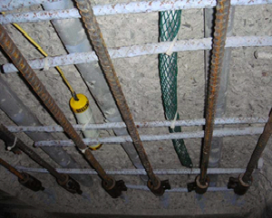
Photo 1: Discrete zinc anode (wrapped in green mesh) in concrete deck repair. The device with the yellow lead wire is a permanent reference electrode. Source: UFC 3-570-01 Cathodic Protection
Cathodic protection is utilized to protect critical infrastructure, much of which would have calamitous results due to failure:
- Natural gas piping and distribution systems
- Liquid fuel piping
- Oxygen piping
- Fire mains and underground fire protection piping
- Ductile iron pressurized piping under floor slab (slab on grade)
- Underground heat distribution and chill water piping in metallic conduit
- Steel sheet pile seawalls, pier support, fender piles, and other submerged steel structures
- Underground, ground level and elevated storage tank systems
Other systems that may employ CP:
- Systems with hazardous products
- Potable water distribution systems
- Compressed air distribution systems
- Sewage lift stations
- Concrete reinforcing steel

Photo 2: Periodic Performance Testing—Rectifier Output Current of ICCP System. Source: Steve Geusic, P.E, LEIDOS
A properly designed, operated, and maintained CP system can extend the life of a structure indefinitely with the replacement of CP components. The annual maintenance and periodic repair costs are far less than major repairs to or replacement of the structures themselves. The reduction of potential liability from premature failure of utilities such as gas line explosions and jet fuel leaks is enormous. Cost avoidance caused by the leakage that results in fines, environmental cleanup, remediation and disposal of contaminated soil along with the associated negative public image is an overarching consideration in selecting and sustaining a functioning and effective CP solution. For more information, review the Cathodic Protection Basics training module. The CPC Checklists Tool provides several design and field inspection reminders to ensure that CP meets requirements over the life cycle.
Relevant Codes and Standards
Department of Defense
Unified Facilities Criteria (UFC)
- UFC 1-200-01 DoD Building Code
- UFC 3-570-01 Cathodic Protection
- UFC 3-570-06 Operation and Maintenance: Cathodic Protection Systems
Unified Facilities Guide Specifications (UFGS)
- UFGS 26 42 13 Galvanic (Sacrificial) Anode Cathodic Protection (GACP) System
- UFGS 26 42 15 Cathodic Protection System for the Interior of Steel Water Tanks
- UFGS 26 42 17 Impressed Current Cathodic Protection (ICCP) System
- UFGS 26 42 19.10 Cathodic Protection Systems (Impressed Current) For Lock Miter Gates
U.S. Army Corps of Engineers - Public Works Technical Bulletin (PWTB)
- PWTB 420-49-29 Operation And Maintenance Of Cathodic Protection Systems
- PWTB 420-49-37 Cathodic Protection Anode Selection
Association for Materials Protection and Performance (AMPP) [National Association of Corrosion Engineers (NACE) and Society for Protective Coatings (SSPC)]
- SP0169 Control of External Corrosion on Underground or Submerged Metallic Piping Systems
- SP0285 Corrosion Control of Underground Storage Tank Systems by Cathodic Protection
- SP0388 Impressed Current Cathodic Protection of Internal Submerged Surfaces of Carbon Steel Water Storage Tanks
- SP0193 External Cathodic Protection of On-Grade Carbon Steel Storage Tank Bottoms
- SP0196 Galvanic Anode Cathodic Protection of Internal Submerged Surfaces of Steel Water Storage Tanks
ADDITIONAL RESOURCES
Organizations
- (AMPP) NACE Cathodic Protection Program provides multiple courses and certifications on cathodic protection and its technology, including, but not limited to:
- Cathodic Protection Tester (CP1), covering basic corrosion science and taking measurements from rectifiers and portable reference electrodes
- Cathodic Protection Technician (CP2), covering in–depth corrosion science and how to interpret CP–test readings for adequate CP and for determining problems with CP systems
- Cathodic Protection Technologist (CP3), covering troubleshooting and design calculations for CP systems
- Cathodic Protection Specialist (CP4), covering CP–system design
- (AMPP) SSPC (The Society for Protective Coatings) Training and Certification
- STI (Steel Tank Institute) Training and Certification
Assistance
DoD Installations Organizations
- Office of the Deputy Assistant Secretary of Defense (Construction)
- Engineer Research and Development Center, Construction Engineering Research Laboratory (ERDC-CERL)
- Air Force Civil Engineer Center (AFCEC)
- Naval Facilities Engineering and Expeditionary Warfare Center (NAVFAC EXWC)
Education
CDC Guidelines for TB Transmission Prevention
Guidelines for Preventing the Transmission of Mycobacterium tuberculosis in Health-Care Settings
The CDC prepared the guidelines in this report in consultation with experts in TB, infection control, environmental control, respiratory protection, and occupational health. This report replaces all previous CDC guidelines for TB infection control in health-care settings.
Center for Sustainable Landscapes
General Information
Building Name: Center for Sustainable Landscapes Building Location: Pittsburgh, Pennsylvania, United States Project Size: Total area: 115,434 ft²; building footprint: 10,700 ft²; building size: 24,350 ft² Market Sector: Nonprofit, cultural Building Type: Office, Academic / Educational Delivery Method: Integrated design / bid / build Total Building Cost: $643/ft² Project Completion Date / Date Building Occupied: Project c
Centralized Life Support Design Guide (AMC)
This guide provides the basic criteria to organize, evaluate, plan, program, and design Air Mobility Command (AMC) Centralized Life Support (CLS) facilities for strategic airlift squadrons. Criteria for tanker squadron life support facilities are included in the AMC Squadron Operations/Aircraft Maintenance Unit Design Guide.
CEQ CLASSIFICATION AND FUNDING
This series includes the documents below. Download each file individually on the Collateral Equipment (FF&E) Criteria & Templates homepage.
- CEQ Classification and Funding Matrix
CFM Policy Memo 003C-2021-21, Green Building Certification Requirements
CFM Sustainability Scorecard (for major construction design efforts ONLY)
Chapel Facilities Design Guide (AMC)
This guide provides the basic criteria to organize, evaluate, plan, program, and design Air Mobility Command (AMC) chapel facilities. The information presented is intended to make commanders and their staffs aware of important design considerations and to aid them in project development. Chapel facilities should present a quality environment for religious, social, and humanitarian services to the people of AMC.
These facilities should project an atmosphere of dignity, warmth, and professionalism. This guide is for use by commanders, base civil engineers, chaplains, Headquarters AMC staff, design architects and engineers, and others involved in chapel facilities renovation and construction projects. It is intended to help all participants better understand AMC chapel facilities design standards for effective participation in the project development process. Use this guide to supplement other Air Force and Department of Defense policies and instructions.
Charleston Air Force Base - Architectural Compatibility Plan (AMC)
The purpose of the ACP is to define design standards for buildings, site development, and streetscapes that serve to integrate the visual character througout the base. The ACP will help ensure consistent quality design decisions by commanders, planners, architects, engineers, maintenance staff, and residents. It promotes clear, concise communication between the Charlston AFB as the client and design professionals.
Charlotte Vermont House
General Information
Building Name: The Charlotte Vermont House Bulding Location: Charlotte, Vermont, United States Project Size: 2800 Building Type: Residential Project Type: Single family residential Total Building Cost/ft2: $196/SF Owner: David Pill and Hillary Maraham
Charter - Tri-Service Design Guidance Coordinating Panel
Chemeketa Community College Health Sciences Complex
General Information
Building Name: Chemeketa Community College Health Sciences Complex Building Location: Salem, Oregon, United States Project Size: 70,000 square feet Market Sector: Public; if other: Higher Education Construction Type: New Construction (including public and academic buildings) Building Type: Academic; if other: Classroom Delivery Method: Construction Management Total Building Cost: $31,000,000 Project Completion Date / Dat
Chemical/Biological/Radiation (CBR) Safety of the Building Envelope
Introduction
Within This Page
The design and construction of safe and secure buildings continues to be the primary goal for owners, architects, engineers, and project managers. Security and safety measures, such as those for anti-terrorism and force protection (ATFP), must be considered within a total project context, including impacts on occupants and the environment, regardless of the level of protection deemed appropriate. This includes the consideration of impacts to the facility HVAC systems in general, and those systems interacting with the building envelope specifically. Of particular concern are airflow patterns and dynamics both inside and outside of buildings, especially pertaining to the internal release or external release of chemical, biological or radiological contaminant, and the measures necessary to limit airborne contamination.
Description
The main objectives of Chemical/Biological/Radiological (CBR) safety and protection are to provide building systems and controls that provide a safe and secure indoor environment in the event of a CBR release inside or outside of the building.
Because of the fairly recent attention to this topic the definition of what constitutes safe and secure building systems and controls is evolving, there are several fundamentals that should be implemented.
Provide a Tight Building Envelope — A tight building envelope can significantly reduce the entrainment of CBR agents in to the building through careful control of infiltration.
Incorporate Dedicated Ventilation and/or Exhaust Systems — Dedicated ventilation and exhaust systems located on roofs or high above grade level are easier to keep secure from CBR release and entrainment.
Use Dedicated HVAC Systems for Perimeter Zones — Dedicated HVAC systems serving perimeter zones adjacent to building envelopes enhance the control of positive building pressurization and CBR mitigation.
Evaluate the HVAC System Controls — HVAC system controls should have the ability to monitor outdoor air intakes for the presence of chemical agents but should also provide emergency shutoff and control.
Consider the Physical Security of HVAC Components — HVAC equipment and outdoor air intakes should be physically secure from tampering and the potential release of CBR agents in close proximity.
Incorporate Higher Levels of Filtration — While not specifically impacted by the design of the building envelope, the filtration provided as part of the HVAC system can help protect a building in the event of a CBR agent release.
Fundamentals
Provide a Tight Building Envelope
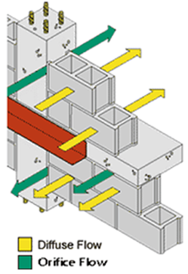
Figure 1. Air Leakage through a Building Enclosure
In traditional construction, infiltration occurs through gaps and cracks in the building envelope. Excess infiltration of cold air in the winter and hot humid air during the summer can create uncomfortable indoor environments and raise heating and cooling costs by 20% to 40%. Such unintentional infiltration is also a concern for an exterior chemical, biological, and radiological (CBR) release at some distance from a building, such as a large-scale attack. Decreasing infiltration improves comfort, saves energy, controls moisture, reduces indoor pollution, and makes forced ventilation necessary. Also, tight building construction in combination with building pressurization can be an effective CBR-protection strategy.
Commission Envelope Elements—the building commissioning process should include commissioning of the building envelope to insure that all performance requirements are being met. Commissioning of the building envelope can identify areas of concern related to air infiltration and leakage, moisture diffusion, surface condensation, and rain water entry—all issues that can negatively impact the building's energy performance and indoor environmental quality. Of particular importance is to begin commissioning of the building envelope during design when design modifications can be easily incorporated, rather than waiting until construction when remediation can cost significantly more.
While the LEED® Green Building Rating System requires buildings to undergo Fundamental Building Commissioning of systems to achieve certification, it merely recommends that some form of building envelope commissioning be incorporated. Lemieux and Totten have proposed a Building Envelope Commissioning process that could supplement the Fundamental Building Commissioning required for LEED® certification.
Incorporate Dedicated Ventilation and/or Exhaust Systems
Exposure of building occupants to potentially hazardous chemical, biological, and radiological (CBR) agents negatively impacts the indoor environment and can pose serious health threats. To help maintain superior indoor air quality and protect people's health, dedicated ventilation systems (aka. dedicated outdoor air systems [DOAS]) and dedicated exhaust systems can be installed. DOAS use separate air handlers to condition and deliver the minimum required constant volume of outdoor air. Be sure to protect all outdoor air intakes and locate away from all exhaust openings. For more information, see the Department of Health and Human Services Guidance for Protecting Building Environments from Airborne Chemical, Biological, or Radiological Attacks, May 2002 and Guidance for Filtration and Air-Cleaning Systems to Protect Building Environments from Airborne Chemical, Biological, or Radiological Attacks, April, 2003.
Use Dedicated HVAC Systems for Perimeter Zones
Provide dedicated HVAC systems to serve perimeter zones and maintain positive pressurization with respect to the building envelope. This strategy will help mitigate external and internal release of chemical, biological and radiological contamination.
Evaluate the HVAC System Controls

Figure 2. Ion Mobility Spectrometry (IMS) chemical detector designed for installation in HVAC Systems Courtesy Smiths Detection
Many HVAC systems incorporate energy management and control systems that can regulate air flows within a building on an emergency response basis. Consider utilizing the control system for this purpose. In some cases, simply shutting off the building's HVAC and exhaust systems might be the most effective means of avoiding introducing a CBR agent from outside the building. In other cases, pressurization and airflow control between zones within a building may be effective in minimizing the spread of a CBR agent released within the building. This strategy should include consideration of using pressure sensors inside and outside the building (and between zones) to measure pressure levels and control HVAC equipment to maintain pressure relationships.
If an HVAC control plan is pursued, building personnel should be trained to recognize a terrorist attack quickly and to know when to initiate the control measures. All procedures and training associated with the control of the HVAC system should be addressed in the building's emergency response plan.
Consider the Physical Security of HVAC Components
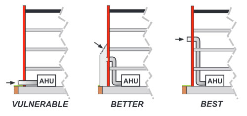
Figure 3. Protecting Outdoor Air Intakes Courtesy of Guidance for Protecting Building Environments From Airborne Chemical, Biological and Radiological Attacks, NIOSH
Outdoor Air Intakes—One of the most important steps that can be taken to protect a building's indoor environment from CBR attack is the security of outdoor air intakes. Introducing CBR agents into outdoor air intakes allows for the dispersion throughout the building via the HVAC system. Intakes at or below grade are most at risk due to their accessibility and because most CBR releases will be near the ground and remain there. Locate outdoor air intakes above the third floor of the building, and preferably at roof level whenever possible.
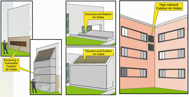
Figure 4. Vulnerable Outdoor Air Intakes Courtesy of Guidance for Protecting Building Environments From Airborne Chemical, Biological and Radiological Attacks, NIOSH
Rooftop HVAC Equipment—Roofs are similar to other entrances of a building and should be physically secured. Since HVAC equipment, including air handling units and their outside air intakes, are often located on rooftops and are susceptible to CBR attack, it is especially important to restrict access to the roof.

Figure 5. Example of Rooftop HVAC Equipment
Incorporate Higher Levels of Filtration
Filtration—This is an overall HVAC system issue, not only specific to the Building Envelope Design Guide. Please refer to BIPS 06 / FEMA 426 Reference Manual to Mitigate Potential Terrorist Attacks Against Buildings for a thorough discussion of filtration for CBR mitigation. Some consideration should also be given to the associated energy cost impact of installing the additional filtration equipment. Energy simulation and life cycle analysis tools can and should be used to assess the energy cost impacts.
Applications
The CBR Safety fundamentals previously described should be considered for and applied to the building envelope design and construction, and to HVAC systems interacting with the building envelope, for all buildings.
Related Issues
Balancing Security/Safety and Sustainability Objectives—Providing for sustainable designs that meet all facility requirements is often a challenge to the building design, construction and operation community. With limited resources it is not always feasible to provide for the most secure facility, the most architecturally expressive design, or energy efficient building envelope. From the concept stage through the development of construction documents, it is important that all project or design stakeholders work cooperatively to ensure a balanced design. Successful designs must consider all competing design objectives.
Integrated Design—Designers are moving away from the conventional building design approach that has historically resulted in little interaction between all parties involved in the project. There is a movement to embrace integrated building design, fostering communication amongst all parties that could be involved in the project, and facilitating working together from the start to coordinate and optimize the design of the site and the building.
Relevant Codes and Standards
Federal Mandates
- Executive Order 12977, "Interagency Security Committee"—Interagency Security Committee (ISC) Security Design Criteria-unites all Federal protective design requirements (For Official Use Only)
- Executive Order 12656, "Assignment of Emergency Preparedness Responsibilities"
Standards and Guidelines
- UFC 4-010-01 DoD Minimum Anti-Terrorism Standards for Buildings, U.S. Department of Defense
- Guidance for Protecting Building Environments from Airborne Chemical, Biological, or Radiological Attacks by the National Institute for Occupational Safety and Health (NIOSH)
- Guidance for Filtration and Air-Cleaning Systems to Protect Building Environments from Airborne Chemical, Biological, or Radiological Attacks by the National Institute for Occupational Safety and Health (NIOSH)
- PBS-P100 Facilities Standards for the Public Buildings Service, General Services Administration
- BIPS 06 / FEMA 426 Reference Manual to Mitigate Potential Terrorist Attacks Against Buildings by the Department of Homeland Security
- FEMA 427 Primer for Design of Commercial Buildings to Mitigate Terrorist Attacks
Additional Resources
Federal Agencies
- Centers for Disease Control and Prevention (CDC)
- Department of Homeland Security (DHS)
- Federal Emergency Management Agency (FEMA)
- Federal Facilities Council (FFC) Standing Committee on Cyber and Physical Security and Hazard Mitigation
Publications
- Building Ventilation and Pressurization as a Security Tool, Andy Persily, ASHRAE Journal, September 2004.
- Building Security Through Design: A Primer for Architects, Design Professionals, and their Clients, The American Institute of Architects, Washington DC, 2001
- Protection of Federal Office Buildings Against Terrorism, Committee on the Protection of Federal Facilities Against Terrorism, Building Research Board, National Research Council, Washington DC, National Academy Press, 1988.
- Uses of Risk Analysis to Achieve a Balanced Safety in Building Design and Operations, by Bruce D. McDowell and Andrew C. Lemer, Editors; Committee on Risk Appraisal in the Development of Facilities Design Criteria, National Research Council, Washington DC, National Academy Press, 1991.
Organizations
Cherry Point A/E Guide
This publication is issued to provide guidance to Architect-Engineer (A&E) firms performing services for the Officer in Charge NAVFAC Contracts, Marine Corps Air Station, Cherry Point, North Carolina. It is essential that all A&E personnel and associates responsible for preparing plans, specifications, cost estimates, studies or other services, follow all procedures and instructions outlined herein. All A&E contracts issued by OIC NAVFAC Contracts, MCAS, Cherry Point, NC reference this guide as part of the contract.
Child Care
Overview
Within This Page
The Child Care space types, described herein, are the facilities required for child care services permitted within federal facilities. The intention of high quality federal child care is to allow employees to respond to their dual work and family responsibilities effectively to the benefit of both families and the government as employer. A licensed child care center is a facility, other than a private residence, approved and licensed by a state or other applicable local authority where a person, other than a relative or guardian, is compensated to provide care and supervision for 4 or more children under 7 years of age for less than 24 hours a day. A "small" center is one which is licensed for less than 60 children, while a "large" one is licensed for more than 94 children. Child Care space types include additional support and space sub-types, including toilets, food preparation and service, office space, and meeting space, as well as security features required in compliance with codes and regulations.

Space Attributes
Child Care spaces should be secure environments that provide a variety of learning experiences and meet the physical needs of the children. See WBDG Child Development Centers for more information on the unique attributes of spaces designed for child development and care. Typical features of Child Care space types include the list of applicable design objectives elements as outlined below. For a complete list and definitions of the design objectives within the context of whole building design, click on the titles below.
Accessible
- Child care center design must comply with the Americans with Disabilities Act (ADA). The design must accommodate children and adults with disabilities. The site, as well as the building access to and within the child care spaces, shall comply with the current publication of the Uniform Federal Accessibility Standards (UFAS), the final rules of the Americans with Disabilities Act Accessibility Guidelines (ADAAG), and local accessibility codes, whichever is most stringent.
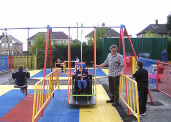
Accessible swing for wheelchair users. Photo Credit: kaboom.org
Functional / Operational
Classrooms are the architecturally defined areas that contain each group of children. Classrooms may be separated by full partitions or by partial barriers that also allow controlled visual or acoustical connections to other groups.
Design spaces with a sensitivity to children's scale, including how they will use the space, what they will see, and what kind of experience they will have.
Classroom equipment and durable goods including cots and cribs, chairs and other seating devices, furniture, play equipment, academic equipment, presentation equipment, audiovisual equipment, computer equipment, food service, and hygiene equipment must be provided. Provide durable and cost-effective materials and details. This is vital when the designer considers the intensity of use that a center receives. Particular sensitivity should be paid to the life-cycle cost of materials.
Outdoor spaces may include play yard space, including fencing, canopy, sidewalk, ground cover, drainage, shade devices, play structures, and vegetation planting. See WBDG Playground Design and Equipment for more information.
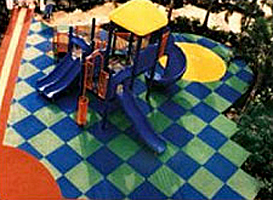
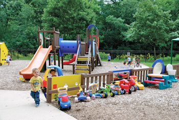
Playground surfaced with poured-in-place rubber and rubber mats.
This playground offers a mix of sand play area, hard surface zone, and gross motor skills area.
Occupancy: Occupancy Group Classification is Educational Occupancy E as sub-occupancy with Business B2 Building Occupancy, with sprinklered construction. See also WBDG Secure / Safe—Fire Protection.
Productive
Office space in Child Care space types should be equipped with infrastructure to support telephone and data communication systems including space, power, and conduit and telephone and data communication equipment.
Consider providing on-site food service areas directly serving the daycare population and on-site laundry services and water services including hot water and water conditioners.
Secure / Safe
Whenever possible, design the space to prevent direct access to the child care area. Instead, create a secure main entrance which will be separated from the doors to individual child care rooms and spaces so that a person entering may need to go down a hallway or around a corner to get to a child care entrance.
Security equipment for Child Care space types may include access control, intrusion detection, and alarm systems. See also WBDG Secure / Safe—Security for Building Occupants and Assets.
Additional elevators and exit stairways may be required for Child Care spaces located on the 2nd level of buildings.
Ensure that there is adequate exterior lighting to allow safe exterior circulation and site security.
Sustainable
Provide ample natural light in all spaces where children will spend time, especially the classrooms.
Minimize energy use. Also consider placement of mechanical equipment to ensure energy efficiency as well as acoustic comfort and control.
Equipment, furnishings, and finishes must be non-toxic and not contain asbestos, lead, or other VOCs.
Equipment, furnishings and finishes should be cleaned and maintained using sustainable cleaning or improved maintenance practices.
Good indoor air quality must be provided.
See also WBDG Secure / Safe—Occupant Safety and Health
Example Program
The following building program is representative of Child Care center space types and is based on the ratios prescribed in the PBS-140 Child Care Center Design Guide. The center described below included provisions for 86 children.
CHILD CARE
| Description Tenant Occupiable Areas |
Qty. | SF Each | Space Req'd. | Sum Actual SF | Tenant Usable Factor | Tenant USF |
|---|---|---|---|---|---|---|
| Staff and Parent Areas | 1,140 | |||||
| Public Area | ||||||
| Vestibule | 1 | 60 | 60 | |||
| Reception | 1 | 100 | 100 | |||
| Staff Area | ||||||
| Director's Office | 1 | 150 | 150 | |||
| Assistant's Workstation | 1 | 80 | 80 | |||
| Sick Bay | 1 | 80 | 80 | |||
| Staff Lounge/Work | 1 | 200 | 200 | |||
| Parent/Staff Conference | 2 | 100 | 200 | |||
| Adult Toilet | 2 | 60 | 120 | |||
| Central Storage | 1 | 150 | 150 | |||
| Service Areas | 560 | |||||
| Laundry | 1 | 100 | 100 | |||
| Warming/Central Kitchen | 1 | 300 | 300 | |||
| Janitor's Closet | 1 | 80 | 80 | |||
| Telephone Closet | 1 | 80 | 80 | |||
| Common Spaces | 1,000 | |||||
| Multiple Purpose Space | 1 | 800 | 800 | |||
| Play Yard Storage | 1 | 200 | 200 | |||
| Classrooms | 7,200 | |||||
| Infant Classroom (8) | 1 | 900 | 900 | |||
| Younger Toddler Classroom (12) | 2 | 1,060 | 2,120 | |||
| Younger Toddler Restroom | 2 | 40 | 80 | |||
| Older Toddler Classroom (14) | 1 | 1,060 | 1,060 | |||
| Older Toddler Restroom | 1 | 40 | 40 | |||
| Preschool Classroom (20) | 1 | 1,440 | 1,440 | |||
| Preschool Restroom | 1 | 60 | 60 | |||
| After School Classroom (20) | 1 | 1,440 | 1,440 | |||
| After School Restroom | 1 | 60 | 60 | |||
| Outside Areas | ||||||
| Staff Parking | 18 | 300 | 5,400 | |||
| Parent Drop Off/Parking | 10 | 300 | 3,000 | |||
| Entrance Porch | 1 | 400 | 400 | |||
| Play Yard Porches | 4 | 400 | 1,600 | |||
| Play Yards | 4 | 1,500 | 6,000 | |||
| Tenant Suite | 9,900 | 9,900 | 1.17 | 11,612 | ||
| Subtotal Tenant Usable Areas | 11,612 |
Example Plans
The following diagram is representative of typical tenant plans.
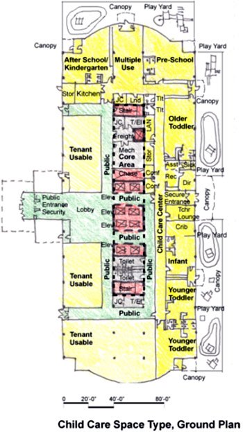
Example Construction Criteria
For GSA, the unit costs for child care space types are based on the construction quality and design features in the following table . This information is based on GSA's benchmark interpretation and could be different for other owners.
Relevant Codes and Standards
The following agencies and organizations have developed codes and standards affecting the design of child care centers. Note that the codes and standards are minimum requirements. Architects, engineers, and consultants should consider exceeding the applicable requirements whenever possible.
- ADA Standards
- Energy Policy Act of 2005 (EPACT)
- Executive Order 13101, "Greening the Government Through Waste Prevention, Recycling, and Federal Acquisition," September 14, 1998.
- Executive Order 13148, "Greening the Government through Leadership in Environmental Management," June 1999.
- GSA PBS-140 Child Care Center Design Guide
- GSA PBS-P100 Facilities Standards for the Public Buildings Service
- Interagency Security Committee (ISC) Security Design Criteria—Contains specifications pertaining to window protection in child care centers located in GSA controlled facilities. (For Official Use Only)
- ICC IBC International Building Code
- U.S. Access Board, Play Area Guidelines
Additional Resources
Organizations and Associations
- Building Child Care in California—This project exists to provide a centralized clearinghouse of information and services designed to improve child care providers' access to financial resources for facilities development projects in California.
- National Resource Center for Health and Safety in Child Care and Early Education—The NRC's primary mission is to promote health and safety in out-of-home child care settings throughout the nation.
Publications
- Architectural Graphic Standards, 12th Edition by American Institute of Architects, Dennis J. Hall. New York, NY: John Wiley & Sons, Inc., 2016.
- Children, Youth and Environments, CYE is a refereed journal and multidisciplinary, international network dedicated to improving the lives of young people. The journal targets researchers, policy makers, and professionals and is guided by a distinguished Editorial Advisory Board.
Child Development Center Model RFP
NOTE: Only PART 2 GENERAL REQUIREMENTS have been updated this quarter.
FOR ALL DOCUMENTS AND ATTACHMENTS–Download the complete set zipped file. You may also add your company name, work order number, and project name to the documents in a customizable set.
FOR INDIVIDUAL DOCUMENTS–Find the document in the list below and download the appropriate format.
Questions, comments, suggestions and recommended changes for the NDBM are welcome and should be submitted as a Criteria Change Request. To submit a Criteria Change Request, click on the CCR link next to the appropriate document below.
In PART 2 - GENERAL REQUIREMENTS, the indicates the file is an attachment to the UFGS.
| Title | Date | View | CCR |
|---|---|---|---|
| CHILD DEVELOPMENT CENTER COMPLETE SET | 09-15-2024 | View/Download | |
| PART 2 - GENERAL REQUIREMENTS | |||
| 1.0 Table of Contents (RFP Parts 2-6) | 09-15-2024 | View/Download | CCR |
| UFGS 01 14 00 Work Restrictions | 11-01-2022 | View/Download | View/Download | CCR |
| UFGS 01 20 00 Price and Payment Procedures | 11-01-2020 | View/Download | View/Download | CCR |
| UFGS 01 30 00 Administrative Requirements | 11-01-2020 | View/Download | View/Download | CCR |
| UFGS 01 31 19.05 20 Concept Design Workshop (CDW) | 02-01-2021 | View/Download | View/Download | CCR |
| UFGS 01 31 23.13 20 Electronic Construction and Facility Support Contract Management System (eCMS) | 08-01-2023 | View/Download | View/Download | CCR |
| UFGS 01 32 17.00 20 Cost-Loaded Network Analysis Schedules (NAS) Contractor Baseline Project Schedule Review Checklist (PDF) Contractor Baseline Project Schedule General Commissioning / HVAC Review Checklist (PDF) Contractor Monthly Update Schedule Review Checklist (PDF) | 11-01-2023 | View/Download | View/Download | CCR |
| UFGS 01 33 00.05 20 Construction Submittal Procedures | 05-01-2014 | View/Download | View/Download | CCR |
| UFGS 01 33 10.05 20 Design Submittal Procedures | 05-01-2017 | View/Download | View/Download | CCR |
| UFGS 01 33 29 Sustainability Requirements and Reporting | 02-01-2021 | View/Download | View/Download | CCR |
| UFGS 01 35 13 Special Project Procedures | 11-01-2020 | View/Download | View/Download | CCR |
| UFGS 01 35 26 Governmental Safety Requirements Contractor Safety Self-Evaluation Checklist (PDF) | 05-01-2024 | View/Download | View/Download | CCR |
| UFGS 01 45 00 Quality Control Contractor Production Report (PDF) Schedule of Fire Protection System Inspections by the FPQC (DOCX) | 08-01-2023 | View/Download | View/Download | CCR |
| UFGS 01 45 35 Special Inspections Schedule of Special Inspections (DOCX) Statement of Special Inspections (XLSX) | 11-01-2020 | View/Download | View/Download | CCR |
| UFGS 01 50 00 Temporary Construction Facilities and Controls Temp Signs — English (PDF) Temp Signs — Metric (PDF) Contractor Computer Cybersecurity Compliance Statement (DOCX) Contractor Temporary Network Cybersecurity Compliance Statement (DOCX) | 11-01-2020 | View/Download | View/Download | CCR |
| UFGS 01 57 19 Temporary Environmental Controls Contractor Hazardous Material Inventory Log (PDF) Hazardous Waste Minimization and Disposal Guide (PDF) Spill Reporting Contact Numbers (PDF) Bangor Formset (ZIP) Bremerton Formset (ZIP) Everett Formset (ZIP) Indian Island Formset (ZIP) Keyport Formset (ZIP) Whidbey Formset (ZIP) | 08-01-2022 | View/Download | View/Download | CCR |
| UFGS 01 74 19 Construction Waste Management and Disposal | 02-01-2019 | View/Download | View/Download | CCR |
| UFGS 01 78 00 Closeout Submittals | 05-01-2019 | View/Download | View/Download | CCR |
| UFGS 01 78 23 Operation & Maintenance Data O&M Manual Template (DOCX) | 05-01-2023 | View/Download | View/Download | CCR |
| UFGS 01 78 24.00 20 Facility Data Workbook (FDW) eOMSI Facility Data Workbook (FDW) (XLSM) | 05-01-2023 | View/Download | View/Download | CCR |
| UFGS 01 91 00.15 Building Commissioning Pre-Functional Checklists (ZIP) Building Envelope Inspection (ZIP) Functional Performance Test Checklists (ZIP) Integrated Systems Test Checklists (ZIP) | 05-01-2023 | View/Download | View/Download | CCR |
| UFGS 01 91 19 Building Enclosure Commissioning Appendix A — Air Leakage Test Form (DOCX) Appendix B — Air Leakage Test Results Form (DOCX) Appendix C — Test Agency Qualifications Sheet (DOCX) Pressure Test Data Analysis (XLSX) | 05-01-2023 | View/Download | View/Download | CCR |
| PART 3 - PROJECT PROGRAM | |||
| 1.0 Project Description | 09-01-2022 | View/Download | CCR |
| 2.0 Project Objectives | 06-01-2023 | View/Download | CCR |
| 3.0 Site Analysis | 09-01-2022 | View/Download | CCR |
| 4.0 Building Requirement | 09-01-2022 | View/Download | CCR |
| 5.0 Room Requirements | 09-01-2022 | View/Download | CCR |
| 6.0 Engineering System Requirements | CCR | ||
| – ESR-A10 Foundations | 02-01-2018 | View/Download | CCR |
| – ESR-A20 Basement Construction | 02-01-2018 | View/Download | CCR |
| – ESR-B10 Superstructure | 09-01-2022 | View/Download | CCR |
| – ESR-B20 Exterior Closure | 09-01-2022 | View/Download | CCR |
| – ESR-B30 Roofing | 06-01-2023 | View/Download | CCR |
| – ESR-C10 Interior Construction | 09-01-2022 | View/Download | CCR |
| – ESR-C20 Stairs | 02-01-2018 | View/Download | CCR |
| – ESR-C30 Interior Finishes | 09-01-2022 | View/Download | CCR |
| – ESR-D10 Conveying | 02-01-2018 | View/Download | CCR |
| – ESR-D20 Plumbing | 09-01-2022 | View/Download | CCR |
| – ESR-D30 HVAC | 09-01-2022 | View/Download | CCR |
| – ESR-D40 Fire Protection | 02-01-2018 | View/Download | CCR |
| – ESR-D50 Electrical | 06-01-2023 | View/Download | CCR |
| – ESR-E10 Equipment | 09-01-2022 | View/Download | CCR |
| – ESR-E20 Furnishings | 09-01-2022 | View/Download | CCR |
| – ESR-F10 Special Construction | 02-01-2018 | View/Download | CCR |
| – ESR-F20 Selective Building Demolition | 09-01-2022 | View/Download | CCR |
| – ESR-G10 Site Preparation | 09-01-2022 | View/Download | CCR |
| – ESR-G20 Site Improvements | 09-01-2022 | View/Download | CCR |
| – ESR-G30 Site Civil/Mechanical Utilities | 09-01-2022 | View/Download | CCR |
| – ESR-G40 Site Electrical Utilities | 09-01-2022 | View/Download | CCR |
| PART FOUR - PERFORMANCE TECHNICAL SPECIFICATIONS | |||
| PTS-A10 Foundations | 12-15-2018 | View/Download | CCR |
| PTS-A20 Basement Construction | 12-15-2018 | View/Download | CCR |
| PTS-B10 Superstructure | 12-15-2018 | View/Download | CCR |
| PTS-B20 Exterior Enclosure | 06-01-2023 | View/Download | CCR |
| PTS-B30 Roofing | 06-01-2023 | View/Download | CCR |
| PTS-B30 Appendix A Forms | 09-01-2022 | View/Download | CCR |
| PTS-C10 Interior Construction | 09-01-2022 | View/Download | CCR |
| PTS-C20 Stairs | 09-01-2022 | View/Download | CCR |
| PTS-C30 Interior Finishes | 09-01-2022 | View/Download | CCR |
| PTS-D10 Conveying | 06-01-2023 | View/Download | CCR |
| PTS-D20 Plumbing | 12-15-2018 | View/Download | CCR |
| PTS-D30 HVAC | 06-01-2023 | View/Download | CCR |
| PTS-D40 Fire Protection | 12-15-2018 | View/Download | CCR |
| PTS-D50 Electrical | 09-01-2022 | View/Download | CCR |
| PTS-E10 Equipment | 09-01-2022 | View/Download | CCR |
| PTS-E20 Furnishings | 09-01-2022 | View/Download | CCR |
| PTS-F10 Special Construction | 09-01-2022 | View/Download | CCR |
| PTS-F20 Selective Building Demolition | 09-01-2022 | View/Download | CCR |
| PTS-G10 Site Preparation | 09-01-2022 | View/Download | CCR |
| PTS-G20 Site Improvements | 09-01-2022 | View/Download | CCR |
| PTS-G30 Site Civil/Mechanical Utilities | 09-01-2022 | View/Download | CCR |
| PTS-G40 Site Electrical Utilities | 09-01-2022 | View/Download | CCR |
| PTS-Z10 General Performance Technical Specification | 06-01-2023 | View/Download | CCR |
Child Development Centers
Overview
Within This Page
While their parents work, seven out of ten American children under the age of six participate in some form of care outside the home. Because many of them spend up to 12,500 hours in a child development center—most of their waking hours—the facility must be designed to provide safe, nurturing, and stimulating environments essential for the healthy development of our children.
WBDG accepts the majority view that all child development centers should stress quality care, and child growth and development. To this end, all child development centers are encouraged to provide well-illuminated, active and passive activity areas that accommodate a range of play and organized learning as well as serve the needs of adult staff and parents, and facilitate staff-child relationship building.
There are nationally recognized accreditation agencies, such as the National Association for the Education of Young Children (NAEYC), that identify requirements for quality child development programs and facility conditions, including safety, sanitation, natural daylight, and classroom size.
Building Attributes
While child development centers can take many forms—they can be stand-alone or part of some larger structure; they can be urban or rural; they can be large or small.
A. Types of Spaces
Child Development Centers will contain a variety of space types depending on the hours they are used, the age of the children attending, the number of children attending, and the setting for the center. Fundamental space types may include, but are not limited to, the following:

Hallway with reading niche at child development center in Des Moines, Iowa. Photo Credit: Architects Wells, Kastner, Schipper
- Child-friendly classrooms
- Meeting or community space for children and adults
- Child-friendly and adult restrooms
- Outdoor and indoor play areas
- Office space for staff
- Meeting space for adults
- Clinic
- Food service space
- Storage space
- See also WBDG Space TypeChild Care
All child development centers should seek to:
B. Be Homelike
Like a home, a quality child development center is a place where children can:
- Relax and be themselves
- Have ample natural light in all spaces were children will spend time, especially the classrooms
- Have a sense of arrival and welcome upon entering the center for both children and parents
- Use indirect lighting as main ambient lighting to avoid a "commercial" flavor
- Feel and be safe and secure
- Find different places for different kinds of learning
- Work and play using different furnishings and varied lighting
- Avoid institutional, unnatural finishes and textures. Use natural finishes to the extent possible, emphasizing a "hand-made" appearance
- Have no sharp edges: ½" bull-nose on all exterior corners at child-level gypsum and trim typical. Integral bull nose corner beads are recommended
- See also WBDG Provide Comfortable Environments
C. Be Child-Sized
Preferably, facilities designed for children should have:
- Child-sized furniture appropriate to the specific age group served
- Ceiling heights should be varied, low enough for intimacy, and high enough to avoid a monotonous spatial experience
- Windows at children's level
- Doors, sinks, toilets, and water fountains that are "child friendly" and mounted at appropriate heights
- See also WBDG Functional / Operational
D. Encourage Autonomy
Child development centers should be designed to allow children to:
- Independently address bodily needs such as hunger, thirst, using the toilet, and sleep
- Set their own pace
- Choose activities and toys
- Choose their own friends and companions - or be alone
- Be active or still
- Create three-dimensional projects that are protected from destruction by everyday traffic through classroom space
- See also WBDG Promote Health and Well-Being
E. Invite Self-Expression
Such facilities are characterized by:
- Restraint in color and furnishings (e.g., neutral tones for backgrounds and ceilings, with warm colors for accents)
- Space for children's art, located at the children's eye level together with a well-thought out and safe way of hanging art and displaying three-dimensional projects
- Space for objects that children bring to share or that have special meaning
- Changing displays more than permanent graphics
F. Provide Space, Indoor and Outdoor Physical Activities
Child development centers should have playground and multi-purpose play space for inclement weather. These areas should allow:
- Running
- Playing ball
- Climbing, swinging, sliding, and balancing
- Storage of play items such as tricycles
- Access to nearby toilets
- Controlled access for maintenance


Playground areas at a child development center in Honolulu, Hawaii allow children to interact with their peers and explore their surroundings. Photo Credit: Landscape & Playground Designers Moore Iacofano Goltsman (MIG)
G. Have Outdoor and Indoor Spaces for Nature
When possible, they should contain places to:
- Dig in dirt or sand
- Play with water
- Grow seeds, flowers, and vegetables
- Investigate animal life
- Collect rocks, leaves, or other specimens
- Contain a variety and scale of natural elements such as trees, flowers, and shrubs
- Have quiet time, away from the "crowd" while still being able to be supervised
- Places for large motor activities such as climbing and riding wheeled toys
- Storage shed(s) for storage of outdoor equipment
- Have a (typically) 6'–0" fence completely surrounding the play area
H. Be Structured, Yet Flexible
This means that different spaces in a facility:
- Can be recognized by children
- Are for quiet and active play
- Can be rearranged by children for their own activities
- Contain adequate storage facilities to avoid a chaotic impression
- See also WBDG Beyond Accessibility to Universal Design
I. Include Appropriate Space for Parents and Teachers
This includes places to:
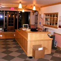
Staff can monitor and control access to the child development center from desks positioned at the entry such as the one shown in the photo. World Bank, Washington, DC
- Think and plan
- Meet and communicate
- Host visitors
- Store equipment
- Keep record
- Come together and celebrate as a community
J. Be Safe, Secure, and Healthy
This includes provisions and strategies to ensure that:
- Children are not abused by adults in the center
- People / personnel do not have uncontrolled access
- There are adequate washing facilities
- Finishes are easily cleaned
- Attention is paid to good indoor air quality as well as to the use of daylighting, non-toxic building materials and improved maintenance practices
- Equipment, furnishings, and finishes do not contain asbestos or lead
- See also WBDG Ensure Occupant Safety and Health
Relevant Codes and Standards
As the number of child development centers increases, more and more agencies, states, and municipalities are requiring that child development centers within their jurisdictions meet minimum facility and operating standards. However, in most states the facilities requirements are limited to relatively few and minimal health and safety issues such as the adequacy of bathrooms, egress, and lighting. The most comprehensive facilities standards available at present, sometimes cited in state and municipal codes, are those promulgated by federal agencies. Among the organizations that have led the way toward the definition of comprehensive child development centers criteria are the U.S. General Services Administration, Department of Health and Human Services, and the Department of Defense.
Federal Mandates and Criteria
- ADA Accessibility Guidelines for Building Elements Designed for Children's Use
- ADA Guide: Accessibility Guidelines for Play Areas
- Executive Order 13693, "Planning for Federal Sustainability in the Next Decade"
- UFC 3-210-04 Children's Outdoor Play Area
- UFC 4-740-14 Design: Child Development Centers (USACE and Air Force Only)
- FC 4-740-14N Navy and Marine Corps Child Development Centers
- UFGS 11 68 13 Playground Equipment
- UFGS 32 18 16.13 Playground Protective Surfacing
- VHA PG-18-9: Space Planning Criteria, Chapter 420 Childcare / Development Center
Standards and Guidelines
- Army TM 5-663 Child Development Center Play Area Inspection and Maintenance Program
- ASTM F355 Standard Test Method for Impact Attenuation of Playing Surface Systems, Other Protective Sport Systems, and Materials Used for Athletics, Recreation and Play
- Consumer Product Safety Commission, Public Playground Safety Handbook
- EPA Comprehensive Procurement Guidelines for Park and Recreation Products EPA
- Head Start Center Design Guide: A guide for building a Head Start Faciity , Department of Health and Human Services
- PBS-140 Child Care Center Design Guide, General Services Administration
- Property Manager's Child Care Resource Book , General Services Administration
Additional Resources
Organizations
- GSA Child Office of Child Care — The primary mission of GSA's Child Care Operations Center of Expertise is to ensure that federal families receive high quality care for their young children in child care centers located in GSA managed space.
- National Association for the Education of Young Children (NAEYC) — An advocacy organization for preschool care and education
- National Child Care Association (NCCA) — A trade association for private, for-profit child-care facility operators
- National Children's Facilities Network — A coalition of nonprofit financial and technical assistance intermediaries involved in planning, developing, and financing facilities for low-income child care and Head Start programs
Publications
- BIPS 07 / FEMA 428 Primer to Design Safe School Projects in Case of Terrorist Attacks and School Shootings
- Caring for Our Children, National Health and Safety Performance Standards: Guidelines for Out-of-Home Child Care Programs, 3rd Edition American Academy of Pediatrics, American Public Health Association, National Resource Center for Health and Safety in Child Care and Early Education. 2011.
- Child Care Design Guide by Anita Rui Olds. New York, NY: McGraw-Hill, 2000.
- Creating Environments for Learning: Birth to Age Eight, 3rd Edition by Julie Bullard. Pearson Education, 2017.
- Greening Early Childhood Centers by Mike Lindstrom and Amy Gillman. Local Initiatives Support Corporation/Connecticut Children's Investment Partnership, 2010.
- Play and Playscapes by Joe Frost. Albany, New York: Delmar Publications, Inc., 1992.
Other
- Infant/Toddler Environment Rating Scales, by Thelma Harms, Debby Cryer, and Richard M. Clifford. Frank Porter Graham Child Development Institute of the University of North Carolina at Chapel Hill. Revised Edition.
Christ Hospital Joint and Spine Center
General Information
Building Name: The Christ Hospital Joint and Spine Center Building Location: 2139 Auburn Ave, Cincinnati, Ohio, United States Project Size: 365,000 sf / 33.910m2 Building Type(s): Operating rooms, in-patient rooms, offices Project Type: New Construction/Expansion Delivery Method: CM at Risk Total Building Costs:
Civil Engineer Squadron Administration Facility
General Information
- Standard Design – AF Civil Engineer Squadron Administration Facility
- Civil Engineer Squadron Administration Facility Programming Worksheet
Drawings
| Title | View |
|---|---|
| Civil Engineer Squadron Administration Facility | View/Download |
Civil Engineer Squadron Design Guide (AMC)
This guide provides the basic criteria to organize, evaluate, plan, program, and design Air Mobility Command (AMC) civil engineer (CE) facilities. The information presented is intended to make commanders and their staffs aware of important design considerations and to aid them in project development. These facilities should provide an atmosphere in which customers feel comfortable while receiving quality assistance. This guide is for use by commanders, Headquarters AMC staff, design architects and engineers, and others involved in CE facilities design and construction. Use this guide to supplement other Air Force (AF) and Department of Defense (DoD) policies and instructions.
Civil Engineer Squadron Explosive Ordinance Disposal Facility
General Information
- Standard Design – Civil Engineer Squadron Explosive Ordinance Disposal Facility
- Civil Engineer Squadron Administration Facility Programming Worksheet
Drawings
| Title | View |
|---|---|
| Civil Engineer Squadron Explosive Ordinance Disposal Facility | View/Download |
Civil Engineer Squadron Facility Maintenance Building
General Information
- Standard Design –Civil Engineer Squadron Facility Maintenance Building
- Civil Engineer Squadron Facility Maintenance Building Programming Worksheet
Drawings
| Title | View |
|---|---|
| Civil Engineer Squadron Facility Maintenance Building | View/Download |
Civil Engineer Squadron Pest Management
General Information
- Standard Design –Civil Engineer Squadron Pest Management
- Civil Engineer Squadron Pest Management Programming Worksheet
Drawings
| Title | View |
|---|---|
| Civil Engineer Squadron Pest Management | View/Download |
Civil Engineer Squadron Shops/Warehouse Building
General Information
- Standard Design – Civil Engineer Squadron Shops/Warehouse Building
- Civil Engineer Squadron Shops/Warehouse Building Programming Worksheet
Drawings
| Title | View |
|---|---|
| Civil Engineer Squadron Shops/Warehouse Building | View/Download |
Civil Engineering
INTRODUCTION
Within This Page
Civil engineering is not all about fancy buildings – it is about maintaining vital infrastructure. When people think of famous civil engineers from the past, they think of Isambard Kingdom Brunel and Joseph Bazalgette, the great engineer of the Victorian age who saved London from cholera by constructing new sewers.
Today, civil engineering is often associated with the world's most jaw-dropping structures, such as Sydney Opera House, the Shard and China's Jiaozhou Bay Bridge. But civil engineering is also about maintaining and adapting the infrastructure that people depend on every day - roads, railways and bridges, energy and water supply, waste networks, and flood defenses. Civil engineers have to keep this infrastructure running effectively and adapt it to meet challenges, such as population growth, climate change, and natural disasters.
They must also find ways to deliver the infrastructure needed when there is little money to pay for it. Put simply, civil engineers have to come up with solutions to complex problems and implement them; they literally shape the world people live in.
DESCRIPTION
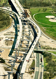
Civil engineers shape the world
There are two types of civil engineering roles: consultants who focus on design work and generally spend more time in the office or working with clients, and contractors who are more involved with keeping an eye on the physical construction and are usually based on-site. Both are challenging environments, and all civil engineers are required to be innovative and logical individuals. Other essential attributes civil engineers need include: creativity, versatility, a problem-solving mind, and the ability to understand the bigger picture and to collaborate with a number of other professionals.
Civil engineers design, build, supervise, operate, and maintain construction projects and systems in the public and private sector, including roads, buildings, airports, tunnels, dams, bridges, and systems for water supply and sewage treatment. Many civil engineers work in design, construction, research, and education.
The duties of a civil engineer may typically include any or all of the following:
- Analyze long-range plans; survey reports, maps, and other data in order to plan projects.
- Consider construction costs, government regulations, potential environmental hazards, and other factors in planning the stages of, and risk analysis for a project.
- Compile and submit permit applications to local, state, and federal agencies, verifying that projects comply with various regulations.
- Test building materials, such as concrete or asphalt for use in particular projects.
- Provide cost estimates for materials, equipment, or labor to determine a project's economic feasibility.
- Use design software to plan and design transportation systems, hydraulic systems, and structures in line with industry and government standards.
- Perform or oversee surveying operations in order to establish reference points, grades, and elevations to guide construction or design.
- Present their findings to the public on topics such as bid proposals, environmental impact statements, or descriptions of projects.
- Manage the repair, maintenance, and replacement of public and private infrastructure.
Civil engineers inspect projects to insure regulatory compliance. In addition, they are tasked with ensuring that safe work practices are followed at construction sites.
Many civil engineers hold supervisory or administrative positions ranging from supervisor of a construction site to city engineer, public works director, or city manager. Others work in design, construction, research, and education. Civil engineers work with other professionals on projects and may be assisted by civil engineering technicians.
Civil engineers design, build, and maintain the foundation for modern society – from roads and bridges, drinking water and energy systems, to seaports and airports, and the infrastructure for a cleaner environment, to name just a few. Civil engineering touches people throughout their day. Think of a civil engineer when:
- Turning on the tap to take a shower or drink clean water.
- Flicking on the lights and opening the refrigerator.
- Driving to work on roads and bridges through synchronized traffic lights.
- Taking mass transit or taking a flight for a vacation.

Civil Engineers make mass transit feasible.
Entrusted by society to create a sustainable world and enhance the global quality of life, civil engineers serve competently, collaboratively, and ethically as master planners, designers, constructors, and operators of society's economic and social engine - the built environment. They are stewards of the natural environment and its resources; innovators and integrators of ideas and technology across the public, private, and academic sectors; managers of risk and uncertainty caused by natural events, accidents, and other threats. They also serve as leaders in discussions and decisions shaping public environmental and infrastructure policy.
Every person, family, and business needs infrastructure to thrive - from the roads travelled to work, to the pipes that deliver clean drinking water, to the inland waterways, and rails that move goods from coast to coast. The American Society of Civil Engineers' 2013 Report Card for America's Infrastructure depicts the condition and performance of the nation's infrastructure in the familiar form of a school report card-assigning letter grades based on the physical condition and needed investments for improvement. The report card is available for public viewing at ASCE.org.
EMERGING ISSUES

Sustainability is an issue that The American Society of Civil Engineers (ASCE) defines as a set of economic, environmental, and social conditions in which all of society has the capacity and opportunity to maintain and improve its quality of life indefinitely without degrading the quantity, quality, or the availability of economic, environmental, and social resources. Sustainable development is the application of these resources to enhance the safety, welfare, and quality of life for all of society. Civil engineers shall be committed to the following ASCE Principles of Sustainable Development.
- Principle 1- Do the Right Project. A proposed project's economic, environmental, and social effects on each of the communities served and affected must be assessed and understood by all stakeholders before there is a decision to proceed with a project. Consider non-structural as well as structural (built) solutions to the needs being addressed: and
- Principle 2 - Do the Project Right. The civil engineer shall actively engage stakeholders and secure public understanding and acceptance of a project’s economic, environmental, and social costs and benefits. To move toward conditions of sustainability, engineers must design and deliver projects that address sustainability holistically (from concept to demolition or reuse) rather than adding a variety of "green" features onto a conventional project.
ASCE supports the following steps to achieve a sustainable project:
- Perform Life-Cycle Assessment from Planning to Reuse. Project participants should use rigorous life cycle methodologies that quantify the economic, environmental, and social effects of the project.
- Use Resources Wisely - Minimize Use of Non Renewable Resources. Sustainable development shall include progressive reductions in resource use for a given level of service and resiliency. The feasibility of restoration, or return of depleted resources, shall be evaluated by the civil engineer.
- Plan for Resiliency. Sustainability requires planning for the impact natural and man-made disasters and changing conditions can have on economic, environmental, and social resources.
- Validate Application of Principles. Civil engineers must guide project development and validate the application of these principles by using metrics and rating tools such as the EnvisionTM Rating System for sustainable infrastructure.
ASCE recognizes the leadership role of engineers in sustainable development and their responsibility to provide effective and innovative solutions in addressing the challenges of sustainability. The ASCE Code of Ethics requires civil engineers to strive to comply with the principles of sustainable development in the performance of their professional duties. ASCE works on a global scale to promote public recognition and understanding of the needs and opportunities for sustainable development.
Environmental, economic, social, and technological development must be seen as interdependent and complementary concepts, where economic competitiveness and ecological sustainability are complementary aspects of the common goal of improving the quality of life. Engineers have a leading role in planning, designing, building, and ensuring a sustainable future. Engineers provide the bridge between science and society. In this role, engineers must actively promote and participate in multidisciplinary teams with other professionals, such as ecologists, economists, and sociologists, and work with the communities served and affected to effectively address the issues and challenges of sustainable development.
RELEVANT CODES AND STANDARDS
American Association of State Highway and Transportation Officials (AASHTO) - A Policy on Geometric Design of Highways and Streets
Department of Defense
- Unified Facilities Criteria (UFC)
- UFC 1-300-09N Navy and Marine Corps Design Procedures
- UFC 3-201-01 Civil Engineering
- UFC 3-210-10 Low Impact Development
- UFC 3-220-05 Dewatering and Groundwater Control
- UFC 3-230-01 Water Storage, Distribution, and Transmission
- UFC 3-230-03 Water Treatment
- UFC 3-240-01 Wastewater Collection
- UFC 3-240-02 Domestic Wastewater Treatment
- UFC 3-250-01 Pavement Design for Roads and Parking Areas
- UFC 3-250-03 Standard Practice Manual for Flexible Pavements
- UFC 3-250-04 Standard Practice for Concrete Pavements
- UFC 3-250-08FA Standard Practice for Sealing Joints and Cracks in Rigid and Flexible Pavements
- UFC 3-250-09FA Aggregate Surfaced Roads and Airfields Areas
- UFC 3-250-11 Soil Stabilization for Pavements
- UFC 3-260-01 Airfield and Heliport Planning and Design
- UFC 3-260-02 Pavement Design for Airfields
- UFC 3-260-03 Airfield Pavement Evaluation
International Code Council
Department of Justice
Department of Transportation
Additional Resources
WBDG
ORGANIZATIONS AND ASSOCIATIONS
- American National Standards Institute
- American Society for Testing and Materials
- The American Society of Civil Engineers (ASCE)
- American Water Works Association
- Environmental Protection Agency
- Great Lakes – Upper Mississippi River Board (GLUMRB)
- Recommended Standards for Water Works
- Recommended Standards for Wastewater Facilities
Climate Change - Installation Adaptation and Resilience Planning Handbook
The U.S. Department of Defense (DoD) 2014 Climate Change Assessment Roadmap lists four primary climate change phenomena likely to affect the Department’s activities:
- Rising global temperatures
- Changing precipitation patterns
- Increasing frequency or intensity of extreme weather events
- Rising sea levels and associated storm surge
These climate change phenomena translate into hazards and impacts at military installations. The Roadmap lists possible impacts to Plans and Operations, Testing and Training, Built and Natural Infrastructure, and Supply Chain and Acquisition. The occurrence and severity of these impacts will likely increase as the climate continues to change.
In accordance with Unified Facilities Criteria (UFC) 2‐100‐01, Installation Master Planning , and other DoD guidance, Navy Master Development Planners are directed "to consider" climate change in the development of Master Plans and projects. This Handbook provides the analytical framework, as well as tools and other guidance, to help planners understand how to consider climate change in their plans and projects for installation infrastructure. More specifically, this document leads planners through the process of identifying and assessing possible adaptation action alternatives, or methods for adapting to the impacts of climate change. These adaptation measures are intended to improve their installation's resiliency, or capability to anticipate, prepare for, respond to, and recover from significant hazards.
Clinic / Health Unit
Overview
Within This Page
The Clinic/Health Unit space types are facilities where outpatient ambulatory health services are provided. Support and sub-space types, such as office spaces, private toilets, and filing and storage areas are included.
This space type does not include provisions for invasive surgery, in-patient services, medical diagnostic categories I, II, and III equipment (including exam lights and medical gas systems), radiological diagnostic services (including special structural elements and radiation shielding on ceiling and floor areas), darkroom revolving door systems, or medical laboratory spaces. Clinics where general anesthesia, invasive procedures, or overnight care are provided require Institutional Occupancy construction types and are not included.
See Health Care, Hospital, Nursing Home, Outpatient Clinic, and Psychiatric Facility for more information about inpatient and specialized care facilities.


Clinic /health unit space designs are as varied as the people and communities they serve.
Space Attributes
The Clinic/Health Unit space type should provide a sanitary and therapeutic environment in which patients can be treated by medical practitioners quickly and effectively. A clinic's size and configuration are determined by its specialization and location. The clinic/health unit space type can be configured into a number of different types of modules to accommodate many approaches to clinic/health unit design. There is however, a trend toward more collaborative health care, which requires nurses' stations and physicians' offices to be close to each other (or eliminate private offices altogether) to provide shared work areas and more opportunities for communication. A clinic/health unit setting is intended to also serve as a healing environment. So there is also a trend to designing less clinical-looking spaces, and introducing more of a personal or homey feeling in individual patient rooms and admitting areas. Access to nature and the colors of nature also support healing. So design the space holistically by incorporating the colors or scenes of nature when views to nature are not available or possible.
Typical features of clinic/health unit space types include the list of applicable design objectives elements as outlined below. For a complete list and definitions of the design objectives within the context of whole building design, click on the titles below.

An efficient clinic design may include medical assistant stations with accessible storage and plenty of workspace. Community Health Care clinic in Lakewood in Washington. Photo courtesy of Johnson Architecture & Planning
Accessible
All areas should comply with the minimum requirements of the Americans with Disabilities Act (ADA) and, if federally funded or owned, with the GSA's ABA Accessibility Standards. For more information, see WBDG Accessible Branch and Provide Accessibility for Historic Buildings (historic facilities).
Clinic/health unit space must be easy to use by patients with temporary or permanent disabilities.
Consider patients with hearing loss or vision impairments, as well as physical disabilities.
Use mechanical door openers to assist in entering and leaving the facility.
Aesthetics
-
Aesthetics are important to the clinic's public image and visibility within the community as well as the connection to healing and the patient experience. Aesthetic considerations include:
Increased use of natural light, natural materials, and textures.
Use of artwork, including nature scenes when views or access to nature are unavailable.
Attention to detail, proportions, color, lighting, and scale.
Bright, open, generously scaled public spaces.
Homelike and intimate scale in patient rooms and offices.
Signage that promotes optimal way-finding, satisfies the orientation needs of the first-time patient, allows easy navigation, and provides highly visible reference points immediately adjacent to each major entrance.
Cleanliness and Sanitation: The cleanliness of a facility is not only related to a patient's medical recovery, but can also affect the perceived level of care. To maintain a sanitary environment, spaces should be easy to clean and maintain. Use durable finishes and sterile/antimicrobial surfaces as necessary. For more information, see WBDG Therapeutic Environments.
Comfort: Provide space that is comfortable and inviting for family members to congregate and visit without feeling they are in the way.
Occupancy: The occupancy classification for the Clinic/Health Unit space type is Business Occupancy B2, with sprinklered protected construction and GSA Acoustical Class C2.
Flexibility: Plan for flexibility and future expansion and/or modifications to the design.
Efficiency and Flexibility: The layout of the Clinic/Health Unit should promote prompt and reliable medical attention. Relationship and flow diagrams created at the beginning of the design process will ensure a sensible programming of space. Office support spaces such as workrooms, file rooms, copier areas, coat storage, and lockers typically will be integrated into the clinic environment. Flexibility must also be a basic feature of any health care facility to keep it from rapid obsolescence in the face of changing needs and technologies.
Acoustic and Visual Privacy: The new HIPAA (Health Insurance Portability and Accessibility Act) regulations address the security and privacy of "protected health information" (PHI). These regulations put new emphasis on acoustic and visual privacy, and may affect location and layout of workstations that handle medical records and other patient information-both paper and electronic-as well as patient accommodations. Flow diagrams created in the beginning of the design process should address controlled access areas.
Emergency Backup Systems: Typically, this space type will require emergency battery backup for 25% of lighting. Refer to individual utility requirements for specific medical equipment.
Fire Protection and Life Safety measures need to be addressed and incorporated into the design as per local or state codes and specific requirements of the clinic/health unit.
Furniture should be washable and fire-retardant. To prevent falls, choose carpeting that contrasts with the color of the clinic's reception furniture.
Scale and Separation: When designing clinics for children, incorporate child-sized seating and tables into reception area/check-in room. Allow a separate seating area for children who are ill and contagious to prevent spreading illness.
Use healthy indoor materials that do not off-gas and that meet no- or Low-VOC requirements while also meeting hygienic and anti-microbial requirements.
- Americans with Disabilities Act
- Guidelines for the Design and Construction of Health Care Facilities by the Facility Guidelines Institute, 2010.
- GSA's ABA Accessibility Standards
- GSA PBS-P100 Facilities Standards for the Public Buildings Service
- ICC IBC International Building Code
- Department of Veterans Affairs (VA): Office of Construction and Facilities Management Technical Information Library contains many guides and standards, including: Design Guides for planning hospital based ambulatory care clinics, community based outpatient clinics, satellite outpatient clinics, and ambulatory surgery clinics. This information library also includes Design Manuals of technical requirements, equipment lists, master specifications, room finishes, space planning criteria, and standard details.
- Building Research Information Knowledgebase (BRIK) Healthcare Facilities—an interactive portal offering online access to peer-reviewed research projects and case studies in all facets of building, from predesign, design, and construction through occupancy and reuse.
- USGBC Leadership in Energy and Environmental Design (LEED) for Healthcare
- AIA Academy of Architecture for Health (AAH)—Contains AAH newsletters, reports, and other documents related to health care design
- Architectural Graphic Standards, 12th Edition by The American Institute of Architects, Dennis J. Hall. New York, NY: John Wiley & Sons, Inc., 2016.
- Building Type Basics for Healthcare Facilities, 2nd Edition
ed. Stephen A. Kliment. New York: John Wiley & Sons, Inc., 2008.
- Design That Cares: Planning Health Facilities for Patients and Visitors, 3rd Edition by Janet R. Carpman, Myron A. Grant. New York: John Wiley & Sons, Inc., 2016.
- Green Guide for Health Care™—A best practices guide for healthy and sustainable building design, construction, and operations for the healthcare industry.
- Innovations in Healthcare Design: Selected Presentations from the First Five Symposia on Healthcare Design
ed. Sara Marberry. New York: John Wiley & Sons, Inc., 1995.
Functional / Operational
Productive
Secure / Safe
Sustainable
Provide ample natural daylighting and views and access to nature wherever possible.
Consider the use of renewable energy sources to power the building or spaces and integrate energy efficient equipment into the facility.
Provide healthy indoor air quality.
Consider the use of modular construction when renovating or remodeling to reduce construction dust, debris, and waste. Some modular walls can be customized without undermining hygienic requirements. Thoughtfully-designed and aesthetically-pleasing interiors are not only good for patients and their families; they improve the well-being of nursing staff as well.


The interiors of the VA Health Care Center in Butler, Pennsylvania. LEED points were earned for sustainably sourced materials and products as well as thermal comfort and low-emitting materials. The project earned LEED Silver. For more information on this project see the project overview.
Example Program
The following building program is representative of Clinic/Health Unit spaces.
HEALTH UNIT
| Description Tenant Occupiable Areas |
Qty. | SF Each | Space Req'd. | Sum Actual SF | Tenant Usable Factor | Tenant USF |
|---|---|---|---|---|---|---|
| Entry Lobby | 240 | |||||
| Waiting | 1 | 120 | 120 | |||
| Reception/Registration | 1 | 60 | 60 | |||
| Payee Window | 1 | 60 | 60 | |||
| General Patient Care | 684 | |||||
| Physician Office/Consult | 1 | 120 | 120 | |||
| Exam Room | 3 | 108 | 324 | |||
| Nurse Work Area | 1 | 40 | 40 | |||
| Patient Toilets | 1 | 60 | 60 | |||
| Clean/Supply Room | 1 | 60 | 60 | |||
| Medications Storage | 1 | 20 | 20 | |||
| Soiled Utility Room | 1 | 60 | 60 | |||
| Medical Records | 60 | |||||
| Medical Records Files | 1 | 60 | 60 | |||
| Staff Support Spaces | 216 | |||||
| Staff Toilet (Male) | 1 | 60 | 60 | |||
| Staff Toilet (Female) | 1 | 60 | 60 | |||
| Staff Break Room | 1 | 60 | 60 | |||
| Housekeeping | 1 | 36 | 36 | |||
| Tenant Suite | 1,200 | 1,200 | 1.53 | 1,840 | ||
| Tenant Usable Areas | 1,840 |
Example Plans
The following diagram is representative of typical tenant plans.
Example Construction Criteria
For GSA, the unit costs for the Clinic/Health Unit space type are based on the construction quality and design features in the following table . This information is based on GSA's benchmark interpretation and could be different for other owners.
Relevant Codes and Standards
The following agencies and organizations have developed codes and standards affecting the design of health facilities, including clinics. Note that the codes and standards are minimum requirements. Architects, engineers, and consultants should consider exceeding the applicable requirements whenever possible:
Additional Resources
Others
Publications
CNIC FF&E / CEQ FUNDING
This series includes the documents below. Download each file individually on the Collateral Equipment (FF&E) Criteria & Templates homepage.
- Procurement of Security Containers
- SOW–IGE Template LANT Projects
- SOW–IGE Template PAC Projects
COBie Guide
Contracted Information Exchanges
As with any contract deliverable, information deliverables require specifications that define the quality upon which that deliverable must be tested. "Information exchange" standards produced by buildingSMART alliance are specifically designed to be contractible standards. The first of these standards, the Construction-Operations Building information exchange (COBie), identifies the minimum set of information needed to exchange managed asset information during the life of a project.
Standards and Practices
The basic COBie standard requires that the type and location of all scheduled or tagged equipment be present. Included are the requirements for make, model and serial numbers, tag, installation date, warranty and scheduled maintenance requirements. This minimum requirement reflects current practice in that such information is currently required in virtually all existing construction contracts. This minimum specification does not reflect project type, facility owner, or product specific properties.
First Things First
Providing owners with a minimum national standard through which asset information may be captured, updated, and exchanged is, the first step to ensure that such information is actually delivered by a given project team. Experience since 2008, when COBie was first publicly tested, has show that simply adding COBie to a design or construction contract will not result in the production of anything that is useful for the facility manager.
The most common complaint heard from those attempting to meet COBie specifications is that owners are not clear about the expected content of COBie deliverable.
Human experience tells us that we walk before we run. The process of implementing COBie will be no different, project teams have to be able to reliably create minimally correct COBie file before there should be a consideration of future "blue sky" approaches. For those owners who have not previously obtained a COBie file the basic COBie standard should be used without customization. As I always say, "If you can't get Pump-5 showing up in Room 3, it doesn't matter how good the rest of the information is because you're never going to find it anyway!"
Blue Sky Approaches
Another approach taken by some has been to imagine possible futures where there are standards for a complete range of all possible building information exchanges. While such visionaries should be applauded, the practicability of contracts and deliverables should bring a dose of reality. As I always say, "If we can't get a common North arrow on a set of drawings, what makes you think that we can standardize the names of all products in every one of our 243,000 buildings?"
The Middle Way
The COBie Guide is a framework for project owners and teams to develop a practical implementation strategy toward COBie. Once the document has been customized for a given owner, that owner's version of the Guide should be directly referenced in design and construction specifications.
Four Deliverables
There are four COBie deliverables identified in the COBie Guide. Two are required during design and two during construction. Design deliverables at the 35% and Construction Documents stage of design are required. Construction Deliverables at the Beneficial Occupancy and Fiscal Completion stage are required.
Quality Criteria
COBie design deliverables must reflect data about scheduled assets identified in the associated design deliverables. Since scheduled assets appear on drawings in design schedules, the COBie guide identifies the minimum requirement for schedule table headers. COBie construction deliverables must reflect updates to the designed assets and include construction and commissioning information consistent with that already produced in paper-based formats.
Customization
Feedback received from many teams has been that owners cannot articulate COBie requirements so the information that is provided to these owners is incomplete. COBie is designed for customization and is fully extensible through the use of owner-specific classifications, commonly required property sets, and specific requirements for space and product properties. The COBie Guide Appendix A tells the owner what should be customized in COBie and allows them to document their requirements.
As noted previously, the COBie Guide need not be customized since the basic requirements of COBie deliverables, "the walking", should be well in hand before a fully integrated COBie data set, "the running," is attempted.
The COBie Guide
The COBie Guide is the result of man-years of effort in the development and testing the use of COBie on real projects. To incorporate those lessons learned, the "COBie Guide, Public Release 1" was released for comment on 02-July-12 and underwent a three (3) month international review. Based on those comments a ballotable draft of the COBie Guide has been produced. It is expected that the "COBie Guide, Public Release 2" will be submitted as a "code commentary" ballot to NBIMS version 3.
You may download the March 2013, Public Release 5, of the COBie Guide.
COBie Means and Methods
Commercial Software
Delivering and using Building Information Management (BIM) Council (formerly buildingSMART alliance) information exchange standards may be accomplished with existing software used for planning, design, construction, and facility management and operations activities. The first listed below have worked directly with the BIM Council, through a public process to test and demonstrate their capabilities.
The links below provide you with the most recent assessment of each products performance. Configuration guides and user manuals are also provided, based on the software at the time of the testing. You may also compare the results of testing these tools by opening each tool in a new tab and viewing their results side-by-side in separate browser windows.
Software for Planning
Planning software can now share information using a new bSa format developed through the Building Programming information exchange (BPie) project. An overview of this project from the 2013 BPie Demo may be seen here. The software below has demonstrated their ability to produce BPie information. Their most recent presentations and example files are provided here for your review.
| Company | Product |
|---|---|
| DRofus | dRofus 1.5 |
| Onuma | Onuma System |
Software for Design
Software used by designers and consultants to produce construction contract documents is listed in this category. COBie Challenge events starting in 2013 checked software to determine (1) if the format of the COBie file is correct, and (2) if the content of the COBie file matches the content of the standard drawings.
| Company | Product |
|---|---|
| AutoDesk | Revit 2014 |
| Bentley Systems | AECOsim Building Designer (beta) |
| DDS | DDS-CADD |
| Graphisoft | ArchiCAD 17 |
| Nametscheck | Vectorworks |
Software for Construction
Software used by builders to produce as-built asset information in COBie format is provided below. To see the specific results and criteria for the Challenge events, click through for a given product.
| Company | Product |
|---|---|
| 4Projects | 4BIM |
| Asite | cBIM |
| Chinook Systems | Quicx |
| CxAlloy | CxAlloy TQ |
| EcoDomus | EcoDomus |
| Facility Grid | Inquire | LATISTA | LATISTA Field |
| Onuma | Onuma System |
| VELA | VELA Software |
Construction HVAC fabrication software can now produce shop drawings in a new bSa format developed through the Heating, Ventilating, and Air Conditioning information exchange (HVACie) project. The software below has demonstrated their ability to produce HVACie information and the associated COBie ready-for-fabrication HVAC information.
| Company | Product |
|---|---|
| East Coast CADD/CAM | Fabrication for AutoCAD MEP 5.1 |
Software for Facility Management
Software supporting the operations and maintenance of facilities and management of facility assets is the ultimate home for COBie data starting at beneficial occupancy. The following firms have demonstrated, over a series of public events, their ability to consume all or part of the COBie data set.
| Company | Product |
|---|---|
| ARCHIBUS | ARCHIBUS 20.1 |
| AssetWORKS | AiM 6.3 |
| Bentley | Bentley Facilities |
| EagleCMMS | Proteus MMX |
| FaME | FaME |
| FM: Systems | FM: Interact 8.0.2 |
| Granlund | RYHTI |
| IBM | MAXIMO EAM 7.5.0 test, 7.1.18+ support |
| MicroMain | MicroMain |
| Onuma | Onuma Systems |
| Planon | Planon Enterprise Talk |
| Project BluePrint | Code Book & Room Data |
| SMB | Morada |
| TMA Systems | Web TMA 4.3.5 |
| Vizelia | Facility Online |
Free Software
In addition to paid software and services there are free products that support BIMC information exchange projects. Open source tools provide access to both the application and full source code. Free tools provided by commercial providers typically do not provide source code access.
| Product | Type | Description | BIMC information exchange Scope |
|---|---|---|---|
| bimServer.org | Open Source | An IFC-based model server for life-cycle BIM application | Any |
| COBie Plug in for bimServer.org | Open Source | Model transformation, checking, and reporting a custom build of the bimserver.org product used in COBie Challenge events. | COBie |
| Google Docs | Commercial | Web-based spreadsheet for updating COBie data | COBie |
| Onuma System | Commercial | COBie file checker | COBie |
Using COBie Data
The COBie Responsibility Matrix provides several tools to assist your team to define how COBie is produced. This information will be of great value to BIM managers, company system integrators, and software providers.
Team Responsibility. May be used by project teams to assign responsibility for different elements of the COBie data set to different stakeholders.
Deliverable Requirements. Provides a very detailed, life-cycle view, of what COBie information should be delivered when.
Spreadsheet Schema. Provides the schema for the spreadsheet and IFC 2x3 versions of the same COBie data allowing the mapping between these formats.
Type Assets. Identifies those IFC "type" entities that, for the purpose of COBie are not considered to be "managed assets". This allows the filtering of IFC files when software companies fail to provide their own filters.
Component Assets. Identifies those IFC "component" entities that, for the purpose of COBie are not considered to be "managed assets". This allows the filtering of IFC files when software companies fail to provide their own filters.
- Property Sets. Identifies IFC property sets that should be provided as part of the COBie data set. This allows filtering of IFC files when software companies fail to provide their own filters.
Spreadsheet Template
While the most effective way to create and use COBie is within software systems listed above, some may be interested in directly using the COBie in the spreadsheet version. The following three templates are provided based on COBie version 2.4:
- Blank Template (Without color coding of any type )
- Design Template (With color coding reflecting expected content of design deliverables)
- Handover Template (With color coding reflecting expected content of construction handover )
Code Comparison of IBC 2006 and NFPA 101 2006
- find the differences between these two documents in terms of their philosophy, purpose, content and scope; and their implications to the Department of Veterans Affairs;
- present all conflicting requirements related to fire and safety issues concerning health care facilities;
- develop a Code Policy Document that incorporates the IBC 2006 and NFPA 101 2006 based on an evaluation of those code requirements and the implementation of this code policy to actual projects.
HDR, Inc. in conjunction with Rolf Jenson & Associates, Inc. is pleased to present their findings in reference to this task order. The following sections 3-11 compare various requirements of each code. The comparisons of the two codes include definitions, some occupancy classifications, special occupancy requirements, building heights and areas, types and fire ratings of construction, interior finishes, fire protection systems, and finally, means of egress. Certain building uses that are not generally found at VA facilities are not included in these comparisons. A few examples of these excluded uses are malls, athletic/sporting buildings, mercantile buildings, manufacturing plants and single family homes.
Also not included in the comparisons are the IBC occupancy classifications for High-Hazard Group H or Mercantile Group M and their equivalents in the NFPA 101. Section 2 provides the analysis of the comparisons of the philosophy or approach to fire and safety issues of each code. It also indicates the recommended code policy to be used by the Department of Veterans Affairs to blend the best features of both codes. This recommended strategy will accommodate both the JCAHO constraints and a holistic approach to life safety for the design professional.
Code-Plus Programs for Disaster Resistance
Introduction
Within This Page
Every year, hurricanes, tornadoes, hail, floods, severe winter weather, and wildfire result in billions of dollars in direct and indirect losses to commercial enterprises in all parts of the United States. In addition, every year, commercial facilities are severely damaged by other hazards, including internal water leaks and interior fires.
Although property insurance will cover many of the costs associated with these events, businesses that are severely damaged may never fully recover. According to the Insurance Information Institute's estimates, as many as one in four businesses forced to close after a disaster never reopens. Short- and long-term interruptions of business operations can lead to employee loss, as well as declines in revenue and competitive market share.
Code-plus programs, like the Insurance Institute for Business & Home Safety's (IBHS) FORTIFIED Commercial™, help businesses avoid or reduce damage and disruption caused by natural hazards and other risks that permanently close the doors of numerous enterprises each year. Proper maintenance and business continuity planning also are vital to loss reduction and are necessary complements to programs with a code-type focus. Reduced damage and disruption will help businesses re-open faster during a time of need for their customers, employees, and (often) their own family members. This level of dependability and service following a major catastrophe enhances a company's reputation and value in the community.
Description
The Difference between Resilient Building Standards and Model Building Codes
Having the foresight to house business operations in a building that is well-designed and properly constructed to withstand natural hazards is as important for economic survival after a disaster, as having the resources in place for rebuilding following an event. Strong, well-enforced building codes and modern engineering standards provide the baseline level of safety for a community. However, since model building codes are minimum life safety standards, they may not provide businesses with all necessary property protection. Code-plus programs provide a framework for implementing additional levels of resilience to hazards, through a verified methodology, in a format familiar to designers and contractors. Code-plus programs typically have provisions that cover a range of building and project types including commercial and residential new construction and retrofitting.
In the United States, commercial properties are generally designed to meet International Building Code (IBC) requirements. Thus, code-plus programs typically assume a baseline level of performance based on minimum codes. Even in jurisdictions where building codes have not been adopted, designers and owners look to model codes as minimum criteria for the design and construction of safe buildings. Generally, the requirements of code-plus programs exceed certain requirements of the most recent edition of the IBC in order to provide improved disaster resistance. In addition to the promotion of best available practices for disaster resistance, effective code-plus programs require compliance with accepted certification standards regarding construction, plumbing, mechanical, electrical fuel-gas, and energy conservation. Some code-plus programs require additional inspections and verification to help assure building owners and tenants that key vulnerabilities have been addressed and the enhancements called for by the code-plus program are properly executed. Emerging performance-based approaches in the program to designing buildings also will help with continuity of operations or occupant protection targets for a specific level of event. As a hypothetical example, a facility could be designed to remain 100% operational in a 500-year event, while that structure's design enables the facility to remain structurally intact for occupant protection in a 5,000-year event. To date, this approach has been largely limited to seismic design.
Benefits to Businesses and Communities
Utilizing a code-plus program to enhance a property's resilience in the face of natural hazards provides the following benefits to the building owner, their tenants and the community:
- Greatly reduced potential for property damage from natural disasters and interior fire;
- Protection of physical assets, such as the building, equipment, inventories, and tenant improvements;
- Protection of tangible and non-tangible assets;
- Maintenance of business operations;
- Increased likelihood of immediate reuse post-disaster;
- Improved competitive advantage by providing continuous services to customers;
- Maintenance, or even increase, of market share during and after a widespread catastrophe;
- Maintenance or increase of steady revenue stream and strengthening of community ties by providing critical goods and services in difficult circumstances;
- Retention of employees and reduction of employee stress;
- Reduction of environmental impact by limiting building materials in landfills post-disaster and lowering overall of community recovery costs; and,
- Assistance to taxpayers everywhere - a study by the National Institute of Building Sciences Multihazard Mitigation Council found that for every $1 spent on disaster mitigation, society saves $4 in disaster recovery expenses.
Increased Cost of Construction
Owners and designers often express concerns about the cost and potential return on investment, when considering any additional requirements above the minimum building code. Through its FORTIFIED for Safer Business™ (FFSB) program, IBHS completed three pilot projects in 2012, including a 300,000 sq. ft., three-story office complex; a 200,000 sq. ft., five-story office building; and a 10,000 sq. ft., single-story office building. IBHS found that increased costs of construction for the enhanced standards varied between less than one percent for the larger facilities to approximately five percent for the smaller buildings. However, increased construction costs will vary with each project, depending on the facility's location, exposure to certain hazards, building height, footprint, shape, size, as well as type of construction.
How Does It Work?
The decision to participate in a code-plus program should be made in the design phase, when it is most cost-effective to incorporate resilience upgrades into building design plans, drawings and specifications. This helps avoid change order fees and results in faster completion of the design and a more efficient bidding process. Program engineering standards are typically designed to bring together a number of "best practices" in a format that can be utilized from design to construction of a commercial project. Achieving best results from the program requires a shared commitment to the code-plus program and the desired results among the building/business owner, the architect/designer and the builder/contractor.
The Need for Compliance
Code-plus programs often do not rely solely on proper design, but require an inspection and compliance process to assure that the design and construction incorporate the program criteria throughout the build. Early plan review by a qualified professional is often included and helps ensure that the building is designed in accordance with the program's engineering standards. Construction can then be monitored through periodic inspections by a third-party inspector, using project-specific checklists to give the owner peace of mind that the building will meet the program criteria upon completion. The FORTIFIED Technical Resources contains several sample checklists for each hazard in its program. This inspection process also should include the creation of a documentation file that will be crucial when seeking future designations or other benefits from insurance companies, lenders, realtors®, appraisers, etc.
Process for Constructing a Building in Compliance with a Code-Plus Program for Resilience
Identify natural hazards that must be addressed in the design and construction processes. Note: Wind, building envelope and water/air management, interior fires, burglary, electrical surge protection, flood, and wildfire risks should be assessed for all buildings.
A design professional (Registered Architect or Professional Engineer) designs the structure to comply with all program requirements.
The design professional (Registered Architect or Professional Engineer) also will complete checklists and accompanying documents and submit documentation to a program administrator or a designated plan reviewer.
The administrator or plan reviewer will review and notify the applicant of completeness, errors and omissions.
Resubmittals may be required.
An independent field inspector will verify that all items identified on the project-specific inspection checklists have been correctly addressed for the structure, through a combination of field inspections and submitted photographs and documentation provided by the project coordinator/engineer (if such inspections are required by the program).
The inspection checklist for each peril is then typically submitted to the administrator or plan reviewer for verification.
- A documentation file of all compliance activities is presented to the owner. Documentation should include (but is not necessarily limited to):
- Photographs of key system upgrades after installation but prior to concealment by finished materials
- Test reports
- Product spec. sheets
- Specifications
- Change orders
- Signed and sealed design documents
- Completed and signed checklists
Additional Resources
Associations/Organizations
The Insurance Institute for Business & Home Safety (IBHS)—IBHS is an independent, nonprofit, engineering, research, and communications organization supported by the property insurance industry. The organization works to reduce the social and economic effects of natural disasters and other risks on residential and commercial property by conducting building science research and advocating improved construction, maintenance and preparedness practices. IBHS has developed the FORTIFIED program as a code-plus program for resilience. The FORTIFIED Home™ program address residential structures. For more information, visit the FORTIFIED web site.
Multi-Hazard Mitigation Council (MMC)—MMC advocates reducing the total losses associated with natural and other hazards by fostering and promoting consistent and improved multi-hazard risk mitigation strategies, guidelines, practices, and related efforts.
Codes and Standards Development
Introduction
Within This Page
Codes and standards provide a common language and requirements for the design, construction, and operations of buildings. Such codes and standards have long served as the main tool of governments in setting agreed-upon norms in a jurisdiction. The concept of building codes goes as far back as Hammurabi (circa 1772 BCE) who established a performance-based code with strict penalties for noncompliance.1 Codes were developed and adopted in Europe as it was settled and evolved over many decades. Those codes were imported to the new world and formed the basis for city codes as the U.S. was formed and grew. Significant fires in Chicago and Baltimore and a San Francisco earthquake in the late 19th and early 20th centuries spurred further development of codes for the design and construction of buildings, efforts fostered by the insurance industry. The primary focus at that time was to avoid loss of property and loss of life.
Description
Codes have increased in stringency since the early focus on loss of life and property. They have had to address a myriad of new technologies and design concepts and have expanded beyond health and safety requirements to include other societal values such as accessibility, energy efficiency, indoor air quality, and sustainability.
Codes and standards typically serve as minimum requirements for many of the high-performance building attributes. Stretch codes or green codes provide criteria above minimum requirements but allow for consistency and guidance for designers and code officials.
Codes are developed with the intent of being adopted by a jurisdiction as criteria for design, construction, or operation of buildings. Standards may or may not be developed with the intent to serve as regulatory requirements. However, they may be adopted as such by a jurisdiction—at which point they become the code for that jurisdiction. For example, the International Code Council's (ICC) International Energy Conservation Code (IECC) is a code while ANSI/ASHRAE/IES Standard 90.1 Energy Efficient Design of New Buildings Except Low-Rise Residential Buildings is a standard written in code intended language.
While initially developed by individual cities and states to address their particular needs, several organizations now develop "model codes" that are intended to provide consistency across the country, facilitate the incorporation of the latest knowledge, and reduce the costs of development. These documents provide the necessary criteria to make sure buildings are designed and constructed to be considered safe, secure, healthy, energy efficient, accessible, etc. They are then available for adoption by Federal, state, and local government as laws or regulations, or by anyone through contracting or other mechanisms that can secure their application and use. While the development process is slightly different within each organization, the process is intended to comply with several key criteria:
- The development process includes a balance of all relevant stakeholders including government, citizens/public interests, and building industry representatives-without undue influence from any one particular stakeholder;
- A rigorous process is followed to make sure that recommendations for revision to existing or criteria for new model codes and standards receive proper consideration and resolution; and
- The process is transparent, to facilitate trust and diverse engagement.
Due to the protections and fundamental criteria identified above and the impact of revisions on communities, the development process often takes three to five years.
Common Code and Standard Development Processes
| Process Name | Defining Characteristics |
|---|---|
| ANSI Consensus |
|
| Government Consensus |
|
| State or Local Amendments to Model Codes or Standards |
|
| State or Locally Developed Code |
|
The commonality provided by adoption of model codes or standards results in many benefits for the public, the building industry and government.
- The public is assured that buildings provide a minimum level of protection from hazards, accessibility to users, and maintenance of public health.
- Manufacturers have the consistency necessary to invest in the production and development of products that meet these common needs.
- Designers and contractors have consistent criteria to follow.
- Owners have buildings that possess a consistent baseline of attributes.
- All industry members work under mutual requirements to achieve a common result and education and training activities can be developed for each industry segment while mindful of the overall code and standard.
- Governments have criteria developed with building expert input to assure technical feasibility and cost-effectiveness, access to an education and training infrastructure, and cost savings due to consistent methods for review and enforcement.
Codes typically contain two types of requirements—prescriptive and performance. Prescriptive requirements provide minimum standards for building materials, products, systems, etc. In a way, they stipulate specifically what to provide and often represent a checklist of items and the minimum acceptable specifications for those items. In contrast, performance-based requirements set a desired end state and do not provide minimum characteristics per se—they set the desired result without specifying how to achieve that result. In most instances, a measure of achieving the desired result is based on the anticipated results associated with following the prescriptive requirements. Both of these types of requirements are generally applied when designing and constructing buildings with the premise that, if followed, the building will perform at an acceptable level. A third type of requirement is gaining traction: outcome-based requirements, where the performance outcome is established, it is not aligned with any particular prescriptive provisions and compliance is verified after rather than before occupancy.
Application
Compliance with those norms is generally secured through their enforcement by governments or their designated agents in the design and construction of buildings.
Emerging Issues
Despite the often cited characterization of the codes and standards development process as slow, many new efforts and issues have come to the fore. The expanded focus on "green" or sustainable buildings has prompted the development of new codes and standards. These stretch codes or green codes provide enforceable criteria for the achievement of beyond-minimum requirements. As is often the case, these stretch codes must balance the desire to apply stringent criteria with the capacity for implementation by designers and enforcement by governments.
While education and training is vital, the enforcement of most code criteria usually ends with the issuance of a certificate of occupancy. As the building industry moves from the achievement of design criteria to the measurement and verification of actual performance, codes and standards are being challenged to facilitate such a shift. Commissioning and operations and maintenance activities occur after the certificate of occupancy and thus outside typical compliance methods. Many thought leaders are exploring how to achieve performance results outside the traditional compliance mechanisms.
Outcome-based codes have been identified as a potential new methodology for achieving specific levels of performance for those requirements that are easily measurable. Outcome-based codes establish a target level and provide for regular measurement and reporting to assure that the completed building performs at the established level. In demonstrating that the required outcome for ongoing performance is met, the appropriate building official or other state, local or private sector entity must establish methods for measurement and reporting to address post-occupancy compliance whether mandatory or through a voluntary program offering incentives for compliance.
Relevant Codes and Standards
Codes and standards cover most aspects of building design and construction. The National Council of Governments on Building Codes and Standards (NCGBCS) of the National Institute of Building Sciences has developed a taxonomy intended to help identify codes and standards, their areas of applicability and relevant federal, state, and local agencies. See the Code Taxonomy page for more information.
Additional Resources
Associations/Organizations
- ASHRAE—A developer of several standards focused on building energy use, indoor environmental quality, HVAC systems, and commissioning that are either adopted as code or incorporated by reference into codes.
- ASTM International—While not a developer of codes, ASTM develops numerous standards that are either incorporated into regulations or are cited within building codes.
- Building Codes Assistance Project (BCAP)—A joint initiative of the Alliance to Save Energy, the Natural Resources Defense Council, and the American Council for an Energy-Efficient Economy, BCAP's goal is to reduce building energy use by promoting the adoption, implementation and advancement of energy-efficient building codes and standards on the state and local levels and internationally.
- Coalition for Current Safety Codes (CCSC)—The CCSC was founded by the International Code Council (ICC) and the National Fire Protection Association (NFPA) and is aimed at advancing safety by advocating for the adoption of current building, sustainability, electrical, and life safety codes.
- Department of Energy (DOE), Building Energy Codes Program (BECP)—DOE, through BECP, supports energy efficiency in buildings through the development and implementation of model codes and standards. DOE also provides technical assistance to states and localities as they adopt and enforce energy codes.
- Federal Emergency Management Agency (FEMA), Building Science Branch—The FEMA Building Science Branch provides technical services for the Federal Insurance and Mitigation Administration (FIMA). The branch develops and produces multi-hazard mitigation guidance that focuses on creating disaster-resilient communities to reduce loss of life and property.
- International Association of Building Officials (IABO)—IABO was established to provide a forum for building officials to promote the profession and set up systems to provide critical public safety training to its members.
- International Association of Plumbing and Mechanical Officials (IAPMO)—The IAPMO Group provides code development assistance, education, plumbing and mechanical product testing and certification, building product evaluation, and a quality assurance program.
- International Code Council (ICC)—ICC is dedicated to helping the building safety community and construction industry provide safe, sustainable, and affordable construction through the development of codes and standards used in the design, build, and compliance process.
- National Council of Governments on Building Codes and Standards (NCGBCS), National Institute of Building Sciences—NCGBCS helps state and local jurisdictions enhance the public's social and economic well-being by coordinating efforts across geographic boundaries to make technical findings, improve performance criteria and promote standards to ensure safe, durable, accessible, and efficient buildings.
- National Fire Protection Association (NFPA)—The mission of NFPA is to reduce the worldwide burden of fire and other hazards on the quality of life by providing and advocating consensus codes and standards, research, training, and education.
Points of Contact
1. [According to Hammurabi's code, if a builder builds a house for someone, and does not construct it properly, and the house which he built falls in and kills its owner, then that builder shall be put to death. If it kills the son of the owner, the son of that builder shall be put to death. If it kills a slave of the owner, then he shall pay, slave for slave, to the owner of the house. If it ruins goods, he shall make compensation for all that has been ruined, and inasmuch as he did not construct properly this house which he built and it fell, he shall re-erect the house from his own means. If a builder builds a house for someone, even though he has not yet completed it; if then the walls seem toppling, the builder must make the walls solid from his own means.]Combined Heat and Power (CHP)
Introduction
Within This Page
Combined heat and power (CHP), or cogeneration, is the simultaneous generation of useful mechanical and thermal energy in a single, integrated system. CHP can be configured as a topping or bottoming cycle. In a typical topping cycle system, fuel is combusted in a prime mover, such as reciprocating engines, combustion or gas turbines, steam turbines, microturbines, or fuel cells, which drives the overall system to generate electricity. In a bottoming cycle system, also referred to as "waste heat to power," fuel is combusted to provide thermal input to a furnace or other industrial process and heat rejected from the process is then used for electricity production.
CHP involves the recovery of otherwise-wasted thermal energy to produce useful thermal energy or electricity. This can significantly increase industrial efficiency and decrease unnecessary fuel consumption. CHP already has a large presence in the U.S., with 4,300 installations in all 50 states and 130 GW of remaining technical potential for electricity generation . Additionally, CHP is recognized for its potential to significantly reduce carbon emissions and to reliably generate power, even during emergency situations. Although CHP represents a significant up-front investment, it can pay for itself within a few years.
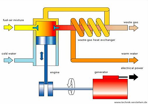
Source: Responsible Business- European e-Learning Module
Description
A. Types of CHP Prime Movers:
| CHP SYSTEM | ADVANTAGES | DISADVANTAGES | AVAILABLE SIZES |
|---|---|---|---|
| Gas Turbine | High reliability. Low emissions. High-grade heat available. No cooling required. | Require high-pressure gas or in-house gas compressor. Poor efficiency at low loading. Output falls as ambient temperature rises. | 500 kW to 300 MW |
| Microturbine | Small number of moving parts. Compact size and lightweight. Low emissions. No cooling required. | High costs. Relatively low mechanical efficiency. Limited to lower temperature cogeneration applications. | 30 kW to 250 kW with multiple unit packages up to 1,000 kW |
| Spark ignition (SI) reciprocating engine | High power efficiency with part-load operational flexibility. Fast start-up. Relatively low investment cost. Has good load following capability. Can be overhauled on site with normal operators. Operate on low-pressure gas. | High maintenance costs. Limited to lower temperature cogeneration applications. Relatively high air emissions. Must be cooled even if recovered heat is not used. High levels of low frequency noise. | 1 kW to 10 MW in DG applications |
| Compression ignition (CI) reciprocating engine (dual fuel pilot ignition) | High speed (1,200 RPM) ≤4MW | ||
| <80 MW for Low speed (60-275 RPM) | |||
| Steam Turbine | High overall efficiency—steam to power. Can be mated to boilers firing a variety of gaseous, liquid or solid fuels. Ability to meet more than one site heat grade requirement. Long working life and high reliability. Power to heat ratio can be varied. | Slow start up. Very low power to heat ratio. Requires a boiler or other steam source. | 50 kW to several hundred MWs |
| Fuel Cells | Low emissions and low noise. High efficiency over load range. Modular design. | High costs. Fuels require processing unless pure hydrogen is used. Sensitive to fuel impurities. Low power density. | 5 kW to 2 MW |
Source: EPA Combined Heat and Power Partnership
B. Features of CHP Technology
Installed Cost
The installed cost for most CHP technologies consists of the total equipment cost plus installation labor and materials, engineering, project management, and financial carrying costs during construction.
Operation and Maintenance (O&M) Cost
Non-fuel operation and maintenance (O&M) costs typically include routine inspections, scheduled overhauls, preventive maintenance, and operating labor. O&M costs are comparable for gas turbines, gas engines, steam turbines, and microturbines, and only a fraction higher for fuel cells.
Start-Up Time
Start-up times represent how long it takes CHP units to get online and be able to provide electricity and thermal output. Start-up times for the five CHP technologies described above can vary significantly depending on the technology and fuel used.
Availability
Availability indicates the amount of time a unit can be used for electricity and/or steam production. Availability generally depends on the operational conditions of the unit.
Thermal Output
The ability to produce useful thermal energy from exhaust gases is the primary advantage of CHP technologies. This value is equivalent to the gross useful thermal output of the CHP system minus the thermal input.
| FEATURE OF CHP TECHNOLOGY | TYPE OF CHP PRIME MOVER | ||||
|---|---|---|---|---|---|
| Gas Turbine | Microturbine | Reciprocating Engine | Steam Turbine | Fuel Cell | |
| Installed Cost ($/kW) | Ranges from 1,200 to 3,300 | Ranges from 2,500 to 4,300 | Ranges from 1,500 to 2,900 | Ranges from 670 to 1,100 | Ranges from 5,000 to 6,500 |
| Non-fuel O&M Cost ($/kWh) | Ranges from 0.009 to 0.013 | Ranges from 0.009 to .013 | Ranges from 0.009 to 0.025 | Ranges from 0.006 to 0.01 | Ranges from 0.032 to 0.038 |
| Start-Up Time | 10 min–1 hr | 60 sec | 10 sec | 1 hr–1 day | 3 hrs–2 days |
| Availability | 93–96% | 98–99% | 96–98% | Near 100% | >95% |
| Uses for thermal Output | Heat, hot water, low-pressure and high-pressure steam | Hot water, chiller, heating | Space heating, hot water, cooling, low-pressure steam. | Process steam, district heating, hot water, chilled water | Hot water, low-pressure and high-pressure steam |
Source: EPA Combined Heat and Power Partnership
C. Economics of CHP
CHP systems are major investments. For instance, a 1 MW reciprocating engine system for a hospital might have a capital cost of around $1.6 million. The cost of a CHP system depends on the complexity of its secondary features, such as heat recovery and emissions monitoring systems. Generally, costs for CHP per kilowatt of capacity decrease as size increases. Given the efficiency gains from CHP, however, some analysts estimate that it can be implemented at a negative cost because cost savings from reduced fuel expenditures will outweigh capital and other project costs over the life of the system.
Despite its high initial costs, CHP is cost-effective and offers a variety of long-term economic benefits:
Offset capital costs: CHP can be installed in place of boilers or chillers in new construction projects, or when major heating, ventilation, and air conditioning (HVAC) equipment needs to be replaced or updated. Additionally, CHP avoids the need to build costly, hazardous high-voltage lines. Based on projections that the U.S. will need to install 137,000 MW of new electric transmission and generation capacity, relying on distributed generation rather than central plants would save $136 billion of capital investment and reduce the cost of new power by about three cents per kW .
Reduced energy costs: The high efficiency of CHP technology results in energy savings compared to conventional, separately purchased power, and on-site thermal energy systems. CHP users are insulated from volatile electricity prices. Moreover, by doubling the useful energy products derived from their fuel, CHP hosts can slash their fuel costs. For instance, the BMW plant in Spartanburg, SC reduced its annual energy costs by $5-7 million after installing two CHP gas turbines in 2009 .Hedge against volatile energy prices: CHP can provide a hedge against unstable energy prices by allowing the end user to supply its own power during times when prices for electricity are very high. In addition, a CHP system can accept a variety of inputs including natural gas, biogas, coal, biomass, and build in fuel-switching capabilities to shield against high fuel prices.
More flexible funding: CHP plants can be activated faster and in more flexible increments than traditional electricity generating units (EGUs). They have a direct linkage between the generation and the consumption to meet the power supply needs that accompany economic growth.
D. Benefits of CHP
CHP offers a variety of commercial and societal benefits; including improved environmental quality, grid reliability, and energy efficiency.
Sustainability
CHP can substantially reduce emissions of carbon dioxide and air pollutants like nitrogen oxide, sulphur dioxide and volatile organic particles. By using the fuel's energy twice, CHP yields one-half to one-third of the emissions of the separate generation of heat and power. According to the U.S. Department of Energy, meeting the Agency's goal to double U.S. installed capacity to 40 GW by 2020 would reduce annual greenhouse gas emissions by at least 150 million metric tons of carbon. CHP also avoids emissions associated with conventional power plants, which are responsible for two-thirds of the nation's annual sulfur dioxide emissions, one-quarter of the nitrogen oxide emissions, one-third of the mercury emissions, and one-third of the carbon dioxide emissions. These emissions contribute to serious environmental problems, including global climate change, acid rain, haze, acidification of waterways, and eutrophication of critical estuaries.
Reliability
CHP systems are relatively small and widely distributed. Because they are located at the point of use, they are not vulnerable to a disruption of the transmission system and can provide emergency power in the case of an outage due to extreme weather events. CHP systems are independently fueled and operated. While such systems can be centrally dispatched, they can also be operated effectively in the event of a disruption to central systems if specially configured for "islanding."
Also, distributed energy resources like CHP reduce electricity infrastructure vulnerability. These features make CHP installations less vulnerable than central power plants to disruption. CHP also generally uses secure natural gas or other domestic fuels, reducing vulnerability to a volatile fuel market. CHP can increase the reliability of a building's power supply - a substantial advantage in today's changing electricity market and high-tech society. A highly reliable power supply is vital to some companies' computing, manufacturing, and research functions and essential for critical infrastructure like hospitals and wastewater treatment plants.
Efficiency
Combined heat and power is an efficient and clean approach to generating power and thermal energy from a single fuel source. The average efficiency of fossil-fueled power plants in the United States is 33 percent, and has remained virtually unchanged for four decades. This means that two-thirds of the energy entering the system is lost as waste heat. However, CHP systems typically achieve total system efficiencies of 60 to 80 percent. Because CHP is more efficient, less fuel is required to produce a given energy output than with the separate production of heat and power.
As an efficiency technology, CHP helps makes businesses more competitive by lowering their energy costs, reducing demand on the electricity delivery system, and reducing strain on the electric grid. Such on-site generation avoids the transmission and distribution losses associated with electricity purchased via the grid from central stations and defers or eliminates the need for new investment. CHP's inherent higher efficiency and elimination of transmission and distribution losses from the central station generator, results in reduced primary energy use and lower GHG emissions. CHP can provide overall energy and CO2 savings on par with comparably sized solar PVs, wind, and natural gas combined cycle (NGCC), and at a capital cost that is lower than solar and wind and on par with NGCC.
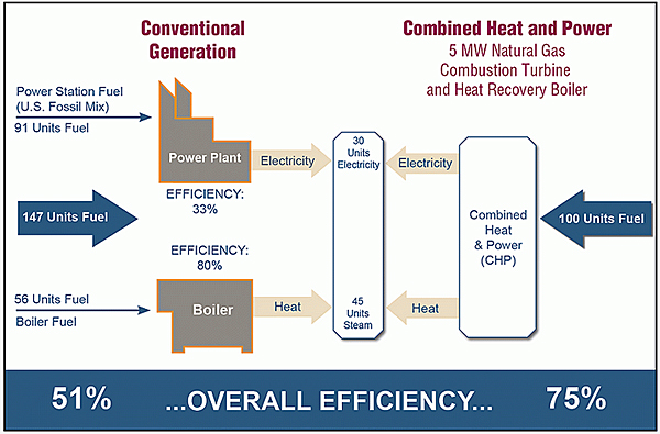
Source: EPA Combined Heat and Power Partnership
Applications
Commercial/Institutional Buildings
Commercial buildings used over 16 quadrillion BTUs of energy in 2000—equivalent to the annual gasoline consumption in the U.S. There is great potential for CHP in large commercial office buildings, supermarkets, hotels, restaurants, and large retail markets. Mixed-use developments are an emerging market for CHP, especially due to the clean, reliable on-site power they provide. Recent ICF projections predict equal technical potential of 65 GW in the industrial and commercial/institutional sectors.
Hospitals
Hospitals are excellent candidates for CHP because they have high electrical and thermal energy needs and because reliability is critical. A 2 MW gas turbine CHP system can provide annual O&M savings of more than $400,000. Also, CHP enhances the quality of power by assuring smooth operation of clinical devices.
District Energy
District energy systems may be installed at large, multi-building sites such as universities, hospitals, airports, and government complexes. District energy systems are a growing market for CHP because they significantly expand the thermal load potentially served by the system. District energy also has a major added benefit of reducing the requirement for size and capital investment in production equipment due to the diversity of consumer loads, enabling more cost-effective CHP.
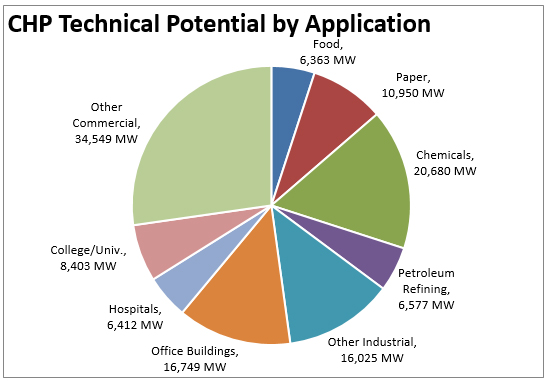
Source: ICF International Internal Estimates, July 2014.
Emerging Issues
Unclear Utility Value Propositions
Since CHP does not depend on central power, it reduces revenue for many investor-owned utilities where business models link sales to cost recovery and revenues. Utility tariff structures and standby rates directly affect onsite CHP generation. Similarly, interconnection processes can delay projects and require costly studies or onerous technical specifications to develop and install a system.
Market and Non-Market Uncertainties
Because CHP equipment requires substantial upfront costs and has a long life (exceeding 20 years), potential hosts must make a long-term financial commitment. Energy efficiency is maximized when a system is sized to match a facility's thermal load. This often results in more power than the host site needs. In some jurisdictions, this excess power production can be sold to the grid, but raises questions about long-term electricity pricing.
Local Permitting and Siting Issues
CHP installations must comply with many local zoning, environmental, health, and safety requirements. This requires interaction with a number of local agencies, including fire districts, water districts, and planning commissions, which are largely unfamiliar with CHP. While CHP systems reduce regional emissions because the facility now produces electricity, on-site emissions will increase, which may prevent hosts from pursuing projects.
Relevant Codes, Standards, and Guidelines
- 26 U.S. Code § 48 (a) (3) (A)
- Distributed Energy Interconnection Procedures Best Practices for Consideration
- Executive Order 13624, "Accelerating Investment in Industrial Energy Efficiency"
- Methodology for Modeling Combined Heat and Power for EAp2/c1 in LEED 2009
- Modified Accelerated Cost Recovery System (MACRS)
Additional Resources
State and Federal Agencies
- California Energy Commission
- DOE Office of Energy Efficiency and Renewable Energy, CHP Basics
- EPA Combined Heat and Power Partnership
- HUD Office of Environment and Energy
- New York State Energy Research and Development Authority (NYSERDA) Combined Heat and Power Systems
Associations and Organizations
- The Combined Heat and Power Alliance
- American Council for an Energy-Efficient Economy
- Center for Climate and Energy Solutions
- Combined Heat and Power Alliance
- Heat is Power Association
- International District Energy Association
- International Energy Agency Technology Collaboration Programme on District Heating and Cooling including Combined Heat and Power
- Pew Charitable Trusts
- State and Local Energy Efficiency Action Network
- World Alliance for Decentralized Energy
Reports
- "Challenges Facing Combined Heat and Power Today: A State-By-State Assessment"
- "CHP: A Clean Energy Solution"
- "Combined Heat and Power: Effective Energy Solutions for a Sustainable Future"
- "Guide to Using Combined Heat and Power for Enhancing Resiliency and Reliability in Buildings"
- The Market and Technical Potential for Combined Heat and Power in the Commercial/Institutional Sector
- "The Opportunity for CHP in the United States
- "Portfolio Standards and the Promotion of Combined Heat and Power"
- "Promoting Combined Heat and Power (CHP) for Multifamily Properties"
- "Standby Rates for Consumer-Sited Resources: Issues, Considerations, and the Elements of Model Tariffs"
Databases
Training
Commander's Guide for Self-Help Success (AMC)
With manpower and funding in short supply, self-help offers wing commanders a way to leverage limited facility improvement resources. Self-help encourages facility users to “take charge” of their offices, living spaces, and recreational areas. The program provides an excellent method to achieve facility improvement and foster a sense of “ownership” and unit pride. By fostering this sense of pride, self-help projects contribute to successful mission completion and improved user care of facilities. To capitalize on this opportunity, the self-help program should:
- establish a “team approach” that actively involves unit commanders and senior NCOs;
- set goals, identify requirements, establish priorities, and designate roles and responsibilities for execution;
- be responsive and customer oriented;
- encourage projects for the “community” like playgrounds, pavilions, and bus shelters.
Commander's Guide to Facilities Excellence (AMC)
Our Installations are small communities where people work and live. Excellent facilities are a critical component of excellent installations. The quality of facilities has significant impact on our ability to support the mission, and to attract, motivate, and retain highly skilled and dedicated people. Investment in outstanding facilities translates to investment in quality people and excellence in operational mission capability. The success of our communities is directly affected by our vision and our efforts. Develop AMC installations to maximize mission accomplishment, optimize use of existing facilities, and provide the most efficient, safe, and professional surroundings possible.
Design standards are the wellspring from which installation quality is drawn. Urban, architectural, and engineering standards form the vision. Maintenance standards help insure that materials and systems give prolonged service and superior life-cycle performance. A facility that is out of context with the base design theme, or located at an incompatible site, is a 50-year mistake. Use this guide as a reference document to achieve success. In short, establish a vision, plan, design, execute, and maintain. Continually survey the base for compliance with our standards and look for ways to improve the community. Excellence is a continuous journey.
Commissioning Authority
Introduction
Within This Page
Commissioning is a standardized process lead by a professional, commonly referred to as a Commissioning Authority (CxA), who is knowledgeable in the design, construction, and operation of systems. The The CxA typically leads a team of system experts trained and certified in the facility commissioning field. There are numerous certification organizations in the industry, recently the Department of Energy (DOE) with NIBS assistance, has established a national certification for commissioning certification organizations. These organizations will be required to perform according to ANSI standards and they must meet ISO/IEC 17024. NIBS recommends that an owner seriously consider the program benefits when acquiring the services of a CxA. The outcome of the process verifies proper operation of commissioned systems and that the requirements set forth by the owner are achieved. By definition, to put something "into commission" means that it is ready for regular use. Historically, commissioning has been used by the Navy to ensure that ships were seaworthy prior to leaving port. At sea, a breakdown would not only be costly to correct, it could potentially be life-threatening. For manufacturers the benefits are also well understood for using commissioning on expensive and sensitive process systems as it ensures safety, reduces waste, and maximizes up-time.
In the construction industry, commissioning or building commissioning was first used on building projects by the Public Works Canada¹. The process of building commissioning was further refined when, several years later, ASHRAE formed the HVAC Commissioning Guideline Committee who then published the HVAC Commissioning Guideline in 19881. In 1998 the United States Green Building Council (USGBC) added commissioning to its Leadership in Energy and Environmental Design (LEED) criteria. A move that, made great strides in promoting the use and acceptance of building commissioning.
Today the role of the building commissioning authority has become a central component to the whole building design process as the built environment continues to include more complicated and interdependent systems and owners focus on energy efficiency to keep operational costs down.
¹History of Commissioning, PECI
Description
Definition of a Commissioning Authority
A commissioning authority (CxA) is a person or firm responsible for the delivery of the commissioning process. Depending on the size and complexity of the project the process may be executed by one person or an entire team. For a team approach there would typically be a person dedicated to managing the process, while others are involved with the more technical aspects of the process.
The knowledge base that a CxA needs to draw from includes information about design, construction, and maintenance. While knowing something about all these elements is critical to being a successful CxA, most professionals will be stronger in one of the three areas. Furthermore, a CxA need not be a design professional or an engineer, with a number of Commissioning Authorities having a background as a test and balance contractor, controls technician, or even facility maintenance. Traditionally the professionals who become Commissioning Authorities do so as a second or third career.
Currently one cannot even obtain a degree in Building Commissioning, so learning about the process typically involves courses or self-study that leads to obtaining one of the industry's certifications. Unlike Architects or Professional Engineers, Commissioning Authorities are not required to be certified to practice building commissioning but most are because it is so often part of any evaluation and selection process for projects. While most certifications focus on the individual there are some that cover the entire firm. For a complete list of certifications refer to the certifications section (below). When looking at the certifications it is important to point out that few of them focus on the technical nature of commissioning systems and instead test applicants on the process. ASHRAE's CPMP certification was the first created specifically to focus on the management of the commissioning process as an entirely new job function, leaving the certification of commissioning authorities to other organizations.
Most Commissioning Authorities often have knowledge and experience related to HVAC and controls. However there are others in the field with different discipline specialties or have experience with specialized building types.
Examples of discipline specialties include:
- Emergency Power Systems
- Building Enclosure (Envelope) Systems
- Communications Systems
- Fire Protection Systems
Examples of specialized building types include:
- Health Care Facilities
- Research Facilities
- Data centers
- Correctional Facilities
Commissioning Authority's Role in Whole Building Design
The Commissioning Authority can and should play a key role in the whole building design process. The CxA should become involved during the pre-design phase or be the first person by the side of the owner. Involvement continues through design and construction, providing continuity as the owner's expert, making sure that their requirements are being met. The primary role throughout the project is to understand the OPR, making sure that these are incorporated into the design, installed during construction, and tested with a completely functional building being returned to the owner. During this whole process the CxA works with the design team to accomplish this.
Designing, constructing, and operating a building is a complex feat that involves input from many different team members. While many of these professionals have high levels of competence they are still prone to the issue of poor coordination and integration due to schedule and budget constraints. This is where the CxA can assist the project team, not only by leveraging their experience and knowledge, but also through project iteration. Commissioning Authorities experience project iteration because of the fact that they do not work on a single project full-time. Instead they have a number of projects in various stages of design, construction, and operation. So problems encountered on one project can be avoided on another, passing it along as a lesson learned.
As a CxA there are four stages of involvement on new construction projects:
Pre-Design—The rationale behind bringing the CxA on before the design team is to provide owners with unbiased opinions of the design teams during evaluation. Before the design team is selected, the CxA assists the owner's staff in the development of the Owner's Project Requirements or OPR. This "living" document is the guideline for the project and holds all the information and requirements that the owner wants to include and/or achieve. It is referred to as a "living" document because it is kept up to date by the CxA throughout the project incorporating any changes that arise. For whole building design this is a critical document that gets everyone on team on the same page and gives the designers specific instructions to follow during their design process.
One approach to evaluating design teams during selection utilizes the OPR by providing it as the key element in the RFQ for design services. Each team is required to provide their BOD in response to the OPR. The BODs are then evaluated to determine which team best understood the Owner's intent for the project. This many times provides a better selection than evaluating teams' project experience that has nothing to do with an owner's current project.
Design—During the design phase the commissioning authority will perform commissioning reviews of the design documents checking to make sure that the project team is following the OPR, that interdisciplinary coordination is occurring, and that maintainability is being designed into the project. Additionally, the CxA will work with the design team to develop commissioning specifications that will inform contractors what their responsibilities will be during construction. This all leads to a design that is clear to the contractor and easy to take care of.
Construction—The CxA contributes to the whole design process during construction as they visit the site for observing equipment installation, ensuring that the design documents are being followed, and communicating information back to the design team regarding issues. These visits are focused on the commissioning aspects of the project and do not replace any construction administration responsibilities that the design team may have. In addition to assisting the design team, the CxA can advocate for the contractors by pushing for resolution of field issues that could potentially lead to construction delays. The key result of site inspections is early detection and resolution. Not only is this appreciated by the team, but it saves money for the project overall. Once all the systems have been installed the CxA will proceed to test the equipment and systems, so when the building is finally turned over to the owner it is running smoothly. It is wise for the owner to include the O & M staff for the building on the commissioning team. Their participation on the team during construction and acceptance activities will greatly enhance their knowledge of the proper operation of the facility systems.
Operations—In this phase the CxA works with the maintenance staff to understand the installed systems through training and documentation. This is a crucial step, because even the most advanced design in the world will be reduced to its simplest form to match the level of understanding of the building operators. This is why it is so important to include the maintenance staff in the whole building design process. Keep them in mind when selecting equipment and creating sequences of operation for equipment. For the conclusion of the project, during the 10-month post-construction walk-through, the CxA will be involved with the team to make sure that any issues are resolved prior to the end of the warranty period.
Commissioning Authority Strategies for Achieving Whole Building Design Objectives
While not involved with all of the whole building design objectives there are a few where the CxA plays an important role.
Functional/Operational—At the core of the Commissioning Authority's project role is verifying that the building and the systems it contains are functional, and that they can be maintained for the life of the equipment. Verification is done through the use of an operational script specifically written for the project that follows the engineer's sequence of operation. This script is known as the Functional Performance Test (or FPT), and contains scenarios like equipment start-up, changes in operating conditions, failure modes, restorative modes, safeties, and alarms. Once written, this same form is able to be used by the facility's staff in the future to ensure that the equipment is still operating according to the original design parameters. These scripts are critical in the on-going commissioning process used by the facility staff to maintain proper facility operation for the life of the building.
Productive—Commissioning impacts productivity by verifying that the equipment is operating properly and that the sensors in the inhabited spaces are reading accurately by checking calibration. A second way that productivity is affected by the CxA is by establishing a functional building; this allows the maintenance staff time to perform their regular duties instead of handling complaints and other issues brought to them by the occupants. When staff gets into a "fire-fighting" mode they often delay regular equipment maintenance and apply temporary changes to the building system that are often left in place and masking larger underlying issues and further hindering efficient system operation.
Secure/Safe—Even though they are not large energy consuming systems, life safety systems should be commissioned. These systems exist solely to protect the lives of the facility occupants and proper operation is essential. If not tested, and they are not operating properly, this may not be discovered until it is too late. When the commissioning process includes security or other access systems, verification of these will provide the building owner with piece of mind knowing that they are operating properly and that their staff has received adequate training to use them.
Sustainable—Without proper commissioning, sustainable and energy efficient operation of a building would be unlikely. From the drawing and installation review, to the equipment testing, and through the maintenance staff training, the CxA establishes an important operational baseline that the owner and their staff can reference while maintaining a sustainable and energy efficient facility.
Interaction with Others
It is important that the owner hire the commissioning authority directly. This not only allows the commissioning authority access to the owner and their requirements for the project, but also puts them on a peer level with design and construction teams. Being an equal in these teams is critical because it means that any issues will be given the attention they need without being subjugated. The CxA also needs to take care not to overstep their bounds, understanding and following the proper lines of communication for the project, making suggestions and raising questions, rather than being critical of the engineering and directing construction changes.
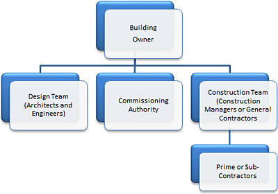
A typical project organizational chart
Communication is the top skill for a CxA and should be able to do so on three distinct levels. The first is at an executive level, where the CxA will be communicating with the owner, becoming empathetic to their requirements and their staffs' ability to operate the building. Next is developing a rapport with the design team by effectively communicating that the CxA is their ally not an adversary. It helps to have an attitude of "win-win", leading designers to discover the CxA's intent, and ultimately assisting them as they put together a quality set of construction documents. Lastly are the contractors, the people that bring life to the drafting and create the physical reality of the building. Communicating with these craftsmen requires an understanding of budgets, schedules, and construction methodologies. Issues in this phase are often best communicated face-to-face and as early in the construction process as possible. Also take time to listen to them as they often have great suggestions and insight regarding the design or layout that the team might have missed. Communications throughout the commissioning process, whether a formal report or a casual conversation over a cup of coffee, cannot be stressed enough as a skill.
Emerging Issues
Some of the emerging issues in the discipline of Commissioning Authorities include:
Slow Market Acceptance Outside of LEED
The Leadership in Energy and Environmental Design (LEED) rating system has had both positive and negative effects on the commissioning industry. Positive from the recognition and business development stand point, but negative because it has caused commissioning to be viewed as a commodity rather than a custom solution to fit an owner's needs. Additionally, it has trained design and construction teams to think of commissioning as two separate services (fundamental and enhanced) rather than a unified process which then requires reeducation, especially when discussing non-LEED projects. Owners not striving for LEED and unfamiliar with commissioning also need to be educated as to its benefits instead of dismissing it when faced with a tight budget. In the end, owners will realize that they can pay for commissioning now, or they can pay for energy and other inefficiencies later.
Lack of Training Beyond the Commissioning Process
Upon entering this discipline one discovers that there are a number of resources to learn about the process of commissioning. Beyond this basic knowledge lies a gap in practical training. Experience and in-house expertise become the standard teachers at this stage which then begs the question, "Can you teach experience?" Commissioning Authorities that fail to gain this practical experience are in danger of becoming paper pushers and will bring little value to a project. A large opportunity exists for the organization that can bring this type of hands-on knowledge to this discipline.
Litigation
When first learning about the commissioning process it is made clear that it is focused on helping owners inherit buildings that meet their requirements and function properly. Concurrently, the use of words like ensure and guarantee when referring to building operation and one's work are discouraged. As a discipline, CxAs are not responsible for the design or installation, and because of this their liability is limited. However, anyone who has been involved with construction knows responsibility can be hard to assign when something is not right. Everyone connected to the project becomes involved when litigation occurs and the commissioning authority is no different. Their involvement commonly takes the form of providing expert testimony and producing documents that will be used in the case. Even when not affiliated with the project some commissioning firms become involved by providing expert witness services. As a commonly touted benefit of litigation avoidance, commissioning may also be beneficial to the project should litigation occur.
Relevant Codes and Standards
- ASHRAE Guideline 0, The Commissioning Process—The industry accepted model Commissioning Guideline.
- ASHRAE Guideline 189.1, Standard for the Design of High-Performance Green Buildings Except Low-Rise Residential Buildings
- ASHRAE Standard 202, The Commissioning Process for Buildings and Systems
- ASTM Standard E2813, Standard Practice for Building Enclosure Commissioning
- The Building Commissioning Guide by U.S. General Service Administration.
- CALGreen
- ICC IgCC® International Green Construction Code®
Additional Resources
WBDG
Project Management
Project Planning, Delivery, and Controls, Project Delivery Teams, Select Appropriate Design Professionals, Risk Management, Building Commissioning, Determine Project Performance Requirements, Commissioning Document Compliance and Acceptance, Owner's Role and Responsibilities in the Commissioning Process
Government Agencies
- California Commissioning Collaborative—a group of government, utility, and building-services professionals committed to developing and promoting commissioning practices in California
- Commissioning For Better Buildings in Oregon, Oregon Office of Energy / PECI, 1997. New construction overview, benefits, process and case studies.
- Federal Energy Management Program—Offers programs and resources for energy efficiency in operation of federal facilities.
- Oregon Department of Energy—Benefits of Commissioning, case study, tool kit of new and existing commissioning application materials, and the full text of Commissioning for Better Buildings in Oregon
- US Department of Energy, Energy Efficiency & Renewable Energy (EERE), Energy Efficiency Policies and Programs—Commissioning
Organizations
- AABC Commissioning Group (ACG)—ACG National Headquarters, Phone: (202) 737-7775. Association of certified, independent commissioning professionals.
- Association of Energy Engineers (AEE)
- ASHRAE—A leading organization in the development of standardized commissioning guidelines
- Building Commissioning Association (BCxA)—A leading professional association for membership and certification of building commissioning practitioners
- Building Services Commissioning Association (Japan)
- Commissioning Specialists Association (UK)
- Hong Kong Building Commissioning Centre
- National Environmental Balancing Bureau (NEBB)—Certification program and manuals. 8575 Grovemont Circle, Gaithersburg, MD, 20877. Phone: (301) 977-9589.
Certifications
ACG (AABC Commissioning Group)
ACG was formed in 2005 as a new entity focused on building commissioning. While it shares a commitment to independence with the Associated Air Balance Council (AABC), it is a separate organization. ACG offers two certifications. The CxA—an ANSI-accredited, Dept. of Energy Better Buildings®-recognized certification—is focused on the experienced professional, while the CxT is for applicants who still need more experience & training. (ACG’s subsidiary, the Energy Management Association, also offers a certification in commissioning-based energy management, the EMP.)
AEE
AEE has four certifications available. The CBCP was the original certification, followed next by the EBCP for those professionals focused more on existing buildings rather than new construction. Recently they have added the CBCF and the CBCPM for firm or professionals that wanted to further distinguish themselves.
- CBCP: Certified Building Cx Professional
- CBCF: Certified Building Cx Firm
- EBCP: Existing Building Cx Professional
ASHRAE
ASHRAE developed their certification in close collaboration with APPA, BCA, IES, NEBB, SMACNA, TABB, and the University of Wisconsin - Madison and closely followed the rigors of the ANSI criteria. ASHRAE's intent was to establish a certification specifically focused on the individuals who would manage the process of commissioning for a project, rather than the technical aspects of commissioning.
BCA
The only organization solely dedicated to the field of building commissioning, they developed the CCP certification as a high benchmark for professionals. Later, to meet the need for a more entry-level certification they developed the ACP.
NEBB
The NEBB commissioning certification process follows closely their process for becoming certified in testing and balancing. Anyone can take their certification courses, which cover a number of different building systems but they will only certify firms. To accomplish this firms must first meet specific qualifications and be approved by the organization. Additionally, a certified firm must have at least one qualified supervisor who has also met the individual requirements of the supervisor position as described by NEBB.
TABB
The TABB Commissioning Supervisor is certification that is not commonly seen in the industry.
University of Wisconsin
The University of Wisconsin-Madison has a unique certification process. Applicants who do not yet have sufficient professional experience in the commissioning process to qualify for one of the more advanced certifications will receive accreditation as a QCxP. This certification is then valid for five years to allow the applicant time to acquire the necessary experience for one of the other certifications.
- Qualified Commissioning Process Provider
- Building Enclosure Commissioning Certificate
- Qualified Commissioning Process Provider Certificate
Publications
- ACG Commissioning Guideline
- Continuous Commissioning Guidebook for Federal Energy Managers, Federal Energy Management Program (FEMP), October 2002.
- Contractor Quality Control and Commissioning Program—Guidelines and Specification, Montgomery Co. Gov., St of Maryland, 1993. 301-217-6071.
- Design Phase Commissioning Handbook National Environmental Balance Bureau (NEBB), First Ed., 2005
- ER 1110-345-723 Total Building Commissioning Procedures , March 2017.
- HVAC Systems Commissioning Manual, Sheet Metal and Air Conditioning Contractors' National Association (SMACNA). SMACNA, 4201 Lafayette Center Dr., Chantilly, VA 22021.
- Laboratory HVAC Systems: Design, Validation and Commissioning ASHRAE collection of 11 papers, 1994. ASHRAE Publications Dept., 1791 Tullie Circle, NE, Atlanta, GA 30329.
- NASA Reliability Centered Maintenance Guide for Facilities and Collateral Equipment
- Planning and Design Services: Commissioning Goals by Washington State Department of Enterprise Services, February 27, 2012.
- A Practical Guide for Commissioning Existing Buildings by Tudi Haasl of Portland Energy Conservation Inc. and Terry Sharp of Oak Ridge National Laboratory, April 1999.
- Procedural Standards for Whole Building Systems Commissioning of New Construction , Third Edition, 2009, NEBB.
- Procedural Standard for Retro-Commissioning of Existing Buildings National Environmental Balance Bureau (NEBB)
- PWGSC Commissioning Manual (CP.1) by Public Works Canada. Phone: 819-956-3972.
- Thermal Energy Storage (TES) Commissioning Guidelines, California Institute for Energy Efficiency, San Diego State University, 1991. San Diego State University, Energy Engineering Institute, San Diego, CA 92182.
- UFGS 01 91 00.15 Total Building Commissioning (Navy-only)
- UFGS 01 91 00.15 10 Total Building Commissioning (Army and Air Force-only)
- UFGS 02 62 16.16 10 Commissioning and Demonstration for Soil Vapor Extraction (SVE) Systems
Training and Other Resources
- WBDG14 Building Commissioning Principles and Strategies—This course will provide you with an introduction to the Building Commissioning process with a special focus on how to determine the performance requirements and plan the commissioning process.
- ACG: AABC Commissioning Group—Training and certification at their annual conferences
- AIA C203-2017 (formerly B211-2007) Standard Form of Consultant's Services: Commissioning—This fixed scope of services requires the architect to develop a commissioning plan, a design intent document, and commissioning specifications, based on the owner's identification of systems to be commissioned.
- ASHRAE Learning Institute—offers an ongoing series of commissioning workshops
- The Association of Energy Engineers
- Building Commissioning Association
- California Commissioning Collaborative—Resource Library
- Center for the Built Environment (CBE), Berkeley
- Collaborative for High Performance Schools
- Commissioning Specialists Association: Guidance Notes
- Engineered Systems Magazine—Commissioning Column by Rebbeca T. Ellis
- Functional Testing and Design Guides, Portland Energy Conservation, Inc.
- GSA Sustainable Facilities Tool (SFTool)—SFTool's immersive virtual environment addresses all your sustainability planning, designing and procurement needs.
- TECHINFO-USACE Technical Information website
- Texas A&M Energy Systems Laboratory—Retro-commissioning process and software, for sale.
- University of Michigan Architecture, Engineering and Construction, Building Commissioning Documents
Mechanical Commissioning - University of Wisconsin-Madison, Department of Engineering Professional Development—Offers several commissioning courses and Commissioning Process Certifications.
- Virtual Cx—A website that is a resource for commissioning articles, links, and other helpful info.
Commissioning Challenges and Emerging Issues
Introduction
Within This Page
Today's challenges across the building industry are the precursors of tomorrow's solutions. As technologies and complexity in the built environment trend toward better design, construction and operation, the following represent high-visibility issues that affect commissioning as an increasingly broad cross-functional practice.
Code Applications for Commissioning
Many local and national energy codes and green codes now require the performance of commissioning and specific documentation. Some of these codes have variations in the level of commissioning required to be integrated into the project. These requirements should be analyzed during pre-design and integrated into the OPR and commissioning process to satisfy jurisdictional and selected program requirements.
Increasing Building and Construction Technologies
In recent years the design and construction of buildings and systems have become increasingly complex, particularly with respect to the systems and controls included in commissioning requirements. These complex systems make the OPR process and the application of commissioning critical to the successful completion and operation of facilities and systems. This will also increase the technical specifications in the OPR and the commissioning process and require even more careful requirements for the design, verification, and documentation.
Building Performance Reporting
Legislation and market demand for measuring and reporting facility resource efficiency, such as voluntary rating programs such as the U.S. DOE ENERGY STAR Program, LEED®, Green Globes, WELL™, BREEAM and many others have made the design, construction, and performance measurement of high efficiency building systems increasingly important. These certification programs are often complex and require OPR and commissioning documentation for verification and credits. As concern for energy and carbon reduction grows, these requirements will also continue to increase.


Facility managers at the United States Institute of Peace (USIP) Headquarters use ENERGY STAR tools and resources to prioritize retrofits and ensure efficient operations. Photo Credits: USIP
Cx Reporting Technology — Digital Documentation Systems
The OPR and commissioning process require extensive documentation and reporting. Digital systems are available in the marketplace to facilitate that process. The functionality, ease of use, and accuracy of many of these programs vary; careful analysis of reporting system capabilities is essential before and during application.
Integration of Health Requirements with Energy and Sustainability
In recent decades numerous sustainability, green building, and health-related programs for buildings and occupied spaces have been established, promoted, and even mandated. Some directly require commissioning. Most are sufficiently complex that they require building system performance and reporting that makes commissioning essential. These programs and requirements will continue to gain attention and regulatory consideration, particularly in terms of safe and healthy facilities.
Integrating Cx into Building Operations
As can be seen in these commissioning pages, the design, construction, and commissioning of facilities directly affects the performance of the facility and systems for the life of the building. To maintain the high efficiency operation, the use of ongoing commissioning is evolving and becoming even more important as discussed in Existing Building Commissioning and Ongoing Commissioning.
Integrating AI into FDD and Operations
The introduction of Artificial Intelligence (AI) automation and analytics into various fault detection and diagnostic (FDD) systems is opening the door to allowing building systems to make minor systems adjustments on their own (e.g., temperature set points, reset downed equipment, etc.). This can significantly reduce the amount of time operators or consultants need to spend making these adjustments. The technology is currently being tested and piloted.

Artificial Intelligence is becoming increasingly more prevalent in the design, construction, and management of buildings. Photo Credit: Princy A.J./Research Dive
Owner Versus Building User
Many projects are core-and-shell made ready for a "tenant," wherein the original design included basic systems developed on minimal bases, but the tenant has requirements that are greater than the original design concept. For example: a core-and-shell warehouse building may have basic air and electrical needs, but the user is planning to use the facility to store specific products that fall under the jurisdiction of the FDA.
Advanced Training for Operations and Maintenance Personnel
As technical and technology-based building commissioning and even regulatory requirements for sustained high performance depend increasingly on data analytics, facility staff will require new knowledge, skills and abilities to be capable of operating and maintaining their buildings' systems. Current training sources for ongoing commissioning are scattered at best, and vary widely in scope and scale.
Additional Resources
See the Additional Commissioning Resources page for more information.
Commissioning Documents: Process, Contents, and Acceptance
Introduction
Within This Page
The purpose of commissioning (Cx) documentation is to serve as the historical record of the "what, why and how" of key delivery team decisions throughout the planning and delivery process. Commissioning documentation becomes the road map for the success criteria to be met by facilities that are put in service.
Commissioning documents the establishment of standards of performance for building systems and verifies that designed and constructed work meets those standards. This page describes the commissioning documentation development process, content requirements, acceptance and usage, and provides detailed descriptions of common commissioning documentation deliverables.
Commissioning is a team effort to document the continuity of a building project as it moves from one project phase to the next. Designated team members are responsible for specific documents during the various phases. The acceptance, maintenance, and utilization of the documents varies by usage and phase. Since documentation for each project varies, these activities and responsibilities need to be planned and designated in the project Owner's Project Requirements (OPR). When the entire project delivery process is documented in a consistent manner, a historical perspective is created that explains the iterative process of determining the agreed-to project requirements at each step of the development process.
Documentation Process
The development of documentation for a new construction project and the commissioning process must be carefully planned, coordinated, organized, and controlled. Commissioning documents are project-phase dependent. The process starts at project inception with determination of project requirements and spans all phases from pre-design through testing, acceptance, and operations.
Team member responsibilities for the documentation must be planned by the Owner or project/facility management personnel and carefully supervised. The documents must be organized and accepted, and a current document retention process must be developed and enforced. Typical assignments throughout the documentation process are shown in the Documentation Matrix below.
Each project will require different documentation specifics. Thus, while the titles or topics may be the same, the specific requirements must be developed and documented for the task and project at hand. This variability requires the careful planning and supervision by the Owner's team and the commissioning team. Review and acceptance processes must be in place to assure the accuracy of the documents and report. This control increases accuracy and the value to the project and ultimately increases the success of the project.
Commissioning documentation is generated throughout the project delivery process. The content of commissioning documents varies with each project, and must be created specifically for the project needs as defined in the OPR. Upon completion, each document is reviewed and accepted as determined by project requirements and retained with the other project documents for building operation and maintenance.
In the planning and development phase of a project, the OPR document is developed. Documents created for specific functions and documentation of results are collected by the responsible team member and processed by the required procedures on the necessary schedules. At post-occupancy, commissioning documentation becomes the benchmark to ensure that the building can be efficiently operated and maintained. This assembly of information is usually organized in a set of documents called the Building Systems Manual.
Documentation Matrix — Table A–1
The following matrix from ASHRAE Standard 202–2018, Commissioning Process for Buildings and Systems (by permission) summarizes the commissioning documents by project phase and indicates some of the information sources along with the usual acceptance and the intended usage of each document.
| DOCUMENTATION PHASE | DOCUMENT | INPUT BY | PROVIDED BY | REVIEWED/ APPROVED BY | USED BY | NOTES |
|---|---|---|---|---|---|---|
| Project Initiation / Pre-Design / Design | Owner's Project Requirements | Owner, CxP, O&M, Users, Design Team | Owner, CxP or Design Team | Owner | CxP, Design Team | Design Team may not be hired yet See BCxA New Construction Best Practices |
| Initial Commissioning Plan | Owner, Design Team, CxP | Owner or CxP | Owner | CxP, Owner, Design Team, Construction Team | Design Team may not be hired yet. | |
| Systems Manual Outline | Owner, O&M, CxP | Owner or CxP | Owner | Design Team, Construction Team | Should follow Guideline 1.4 | |
| Training Requirements Outline | Owner, O&M, Users, CxP, Design Team | Owner or CxP | Owner, CxP | Design Team, Construction Team | Should follow Guideline 1.3 and as defined | |
| Issues and Resolution Log Format | Owner, or CxP | Owner, CxP, | Owner | CxP, Design Team | May be only format at this phase | |
| Pre-Design Phase Commissioning Process Report Format | Owner, CxP | CxP | Owner | Owner, Design Team | Follow requirements in standard | |
| Design | Owner's Project Requirements Update | Owner, CxP, O&M, Users, Design Team | Owner, CxP | Owner | CxP, Design Team | |
| Basis Of Design | Design Team | Design Team | Owner, CxP | Design Team, CxP | ||
| Construction Specifications for Commissioning | Design Team, CxP, Owner, O&M | Design Team and/or CxP | Owner | Contractors, CxP, Design Team | May also be provided by Project Manager / Owner's Rep. | |
| Systems Manual Outline-Expanded | Design Team, CxP, O&M, Contractor | Design Team or CxP | Owner, CxP | Design Team, Contractor | Contractor may not be hired yet. | |
| Training Requirements in Specifications | Owner, O&M, Users, CxP, | Owner, CxP, O&M | Owner | Design Team | Contractor may not be hired yet. | |
| Design Review Comments | CxP | CxP | Design Team, Owner | Design Team | ||
| Issues and Resolutions Log | CxP | CxP | Design Team, Owner | CxP, Design Team | ||
| Design Phase Commissioning Process Report | CxP | CxP | Owner | Owner | Close of Phase report | |
| Owner's Project Requirements Update | Owner, O&M, Users, Design Team | Owner, or Designer | Owner | CxP, Design Team, Contractors, Owner | ||
| Construction | Basis of Design Update | Design Team | Design Team | CxP, Owner | Design Team, CxP, Owner | |
| Commissioning Plan Update | Design Team, CxP, Owner, Contractor | CxP | Owner | CxP, Owner, Design Team, Contractors | ||
| Submittal Review Comments | CxP | Design Team | Design Team | Contractor | ||
| System Coordination Plans | Contractor, Design Team, CxP | Contractor | CxP, Design Team | Contractor, CxP | ||
| Evaluation | CxP | CxP | CxP, Design Team | Contractor | ||
| Checklists | Contractor, Design Team | Contractor | Contractor | |||
| Cx Progress Reports | CxP, Contractor | CxP | CxP, Owner | Contractor | ||
| Test Procedures | CxP, Contractor, Design Team | CxP | CxP, Design Team | Contractor | ||
| Specified Test Data Submittals | Owner, CxP, Design Team | CxP, Owner, Contractor | CxP, Design Team | Project Team | ||
| Commissioning Meeting Agendas and Minutes | CxP | CxP | All | All | ||
| Training Plans | Design Team, CxP, O&M, Contractor | Contractor or CxP | Owner, CxP | O&M, Users, Contractor | ||
| Systems Manual | Design Team, CxP, O&M, Contractor | Contractor or CxP | Owner, CxP | O&M, Users | See ASHRAE Guideline 1.4 | |
| Issues and Resolution Log | CxP | CxP | N/A | Project Team | ||
| Progress Report | CxP | CxP | Owner, Design Team | Project Team | ||
| Preliminary Construction Commissioning Report | CxP | CxP | Owner | Owner | Prior to Occupancy | |
| Owner's Project Requirements Update | Owner, O&M, Users, Design Team | CxP or Designer | Owner | CxP, Owner Contractors | See ASHRAE Guideline 0.2, BCxA Existing Building Best Practices. and Ongoing Commissioning Best Practices for post-occupancy Cx | |
| Occupancy and Operations | Basis of Design Update | Design Team | Design Team | CxP, Owner | Owner, CxP, O&M | |
| Maintenance Program | Owner, O&M, Contractor, CxP | Owner or CxP | Owner, CxP | O&M, Users | ||
| Test Procedures | CxP | CxP | Design Team, CxP | Contractor, O&M | See Systems Manual | |
| Updated Issue and Resolution Log, Test Data Reports | CxP | CxP | N/A | Project Team | ||
| Final Issues and Resolution Log | Project Team | CxP | Owner | Owner | ||
| Prefinal Report | Project Team | CxP | N/A | Owner | ||
| Final Commissioning Report | Project Team | CxP | N/A | Owner | Final Report | |
| Re-Commissioning Plan | O&M, Users, CxP | CxP or Owner | Owner | Owner | ||
| Ongoing Commissioning Plan, if required | Owner, O&M, Contractor, CxP | Contractor, CxP | Owner | Owner, O&M |
EBCx Documentation
The development and delivery of documentation for an existing building commissioning (EBCx) project is similar. Instead of using the OPR, the CxP and Owner begin with a baseline document, the Current Facility Requirements (CFR). If a CFR does not exist, which is sometimes the case, one will be developed and updated throughout the EBCx process, resulting in a document that would be used as a baseline for current facility and system assessment, verification, tune up and upgrade implementation, and ultimate hand off to facility operation that meets current requirements. The CFR is also necessary for future facility, systems and assemblies' renovation or ongoing commissioning (OCx). The CFR must be reviewed and updated on a regular basis to facilitate facility operation to meet Owner and occupant performance requirements. Existing Building Commissioning, lists variants from new construction commissioning deliverables.
Documentation Contents
The following is a list and descriptions of typical commissioning documents:
Owner's Project Requirements (OPR). The OPR is first and possibly the most important document an Owner and CxP prepare together, to ensure the commissioning process meets the Owner's goals. The OPR defines the expectations, goals, benchmarks and success criteria for the project. The OPR must be developed by the Owner and the CxP should be tasked with assisting the Owner's team to develop this document. The CxP typically assists the Owner in identifying the facility's requirements regarding such issues as energy and water efficiency, indoor environmental quality, staff training, and operations and maintenance. An effective OPR incorporates input during the pre-design phase from the Owner, design team, operations and maintenance staff and end users of the building, and is updated throughout the project. An OPR is developed in explanatory terms for an Owner/user audience. The OPR is updated throughout the project design, construction, and initial operation as necessary and each revision should be accepted by the Owner or representative. Determining Project Performance Requirements details the items and information that are included in an OPR.
Basis of Design (BOD). The BOD is a narrative and analytical/technical documentation prepared by the design team, along with design submissions to explain how the OPR is met by the proposed design. It describes the technical approach used for systems selections, integration, sequence of operations, controls, and codes and standards application focusing on design features critical to overall building performance. A BOD is developed by the design team in more technical terms. As a best practice to close any gaps, the design team will review the OPR along with BOD design review comments from the CxP. The Owner or representative must review and ultimately approve the BOD to facilitate OPR compliance.
Design Review Comments. The CxP will review the BOD for compliance with the OPR and provide design review comments to the design team, to verify that the OPR and BOD are met and to facilitate the commissioning process and building operations. In particular, the reviews confirm that there are adequate access points, test ports, and control features. Reviews also verify that energy and water efficiency, systems operation, control sequences, maintenance capability, training and O&M documentation requirements are consistent with the OPR and BOD. A commissioning review of the design is not the same as a technical peer review. The commissioning review is intended to review aspects of the design that few others typically review such as system access, controls application, and testing and maintenance access and planning. The CxP design review must be sent to and addressed by the appropriate design team and the results accepted by the Owner or representative.
Commissioning Plan. The initial commissioning plan should be assembled at the predesign phase and include planning for both the design and construction activities. The Cx Plan outlines the scope of the commissioning activities along with responsibilities, schedules, communication requirements, and procedures. The Cx Plan is updated throughout the project and will include the listing of required documents with assignments of responsibility, updated commissioning schedules, installation, verification and commissioning checklists, and report formats. The Cx Plan is distributed to the Owner for review and to the commissioning team members and contractors for application.
Commissioning Specifications. The commissioning specification sections are developed by the design team with assistance of the CxP to convey details of the commissioning process, and contractor and supplier responsibilities to the construction team. Each commissioned system should have a commissioning specification section that includes requirements and formats for drafting, application, and completion of system checklists. A draft set of system readiness checklists and verification test procedures ideally includes the commissioning specification to communicate (to the bidding contractor and others) the processes and level of rigor expected during the system installation and testing phase of commissioning. System readiness checklists are detailed checklists for documenting that each system is prepared for testing. Verification test procedures are a detailed set of instructions and acceptable results for thoroughly testing each system. The supplier and contractor installation, startup, and testing checklists shall be reviewed by the CxP for integration into the commissioning process and ultimately the Systems Manual when complete.
Certification Documentation. Owners sometimes require their facilities to achieve building performance rating certifications, sustainability program application, and code compliance. When such performance certifications are required as part of a design or construction contract, they become critical to an Owner's project expectations. They may, and in some cases must (in order to achieve the rating status sought) be commissioned. These requirements along with the processes and responsibilities should be included in the OPR and necessary construction documents.
Submittal Review Comments. Concurrent with the design team and Owner review, designated commissioning team members review products and systems submittals for compliance with the design and OPR. Special attention should be given to avoiding vagueness, substitutions, and proposed deviations from the contract documents, OPR requirements, and BOD documentation. Submittal review comments on commissioned systems will often generate issues for coordination between integrated systems, equipment, and technologies. These issues need to be addressed before equipment installation. Acceptance of submittals typically remains with the design team. The Cx review should also be utilized to prepare the functional testing procedures, check lists, and documents.
Field Observation Reports. Commissioning Field Observation Reports should be prepared regularly to document progress of the work on commissioned building systems and assemblies. These reports will normally identify functional issues, integration issues or operational issues that are then captured in Issues and Resolution Logs for discussion and clarification of performance expectations, integration issues, or operational issues. The construction delivery team (and Owner's representative/construction manager, if applicable) will also prepare reports pertaining to all building systems and components. These field observation reports shall be sent to the CxP and to other entities as required by the OPR and Commissioning Plan.
Test Data Reports. Test data reports contain results of the testing and field observation and include field observation reports, functional and performance test (FPT) reports, performance testing, and other test results specified for the commissioned systems. These are distributed and reviewed in accordance with commissioning plan procedures. Final copies are included in the Systems Manuals.
Issues and Resolution Logs and Reports. Issues and resolution logs and reports are a formal, ongoing record of problems or concerns—and their resolution—that have been raised by members of the construction and commissioning teams during the course of the commissioning process. Issues logs should be included in commissioning reports because, along with meeting minutes, design review comments and field observation reports, they explain the thought sequence and rationale for key decisions in the commissioning process. The issues log should be formatted to facilitate the documenting, tracking and resolution of commissioning related issues. Issues logs typically contain, at a minimum, a detailed description of the issue, date identified, party responsible for corrections, issuing agent, and completion status. All findings are documented and distributed as they occur. The Issues and Resolution logs are normally generated by the CxP and distributed according to the OPR requirements, the Cx Plan, and/or agreement with the Owner and Cx Team. It is the responsibility of the Owner to review and approve all issue resolution decisions. The current or final Issues Logs are included in the commissioning reports with a copy included in the Systems Manuals.
Systems Manual. The Systems Manual provides the information needed to understand and properly operate and maintain the building systems and assemblies. It should be in clear language that is understandable by people unfamiliar with the project or systems. The Systems Manual is ideally delivered to the Owner in electronic indexed (bookmarked) and hyperlinked format that can be updated throughout the life of the building. ASHRAE Standard 202–2018, The Commissioning Process for Buildings and Systems, and Guideline 0–2019, The Commissioning Process, and Guideline 1.4–2019, Preparing Systems Manuals for Facilities, recommend that the Systems Manual include the OPR, BOD, submittals, asbuilt drawings, specifications, certifications, Facility Guide for the building operation parameters, operational and maintenance requirements and O&M manuals, training documents and commissioning documentation with testing and verification reports and final issue and resolution logs. This information should be organized in the Systems Manual for ease of access and use by building management and appropriate operational and maintenance staff. The systems manual should be assembled by the general contractor or CM with CxP review with all documents available before training begins, and utilized as part of the training process.
Training Documentation. Training program and requirements should be defined in the project OPR. During the design phase, training requirements for facility managers, operations and maintenance personnel, and occupants must be identified relative to commissioned systems, integrated building features, and equipment. These training requirements should be included in the project specifications in all appropriate sections. It is critical that the operations and maintenance personnel have the knowledge and skills required to operate a facility in accordance with the Owner's Project Requirements, functional plan and its designed intent. The training plan and training materials should include where to find systems information in project documentation. Training materials should be retained and updated for periodically scheduled training activities and included in the Systems Manual.
Seasonal Testing. Due to climate conditions, not all systems can be fully tested during the construction phase. For example, testing a boiler system might be difficult in the summer and testing a chiller and cooling tower might be difficult in the winter. The performance and testing of solar photovoltaic systems are also dependent on seasonal conditions. Commissioning plans should therefore provide for multi-season testing to allow testing, balancing, and optimization of integrated systems under the varying actual operating conditions. This testing often extends into the initial operation phase of the project which requires the updating of reports until the functional tests are satisfactorily completed. The final completed testing and reports should be included in the updated Systems Manual.
Final Commissioning Report. The commissioning requirements, process, documentation, and findings are incorporated in a final commissioning report that is transmitted to the Owner for review and acceptance and accompanies the construction contractor's turn-over documentation. Commissioning documentation that will be included in the Final Commissioning Report is normally listed in a table format with responsibilities of individual team members who will prepare, review, and accept the results and documentation. ASHRAE Standard 202–2018, The Commissioning Process for Buildings and Systems, and Guideline 0–2019, The Commissioning Process, recommend that the commissioning reports be included with O&M manuals in a Systems Manual. Commissioning report contents should be clearly defined in commissioning plans and include an executive summary, a narrative of the commissioning process and Cx process results. In addition, the report should include the design and submittal review comments and resolution, meeting minutes from all commissioning related meetings, corrective action reports, blank verification test reports for future use, completed training forms, completed installation and system readiness and startup checklists, current Issues and Resolution logs, and tests and field observation reports for commissioned systems, equipment, assemblies, and building features. Due to project schedule and/or seasonal testing requirements, it may be necessary to provide a preliminary commissioning report for interim project or code compliance that includes all available data along with the summary of requirements for commissioning completion. The preliminary report is updated with final commissioning results, transmitted to the Owner and included in the updated Systems Manual. The Final Cx Report should include the results of the off-season and completion verification Cx documentation.

Installing solar panels on the roof of a new project, which may need to be commissioned for multi-seasonal conditions. Photo Credit: 186561180, Awargula/Dreamstime
The project and commissioning documentation is usually produced in electronic format or at least converted and organized in an electronic system that is designated at the beginning of the project in the OPR. This organization must be compatible with the required building operation and maintenance systems, the Owner's documentation systems, and be understandable in the O&M training functions.
Conclusion
Documentation of results and findings provides a record of the benefits received from commissioning and should also be used in the future to troubleshoot problems and optimize operating strategies. Decision making is an iterative process taking place over the course of a project through analysis of options, selection of alternatives, refinement of application, and integration of the design components. As each decision is made, commissioning documentation provides the basis for evaluation and acceptance to proceed to the next development level.
Additional Resources
See the Additional Commissioning Resources page for more information.
Commissioning for Federal Facilities
The objectives of this guidebook are:
- Provide an introduction to commissioning approaches to a variety of professionals involved with the management, op-eration, and maintenance of Federal buildings.
- Illustrate case histories, including cautionary lessons learned.
- Provide guidance on commissioning best practices.
- Demonstrate how commissioning can help Federal facility managers meet energy efficiency goals and LEED certifica-tion requirements.
- Demonstrate how commissioning can be integrated in facil-ity management and O&M programs to make those programs more efficient and effective.
- Demonstrate how different types of commissioning (such as retrocommissioning and continuous commissioning) can be incorporated into a variety of building types and applications, above and beyond the most commonly understood commis-sioning approaches.
Common Building Information Model Files and Tools
The information on this page can assist you to:
- Download "information exchange" example files in different file formats;
- See how model data from different disciplines is organized;
- Compare files to see model content for different domains;
- See how exchanges, such as COBie, change over time;
- Use these common files to evaluate your software's import or export functions;
- Use these common files to teach building information modeling;
- Extend these common files for new information exchanges and research; and
- Find and use free tools to help you work with these files
Project 1. Duplex Apartment
The duplex apartment model was originally created by a student who developed this building as part of a design competition. This model was first used at the Dec 2009 COBie Challenge event.
COBie
2012-03-23-Duplex-01-Programming 2012-03-23-Duplex-02-Design 2012-03-23-Duplex-03-ProductSelect 2012-03-23-Duplex-04-ProductInstall 2012-03-23-Duplex-05-Handover
Coordination Model View
2011-09-14-Duplex IFC 2x3 Coordination MVD 2011-09-14-Duplex-IFCAnalyzer 2011-09-14-Duplex-PDF 2011-09-14-Duplex-RVT
Electrical System information exchange (Sparkie) at Design
2012-12-07 IFC 2x3 Sparkie 2012-02-01 Native Model (report in editorial review)
HVAC information exchange (HVACie) at Design
2011-11-24 IFC 2x3 2011-11-24 Native Model (report in editorial review) 2011-11-24 Native Model supplement
Water System information exchange (WSie) at Design
2012-11-13 IFC 2x3 2013-02-01 Native Model (report in editorial review)
Project 2. Office Building
The two story office building model was developed based on the published sample floor plans for a specific type of mid-size office building built in the United States.
COBie Spreadsheet
Coordination Model View
2011-09-14-Office IFC 2x3 Coordination MVD 2011-09-14-Office-IFCAnalyzer 2011-09-14-Office-PDF 2011-09-14-Office-RVT
Project 3. Medical Clinic
The Clinic Model project is based on a medical and dental clinic building at a location in the South-West United States. The model also comes with a set of redacted design drawings. A representative set of redacted operations and maintenance manuals are also provided in COBie Spreadsheet Format.
COBie Spreadsheet
2013-03-28-Clinic-Programming-v13 2013-03-28-Clinic-Design-v13 2013-03-28-Clinic-Handover-v13
COBieLite
COBieLite Clinic Handover Example
Construction Drawings
2012-03-27-Clinic-RedactedDrawings
Coordination Model View
2011-09-14-Clinic IFC 2x3 Coordination MVD 2011-09-14-Clinic-IFCAnalyzer 2011-09-14-Clinic-PDF 2011-09-14-Clinic-RVT
Electrical System information exchange (Sparkie) at Design
2012-12-07 IFC 2x3 Sparkie 2013-02-01 Native Model (report in editorial review)
HVAC information exchange (HVACie) at Design
2012-03-30 IFC 2x3 HVACie 2012-03-30 Native Model (report in editorial review) 2012-03-30 Supplemental Native Files
Water System information exchange (WSie) at Design
2012-12-06 IFC 2x3 WSie 2013-02-01 Native Model (report in editorial review)
Project 4. Barracks 101
Barracks 101 is a small building developed from the standard design of a similar federal government building. As this model includes drawings, it would be a very good for use by students and those conducting initial testing of their software before jumping to the full size Medical Clinic problem model.
COBie Spreadsheet
2013-08-05-Barracks101-Handover
Design Drawings
2013-02-11-Barracks101-DesignDrawings-PDF
Free Software
The following is a list of free software that you may find helpful when working with the Common BIM Files. These products are listed without endorsement of any kind.
| Product (listed alphabetically) | Type | Description | Applicability |
|---|---|---|---|
| Acrobat Reader | Free | A free, commercial product that maybe used to view 3D PDF files produced from IFC models using paid products | Any "ie" |
| DDS-CAD Viewer | Free | A free, commercial IFC modeling tool | Any "ie" |
| Google Docs | Commercial | An example of how to use free Google tools to create web-based spreadsheet for updating COBie data | COBie |
| IFC File Analyzer | Free | A free, research prototype product that may be used to summarize and report on the content of IFC model files. | Any "ie" |
| Onuma System | Commercial | Free, commercial product to check COBie files | COBie |
| Solibri File Optimizer | Free | A free, commercial product that may be used to reduce the number of repeated IFC objects in a model. The reduction in file size is often substantial | Any "ie" |
Community and Site Planning for Green Residential Design
Introduction
Within This Page
In many ways, choosing a site is the most important decision when constructing a green home. From a design perspective, a site limits the orientation of the home and determines the location of windows. From an environmental perspective, a site determines if a homeowner must own a car to travel to the grocery store, work, and school. Finally, from a community perspective, a site changes the feel of a neighborhood. Thoughtful site decisions are crucial to constructing a green home. This page outlines the principles and process for effective community and site planning for green residential design.
Description
Selecting a Good Site for a Green Home
Many aspects must be considered when choosing a good site to build a green home. A site has the potential to limit green building options. This section details aspects that must be considered.
Types of Sites
There are many different types of sites. The following section broadly defines the most common sites builders and developers encounter and the role each site type plays in building a green home.
Brownfield
Brownfield Site
Brownfield sites are previously developed areas that have some contamination present that needs to be cleaned up before the site can be used again. Not all brownfields are created equal; some need little or no clean-up, while others may need extensive work. Builders should consider the benefits (typically prime locations and government subsidies) and balance these against the clean-up costs and disadvantages of a site. Many organizations, like the U.S. Environmental Protection Agency (EPA), offer grants for contamination assessment, clean up, and site remediation job training. After Hurricane Katrina in 2005, environmental remediation of contaminated land became a common construction practice in New Orleans.
Greyfield
Greyfield sites are those that have been previously developed but are not contaminated. Typical examples are demolished schools, amusement parks, old malls, and, at the largest scale, airports (although these invariably contain pockets of brownfield sites). These sites offer the possibility of providing a carefully planned mixed-use development within or close to existing development, filling in a "missing tooth" in the urban fabric, and avoiding the development of outlying farmland. In large projects, there are often excellent opportunities for developing sizable wildlife core refuges and linking corridors.
Greyfield Case Study: The Stapleton Airport
In 1988, the Stapleton Airport in Denver, Colorado, was decommissioned in response to growing complaints from the nearby community and the need to add an additional runway. The airport was replaced by the Denver International Airport about 20 miles away. The decommissioned land was then transformed into a redeveloped residential and retail center. The old airport now serves as the site of 12,000 homes, six schools, a light-rail station, offices, retail space and over 1,000 acres of park. The once greyfield is now one of the largest and most sustainable developments in Colorado.

The decommissioned Stapleton Airport before (left) and after (right) redevelopment. Sources: Terrain. A Journal of the Built & Natural Environments. Forest City Stapleton, Inc.
Scattered-Lot Infill Sites
One way to raise settlement density and avoid the development of open space or farmland is to "fill in" vacant lots. Infill sites are typically more expensive to develop than greyfield sites because they are scattered, access is sometimes constrained, and permits must be obtained one-by-one. The added costs are partly balanced by savings from using existing infrastructure and from local incentives (mentioned previously). Local small builders can typically build on scattered-lot infill sites more economically than larger companies, because they can shepherd permits through the official channels and pay attention to the complexities of building non-repetitive homes in tight quarters.
Open Space
Clustering homes enables parks and other open spaces to be preserved for recreational or environmental purposes. Developers have found that they can cluster well-designed homes into a more densely populated community and preserve open space at a greater profit than if they had developed the area in a more traditional manner. Most home buyers are attracted to, and some are willing to pay a premium for, homes that are adjacent to open spaces, recreational areas, or other amenities. Clustering can also foster an increased sense of community.
Paved
Generally, builders should try to reduce paved areas for streets, alleys, sidewalks, and parking lots. It is possible to reduce the paved area in a subdivision by as much as 50% (15% of the land being developed rather than the more typical 22-27%). Where paved areas are created, consider using pervious materials to reduce storm water runoff or using lighter colored paving materials to reduce the "heat island effect." In addition, take advantage of recycled materials, such as less-expensive aggregates that reuse asphalt and concrete. Planting trees in the parking strips may help reduce the heat island effect.
During the development phase, consider narrower streets to reduce paving materials. However, the reduction in paved area can often only be achieved by adopting incentives that allow reduced road widths and parking requirements. A side benefit is that motorists slow down, allowing pedestrians and children to more safely use sidewalks, lawns, and, in smaller communities, even the street, as impromptu community gathering areas. As always, design decisions require integrated thinking. Consider this simple but interesting example. Most sidewalks are 48 to 54 inches wide, just wide enough to accommodate two people walking past one another. However, designing sidewalks to be up to 72 inches wide could help meet other goals, such as to accommodate people with disabilities or to encourage children to play on the sidewalk rather than in the street. In any case, consider placing a sidewalk on only one side of the street.
Other Important Site Considerations
Besides the site characteristics itself, there are many other factors when selecting a site for a green home. In particular, a site's density and proximity to services are both important aspects to building a green home.
Smart Growth and Community Connectivity
Community growth and development can be controversial. Issues of traffic, schools, open space, and environmental protection are just a handful of the Smart Growth concerns that home builders and local governments are grappling with. Many local home builder associations have found that a green building program changes the tenor of relations and improves opportunities for substantive dialogue on Smart Growth issues.
Principles of Smart Growth
Increased density of housing is the most important way to cut the use of resources in developing land. Not only does it reduce the need for certain types of infrastructure and its long-term maintenance, it also reduces the energy consumption of the home by decreasing the exposed surface area in the homes (particularly for town houses, apartments, and mixed-use structures). Properly planned higher-density development, such as the increasingly popular Traditional Neighborhood Development projects, are designed and built for easy access to schools, work, shopping, and public transportation. This type of development reduces automobile use.
Smart Growth Case Study: The Crossings, Mountain View, California
This 18-acre infill project was transformed into residences in 1994 and today serves as a great example of smart growth. The Crossings offers affordable high-density living, access to several transit options; and walkable streets just minutes away from shopping.
The Crossings in Mountain View, California is an example of high-density development. Source: EPA. "Smart Growth Illustrated."
Street orientation should be controlled to provide properly oriented buildings, whenever allowed by density and view considerations. On east-west streets, homes can be closely spaced, with their major openings facing front and back (north and south). On north-south streets, lots should be shallower and wider, with homes set to the north side of the lot, again with major openings to the north and south. This strategy is unusual, as builders may forget that homes do not have to "face" the street to be welcoming.
Protection and enhancement of natural systems can play a key role in maintaining and enhancing the natural environment. One way builders can help is by configuring development or selecting sites that connect open spaces in ways that preserve or create wildlife corridors of forested, wetland, prairie, or other undeveloped lands. This is far more effective than creating isolated "wildlife islands." Builders can turn these lands into a home buyer asset by creating or planning for walking trails or educational signs and kiosks. Local nature-oriented nonprofits are excellent partners for such efforts. Small parcels of disconnected land or water do not provide enough sustaining habitat for area birds, mammals, and other wildlife and vegetation.
Consider clustering homes and other buildings in a manner that preserves undeveloped lands for use as parks, with or without trails. Builders can also develop sites that promote biodiversity by landscaping, using meadows, ponds, trees, and other features while minimizing lawn areas. Implementing these natural environment strategies will add value to nearby homes and ease storm-water runoff.
Access to public transportation is especially important in a previously undeveloped area. Because rapid transit is generally not available in outlying areas, building in areas with high-speed bus service linked to rapid transit or other transit centers is possible. Developments should also be designed to encourage walking, bicycling, and carpooling as a means of reducing conventional individual auto use.
Traditional Neighborhood Development
Traditional Neighborhood Developments (TNDs), sometimes also known as neo-traditional communities, seek to rediscover the principles of small towns built before World War II. Some common features of TNDs are the following:1
- an interconnected network of streets to give motorists alternate routes and avoid concentrating traffic onto a single busy road;
- a town center with a small grocery store or convenience store and other essentials (including, ideally, mass transit links);
- formal plazas and greens, the most prominent of which are usually located in the center of the community;
- a mix of uses and housing types in close proximity, usually including detached houses, row houses and apartments and, in the town center, apartments built above the stores;
- higher density; and
- pedestrian-oriented design, achieved through the combination of narrow street widths, sidewalks, street trees, houses that are close together (and close to the street), and alleys, which relocate the garages to the rear of the lot and remove the clutter of garage doors and driveways from the streetscape.
Designing a Site for a Green Home
No matter what the density of a development, the site a home occupies determines major aspects of the home's design. For example, in a typical subdivision on relatively flat land, homes are almost always designed with most windows facing the street and the rear yard, with only secondary bedroom, bath, or kitchen windows facing the narrow side yards. Homes are typically designed in specific widths so they will fit on specific sizes of lot with the required setbacks. This section delves into the design aspects associated with different site characteristics.
Design for High Density
As the density increases, the lot and street layouts determine the size and orientation of the homes more and more. The site planning (except for detailed landscape design) and the amount of solar access are determined entirely during the land development stage. In a typical site plan, the builder should take advantage of the solar opportunities made available during land development, compensating in the detailed design of the home for less than ideal circumstances.
What can a builder do when setting homes in a medium- to high-density subdivision if solar access and views have been ignored in laying out the lots and streets? Suppose, for example, that the street side of a relatively wide lot happens to be on the west. The simplest measure is to develop home plans with enough flexibility in the design so that some of the windows can be placed on the south side instead of the front or rear and so that living spaces and bedrooms, instead of closets and bathrooms, end up on the south. This may require flipping the plan right to left, or in a two-story home, flipping one story relative to the other (if that is possible). Home styles that feature informal, asymmetrical elements are easier to work with than classical "colonial" homes that emphasize symmetry at the expense of flexibility in plan layout and window placement.
Another approach that works on relatively wide lots is to orient the home sideways on a west- or east-facing lot so that its major facade faces south instead of west (toward the street). In most cases, turning the house requires some ingenious landscaping (fences, hedges, pergolas, etc.) to guide the visitor to the front door. What seems to be a problem can often turn into an opportunity for inventive design, and the end result may prove more interesting than a conventional, street-facing design.
Design for Low Density
As density goes down and building sites become larger, there are more options for locating and designing a house to take full advantage of desirable sun, views, and breezes. Homes can more easily be protected from undesirable sun, views, wind, noise, rain, and snow. Along with freedom comes responsibility, and large sites raise new issues that must be considered during site planning. A large rural site, for example, is not likely to be served by urban utilities, and may need a septic system, a water well, and a long, paved entrance driveway. On the other hand, on a remote site, an array of photovoltaic solar cells may be selected as a source of electricity instead of a diesel generator, with the advantages of being quiet and not relying on any fossil fuel.
Of the wide variety and extent of issues that must be considered to build green on a generous site, some of the most important are the following:
- How the sun moves across the sky at the latitude of the site
- Shading by mountains, slopes, or large trees
- Shading by regular morning or afternoon fog
- Direction of prevailing snowfall and drifting (for example, entries facing northeast in New England can become completely plugged with snow, so New England Colonial farmhouses nearly always had the front door facing south or southeast)
- Direction of cold winds in winter (so protected outdoor spaces can be located out of the wind)
- Direction of cooling breezes in summer (so the home can be cooled by natural convection without mechanical air conditioning)
- Surface water drainage
- Underground water drainage and soil type
- Existing wetlands
- Attractive car access without excessive grades (especially in areas requiring salt or heating), without disrupting drainage on the site, and with areas to pile plowed snow without damaging native plants or trapping runoff water
- Attractive car parking that does not dominate the site and create large paved areas
- Location uphill from the septic field to avoid the need for pumping sewage
- Orientation toward desirable views and away from undesirable present or future development on adjacent sites
- Understanding of soil types and the type of plants best suited to each
- Preservation of desirable plant material, especially true native plants, and thinning or removal of undesirable plants (it pays to have a landscape architect decide which is which)
- Providing reasonable and attractive ramps or slopes up to the home's entrances, for accessibility.
Passive Solar Case Study: Amory Lovin's Home

The home of Amory Lovin, co-founder of the Rocky Mountain Institute, utilizes the heat and light from the sun to decrease energy needs. Each year he saves about $10,000 in energy costs. Source: http://www.rmi.org
Design for Solar Access
Site planning should take solar access into consideration. With solar access, builders can incorporate passive space heating and daylighting. These features can significantly reduce energy needs and can contribute to occupant comfort. Over the years, developers and builders have come up with flexible ways to guarantee that homes have access to the sun for the life of the building. Of course, it is not possible to always provide optimum solar access, so it is important to carefully assess shading patterns to make the best compromise. Subdivisions that have streets running within 30 degrees of east-west will have building lots that face or back up to south, which is best for sun control. Subdivisions that have existing north-south streets can consider adding east-west cul-de-sacs.
In northern climates, taking full advantage of solar energy in the design of a home tends to stretch out the house's form in the east-west direction so that most living spaces can be on the south, with service spaces such as bathrooms, garage, storage, and corridors on the north, and with few east and west windows. In southern climates, the same approach to home design applies, because it is easier to control sunlight on a south-facing facade than on one facing east or west. But additional attention must be given to the use of overhangs and landscaping for shading during the cooling season.
Design for Storm Water Management
Storm water is defined as precipitation that does not soak into the ground or evaporate, but flows along the surface of the ground as run-off. The management of storm water involves a combination of strategies to reduce both the run-off and the amount of pollutants that enter the run-off. Federal and state regulations require most construction sites to manage any storm water leaving the site. Typically the site operator will be required to obtain a permit to discharge storm water from the site. Check with the U.S. EPA or your state environmental agency. A storm water analysis will include soil analysis, topography mapping, peak flow calculations, and run-off characteristics. It will also help measure pollutants such as fertilizers and other lawn treatments, as well as vehicular pollutants. Important aspects of managing storm water run-off include:
- Minimize land disturbances on the site.
- Preserve existing topography, vegetation, and landforms as much as possible.
- Separate impervious surfaces with turf, vegetation, or gravel to increase filtration and reduce run-off.
- Use pervious paving materials and avoid curbs where possible.
- Use grass paving systems as an alternative for driveways, streets, and alleys.
- Minimize the amount of road salt, animal waste, and vehicle fluids.
- Avoid using pesticides and fertilizers on landscaping.
- Switch from channeling and paved drainage ways to systems that encourage sheet flow, thus reducing the need for expensive storm water piping.
- Use open grass swales, pervious paving materials, and natural vegetation to reduce the total hard paved areas in a development.
- Ensure compliance with local and state drainage master plans and sediment control requirements.
- Remove or isolate any hazardous material on the site to prevent it from getting into the storm water run-off.
Designing a Green Site—Rules of Thumb
- Lower density developments require careful design decisions in order to take full advantage of the green possibilities available on larger sites.
- Provide solar access to as many homes as possible during the planning process.
- Provide a solar orientation for homes on developed lots whenever possible.
- Minimize compacting of soil during construction by keeping equipment on areas that will be paved and by stockpiling topsoil.
- Well-designed landscaping can lower a home's heating and cooling load costs by as much as 25% through proper placement and species selection.
Creating a Green Site during Construction
The average home generates 3 to 5 pounds of construction waste per square foot, costing builders anywhere from $250 to well over $1,000 in disposal costs. Reducing waste lowers disposal costs. The key point to remember is, if you do not generate waste, you do not have to deal with it. Builders can reduce waste through design and planning. Any money saved by developing and executing a waste management plan can be added directly to a builder's bottom line. By weight or volume, 60% to 80% of a builder's jobsite waste stream may be recyclable (wood, drywall, and cardboard). Metals are generated in much smaller quantities but have good recycling values. However, waste placed on the jobsite by someone other than the contractor or subcontractor, "drive-by contamination", can be a factor.
Reduce Site Disturbances
When grading, plan activities so that heavy equipment compacts a limited area of soil and stays as much as possible where paving will occur. Prior to construction, develop a site access plan to minimize damage to the site. Indicate areas for scrap/reusable, recyclable and waste materials; areas for staging and storing building materials, and areas where soil compaction is prohibited. During the construction phase, preserve vegetation by storing materials and performing work outside the drip line of existing trees. Transplant valuable vegetation that must be removed. Stabilize soil during and after construction by using filtration barriers, soil erosion fences, and wood chip mats at entrances. Before beginning construction, save topsoil for reuse and replace the topsoil at the end of the construction phase. During construction, avoid creating erosion by minimizing the steepness of temporary slopes, planning ahead for temporary site drainage, and placing runoff barriers and sediment collectors. Use silt fences or other suitable methods. Incorporate language into subcontracts to ensure that other trades respect these same rules.
Develop a Waste Management Plan
Hierarchy of Considerations in Waste Management
Effective waste management begins with a company waste management policy. The policy should be a general document that acknowledges waste management as an issue and sets forth the company's general approach to waste reduction, reuse and recycling. The waste management plan can be tailored to meet the conditions the builder faces in the community, or even on a specific site. It should address the design of homes; material purchasing practices; disposal and recycling costs; availability of outlets; and feasibility of changing worker habits. The plan should be posted on the jobsite, in the office, and given to suppliers and subcontractors. Suppliers, workers, and subcontractors should be informed of its importance. The three basic steps to developing a waste management plan are:
- Identify components of the waste stream and learn conventional disposal costs.
- Understand conditions affecting waste management decisions.
- Establish a plan that follows the waste management hierarchy of Reduce, Reuse, and Recycle. See "Waste Minimizing Guidelines" later in this page for specific suggestions.
On-site waste reduction is a three-step process: reducing the amount of materials purchased and subsequently wasted, reusing as much construction waste as possible, and recycling whatever waste remains. Reducing construction waste begins with minimizing the amount of scrap and packaging materials. Recycling and waste disposal costs vary greatly from region to region and from month to month. Builders should note that developing new approaches to waste management can become profitable in the long term due to changing waste disposal fee structures, even if immediate conditions may not be favorable. Builders will need to evaluate all the conditions affecting their waste management in order to develop the most advantageous plan.
Waste Minimizing Guidelines
The biggest opportunities for builders to reduce waste are through designing homes efficiently, optimizing purchasing, and minimizing packaging materials. These can be incorporated into contract language with suppliers and subcontractors. On-site, efficient framing techniques and reuse of materials are the best waste reduction opportunities. Wood waste is the single largest portion of the construction waste stream by both weight and volume.
Waste reduction techniques include the following:
Reduce packaging. Packaging can account for up to 25% of a jobsite's waste by volume. Require suppliers to keep packaging materials or ask suppliers and product manufacturers to limit the amount of packaging. Look for materials packaged in easily reusable or recyclable materials such as cardboard.
Reduce waste factors when making material take-offs. Generate comprehensive, detailed construction drawings.
Increase spacing of joists and studs. This technique can reduce the amount of framing material required by 30%.2
Create a central cutting area for wood.
Separate reusable lumber, such as 2x wood cutoffs which can be used for bridging, stakes, bracing, shims, drywall nailers, and blocking. Similarly, cut off sheathing waste can be used for drywall stops and furring. Grind remaining wood on-site into wood chips to use as an erosion control mat at the site entrance or as mulch.3
Use cardboard or drywall off-cuts by grinding up for use as a soil amendment.
Require subcontractors to remove their own waste from the jobsite, rather than supplying a dumpster for their use. While subcontractors may increase their contract price to include disposal, eliminating waste dumpsters from the jobsite eliminates drive-by contamination; facilitates waste separation and recycling; promotes more efficient use of materials; and improves jobsite appearance.
Consider precast or poured concrete or insulating concrete forms (ICF), because they create little or no on-site waste.
Establish set work areas for each trade, especially framers, to aid in separating and reusing materials.
Assign and empower individuals on your staff to facilitate waste reduction and management.
Perform a waste audit on each job to determine where waste can be eliminated on future jobs.
Site-separate waste for recycling when sorting materials that cannot be reused. Sort into wood, cardboard, metals (wiring, steel, copper, brass, aluminum, zinc), cladding, flashing, plumbing, drywall, glass, plastics, and non-recyclables. Plastics may have to be further separated into polystyrene, polyethylene, and PVC. Check with local recycling facilities to see what they can accept.

Jobsite Separation Bins. Source: Kramer Concepts
Waste Recycling Guidelines
Recycling programs can vary greatly from location to location. Below are some general guidelines to minimize waste either through conservation, design, or recycling. There are four approaches to waste recycling, (check your local recycling center for more detail):
Jobsite clean-up service. Requires waste management contractors to establish the service schedule and separate, transport, and tip the material. Fee structures are based on the size of the house.
Jobsite commingled recovery. Requires builders to put all waste in a conventional container and schedule service for the waste management contractor to transport and tip the materials. The materials are commingled in the container and delivered to a facility that accepts mixed waste.
Jobsite separation. Requires builders to separate the material and schedule the container service. The waste management contractor transports and tips the materials. Fees are similar to the above two approaches, but savings can be realized through separation of higher value materials.
Self-hauling. Requires builders to handle all phases of waste management: separation, containers, transport, and tipping. Disposal costs and recycling revenues are determined by vehicle cost, tipping fees, and required labor.
Hazardous Waste Disposal
There are two approaches to active construction hazardous waste management:
Use or switch to nonhazardous substitutes. An example is water-based paints, which have seen dramatic improvements in performance and price. Using these paints eliminates solvents and clean-up materials that can be considered hazardous. Make sure your painting subcontractor has a waste management plan.
Recycle or dispose of hazardous waste at permitted facilities. Given the complexity of federal, state, and local statutes, it can be difficult for builders to shift potential liability for hazardous waste materials generated on their jobsites. The largest sources of residential construction materials that could be considered hazardous are waste solvents, paints and coatings and adhesives. Given the contractor's exposure under federal law, it is prudent to require subcontractor documentation of disposal methods for hazardous wastes or to directly oversee the disposal yourself.
Construction Waste Management Procedures—Rules of Thumb
- A builder's jobsite waste is 60% to 80% recyclable.
- Create and post a waste management policy and plan.
- Incorporate waste management language into subcontractor agreements.
- Evaluate and update your waste management plan periodically.
- Insist that subcontractors adhere to the waste management plan.
- Properly deal with hazardous waste.
- Know local and state laws.
Additional Resources
Organizations / Associations
- National Ready Mixed Concrete Association
- Northeast Midwest Institute
- Portland Cement Association
- Savings By Design
- Smart Growth Online
- Southeast Cement Promotion Association
- Urban Land Institute
Web Resources
- Building with Trees recognition program is presented by the National Arbor Day Foundation in cooperation with NAHB. The program outlines tree protection practices and provides builders with opportunities to receive recognition.
- Planning Commissioners Journal online publication and resource Planners Web
- U.S. Department of Energy Building Technologies Office on using the whole building design approach.
Footnotes
1 [www.newtownlaw.com/.../FAQ.html]
2 [Check with your local or state code officials for code requirements.]
3 [Avoid grinding chemically treated wood products for use as erosion control or mulch.]
Community Microgrids Planning Academy

Transforming Buildings Into Distributed Energy Power Plants To Improve Community Resilience
General Information
Initiative Name: Community Microgrids Planning Academy: Transforming Buildings into Distributed Energy Power Plants to Improve Commu
Community Services
Overview
Within This Page
The Community Services building type is distinguished by the wide range of different facility types that fall under it. While all Community Services facilities share a common purpose in the service of public needs, each facility is very specialized and the functional requirements are extremely varied. For example, facilities such as museums, visitor centers, and youth centers are recreational in nature, accommodate the general public, and are open and welcoming in design character. However, facilities such as police and fire stations, while sometimes being partially open to the public, comprise many spaces that are intended to be occupied only by highly trained professionals. Spaces such as the following will represent unsafe or high-risk areas to the general public:
- Police holding cells,
- Police firing ranges, and
- Fire-fighting apparatus bays and equipment maintenance rooms.
Therefore, the design and functional layout of these facilities will vary widely. If there is one unifying theme to these building types, it is that the exterior architectural message should respect the cultural tastes and history of the community served.
Emerging Issues
As with all public buildings and buildings with a 24-hour staff, several design issues have gained increased attention over recent years:
Quality of life issues for staff, particularly overnight staff, and health and safety concerns for patrons drive issues such as daylighting, the specification of non-toxic building materials, and the quality of finishes and the environment they create;
Anti-terrorism/force protection measures are vital to protect life, protect physical assets, and to maintain operations in critical community service facilities such as police and fire stations; and
Return on investment is of paramount importance and can be enhanced through the use of renewable energy sources and sustainable design principles.
Classification
As noted, the range of Community Services facility types is vast and varied:
- Auditoriums
- Banks/Credit Unions
- Central Laundry/Dry-Cleaning Facilities
- Community Centers
- Continuous Child Care Facilities
- Dining Facilities
- Family Service Centers
- Fire Stations
- Fitness Center
- Museums
- Police Stations
- Post Offices
- Visitor Centers
- Youth Centers
Major Resources
Others
- Building Research Information Knowledgebase (BRIK)—an interactive portal offering online access to peer-reviewed research projects and case studies in all facets of building, from predesign, design, and construction through occupancy and reuse.
Comprehensive Facility Operation & Maintenance Manual
Introduction
Within This Page
In the past, during the facility design/build phases, it was uncommon to devote substantial resources to life-cycle Operation and Maintenance (O&M) concerns. However, it is now widely recognized that O&M represents the greatest expense in owning and operating a facility over its life cycle. The accuracy, relevancy, and timeliness of well-developed, user-friendly O&M manuals are becoming increasingly important. Hence, it is becoming more common for detailed, facility-specific O&M manuals to be prepared prior to commissioning. The goal is to effectively and efficiently support the life cycle of the facility by eliminating unplanned shutdowns and realizing life-cycle cost savings.
This page presents a typical O&M manual development process (see Figure 1). Based on as-built information, comprehensive facility O&M manuals should include:
- System-level O&M information:
- Physical Descriptions
- Functional Descriptions
- Troubleshooting
- Preventive Maintenance (Procedures and Schedules)
- Corrective Maintenance (Repair Requirements)
- Parts Lists
- Operation-/Maintenance-Significant Drawings
- Equipment-specific O&M information, organized into a vendor/manufacturer data library
Description
Sustainable design being an integral part of any facility management philosophy, the O&M manual provides a means to reduce operating costs as part of a comprehensive Maintenance Program, which includes the Maintenance Plan (MP).
O&M manual content and format requirements are conveyed through a detailed Statement of Work (SOW), sufficiently tailored to satisfy the Owner's Facility Management (FM) needs. This effort should be considered in the planning and design phases, and is typically carried out in the construction phase. Building Information Modeling (BIM) and, in particular, COBie, introduced at the front end of the project helps facilitate the entire process.
Figure 1. Operation & Maintenance Manual Development Process
O&M manuals should be developed in a modular, building block style, to simplify the incorporation of new/additional data, such as design/configuration changes, and to reflect as-built conditions. The manual should be available no later than facility start-up/commissioning. However, fast track programs can be 'front-end loaded' to meet immediate goals; i.e. only that information necessary to train personnel in preparation for systems start-up/commissioning can be developed first. It can then be integrated with the overall O&M manual for completion and turnover to the Owner within a specified timeframe. Using the manual at start-up/commissioning affords an additional opportunity for its contents to be verified against installed systems.
The efforts of experienced technical writers, editors, engineering technicians, trainers, 3D modelers, illustrators, and software specialists can ensure that an Owner receives comprehensive, site-specific (as-built), user-oriented documentation of the highest quality. Those selected to perform the work should have the following capabilities:
- Collect pertinent data through interviews with staff, engineers, equipment manufacturers / installers / integrators, etc., submittals, and on-site verification of as-installed systems/equipment and related physical data collection.
- Review, analyze, and evaluate the facility at the system level using engineering/technical data collected.
- Identify/develop procedures required to attain the most efficient systems integration.
- Develop the O&M manual contents using terms that maintenance personnel with general technical expertise understand.
- Provide a high level of confidence to the Owner's staff, e.g., through accurate content and user-friendly format.
O&M procedures at the system level do not replace manufacturers' documentation for specific pieces of equipment, but rather supplement those publications and guide their use. For example, system-level troubleshooting will fault-analyze to the component level, such as a pump, valve, or motor, then reference specific manufacturer requirements to remove/clean/inspect/repair/test or replace the component.
Training for new personnel is considered a vital element of operation & maintenance, especially when new equipment is installed or emerging technology is being employed. It's important to the overall facility management program that facilities personnel be properly instructed and motivated. Training courses will familiarize personnel with the procedures necessary to operate and maintain complex systems and equipment, often using the system-level O&M manual as a basis of information. Courses can be developed for presentation by subject-matter experts/trainers, or if specified, through computer-based training (CBT) and multimedia technologies, ideal for individual/self training in either a classroom setting or through the company intranet or over the internet.
O&M manuals, likewise conducive for use in training, can be provided in both paper and as an 'on-line' interactive electronic manuals (IEM) developed using web-based and other accepted applications (html, xml, PDF, etc.). Training should be ongoing to keep pace with technology and equipment changes in the facility.
A. Maintenance Program
Preventive Maintenance (PM) consists of a series of maintenance requirements that provide a basis for planning, scheduling, and executing scheduled maintenance, planned versus corrective for the purpose of improving equipment life and to avoid any unplanned maintenance activity/minimize equipment breakdowns. These can be defined through a Maintenance Plan (MP). PM includes adjusting, lubricating, cleaning, painting, and replacing minor components. Time intensive PM, such as bearing/seal replacement (as identified by predictive maintenance), would typically be scheduled/planned for regular plant or 'line' shutdown periods.
The O&M manual itself, and particularly the CMMS or CAFM datea, should be maintained on an as-needed basis, typically whenever systems/equipment are "changed out."
Maintenance Plan (MP)
The purpose of a Maintenance Plan (MP) is to describe the best means to maximize equipment operational availability, while minimizing equipment downtime. Once developed, the MP will typically identify PM task descriptions and schedules, troubleshooting, corrective maintenance (repair) task descriptions, and spare parts identification, stockage (quantity), and any unique storage requirements. This information will be incorporated in the manual, both as tabular data and text.
Preventive Maintenance Data
Preventive maintenance (PM) data includes equipment tag information, procedures, replacement parts, special tools, lubrication requirements, service providers, warranty information, etc. It is often presented in tabular format in the O&M manual. Construction-Operations Building information exchange (COBie)—If specified (based on the draft guide specification, COBie facilitates the capture of real-time as-built asset information by using the collection of contractor submittals. COBie may also be applied through Building Information Modeling (BIM) technology, although BIM is not necessary to implement COBie. Any project can take advantage of/utilize COBie to increase the accuracy and timeliness of data that can be incorporated into system-level operation and maintenance manuals as well as CMMS.
The collection of data can start early in the process as it has been determined that up to 48% of the data is available at the 100% design phase. Stretching out the process avoids the tsunami of information at handover. The BIM should be used for commissioning, and then the information can be provided immediately for O&M use the day the facility opens. Using the National BIM Standard-United States™ open information standards will help ensure that the project is not locked into any one vendor and can use any product that supports the open standard for BIM.
CMMS/CAFM applications typically support facility management needs associated with personnel, leasing, furniture, construction, equipment (including fleet vehicles), labor, spare parts inventory (with bar coding), PM scheduling, work order generation, and associated costs tracking. The CMMS/CAFM products should have the ability to be tailored to Owner-specific requirements.
B. O&M Manual Layout and Contents
O&M Manuals provide procedures to operate and maintain a facility's various systems and equipment. It is important to analyze and evaluate a facility from the system level, then develop procedures to attain the most efficient systems integration, based on as-built information and the Maintenance Program philosophy. The following paragraphs provide an example of system-level O&M Manual layout and technical content/description that can be successfully applied to many facility types.
System-Level O&M Manual Layout
- Introduction: Introduces the reader to the facility. Outlines the structure, content, how to use the manual, and includes a brief outline of the various systems covered. In addition, this chapter contains a list of emergency contacts and a list of supplementary material available on the facility such as:
- Design/Construction Specifications
- Submittals File
- Completion Report
- As-built Drawings
- Materials List
- Certified Tests and Reports
- Civil/Sanitary
- Mechanical/HVAC
- Electrical
- Safety Data: Safety hazards commonly associated with the operation of system/equipment applicable to the facility are identified and their prevention is discussed.
- Utility Systems: Discusses the various site utility systems that interface with the facility. These include water supply systems, sanitary waste, electrical, natural gas, communications, security, and storm water, etc.
- Building Interior & Exterior: Includes housekeeping and general maintenance of the facility. The importance of conducting an annual inspection is discussed together with record keeping forms for conducting the inspections.
- Plumbing: O&M of the domestic water and sanitary waste systems.
- Fire Protection: O&M of the fire protection wet/dry pipe sprinkler systems.
- Heating, Ventilating & Air Conditioning (HVAC): O&M of the building's HVAC systems, including automated controls and exhaust, space heating, and central air systems.
- Fire Detection & Intrusion Alarms: O&M of fire detection, intrusion detection, and alarm systems (wet/dry pipe sprinkler).
- Electrical: O&M of power distribution equipment and backup/emergency electrical systems (uninterruptible power supply, generator).
- Conveying Systems: General information and preventive maintenance for elevators, escalators, wheel chair lifts, conveyors, etc.
- Other Systems Based on Facility Requirements: General information and preventive maintenance requirements for other systems and equipment not already identified.
- Operating Logs: General information and instructions for using maintenance log forms. A listing of maintenance tasks with their recommended frequencies of performance is included.
- Maintenance Charts: Maintenance charts include maintenance frequency checklists, maintenance summary, lamp replacement data sheet, equipment data sheets, recommended maintenance and service contacts, and a recommended work order form.
- Manufacturers' Literature: Identifies manuals, cut sheets, etc., from equipment manufacturers that amplify information provided within the system-level O&M manual. Manufacturers' literature generally provides procedures to operate, maintain, troubleshoot, and repair specific items at the equipment level. This information is contained in a separate volume of binders, identified by facility/system, for easy reference. Specific material or complete documents can also be electronically scanned for its 'on-line' use, such as linking from the system-level manual.
System-Level O&M Manual Technical Content/Description
- Description - System-Level: Description of the system and its purpose, how it operates, and any interfaces it may have. A table can provide overall system design criteria, i.e. flow, pressure, temperature, capacity, power requirements, etc.
- Operating Procedures - Controls/Start-up/Shutdown/Emergency Over-Ride/Seasonal Changeover: Operating instructions include equipment configurations for each mode of operation, e.g. valve positions, control settings, intended operating strategies, and break-in procedures.
- Problems and Solutions - Troubleshooting: System-level troubleshooting tables guide maintenance personnel, via fault tree analysis, in a sequential, step-by-step isolation of a system problem to identify faulty equipment. Typical malfunctions, tests, or inspections, and corrective actions or recommendations to correct malfunctions are included.
- Preventive (Planned) Maintenance (PM) - Procedures/Intervals: Maintenance tasks are developed for equipment that comprises the system. Preventive and corrective maintenance are discussed. Scheduled intervals (e.g., daily, weekly, monthly, etc.) are determined and assigned to PM tasks to maximize systems' run time, thereby reducing corrective maintenance tasks.
Figures/Illustrations
Operation-/ maintenance-significant figures/illustrations should be included in the manual and referenced from the narrative text. Illustrations can provide the layout of the overall site-campus/facility/floor down to systems/equipment and area/room locations. They can be generated for O&M Manual use from BIM/3D models and engineering drawings that are modified for ease of readability in the manual. They typically include the following:
- Area floor plans with system/ equipment tags and physical (room) locations identified.
- Safety warnings and cautions regarding potential hazards, both to personnel and to equipment.
- Photographs of systems/equipment with identifying callouts.
- Electrical schematics, piping diagrams, and air flow schematics provide equipment interconnections and are important for troubleshooting.
- Valve schedules indicating valve number, location, type, size, normal position, and description.
C. Electronic Formats
The elements of narrative text (pdf, html, xml, etc.), graphics including BIM, sound, photographs, and videos can all be organized into a user-friendly, interactive, stand-alone PC or web-based (e.g., Intranet) application or platform.
For O&M manuals, it is often referred to as the Interactive Electronic Manual (IEM), for training materials, Computer-Based Training (CBT). Similar to this document, text and graphical information is typically linked to related data within the O&M manual, or to external sources such as an Owner's intranet or the internet, accessed by a click of the mouse. One caution relative to linking to internet sources is that of security. The Owner's information technology (IT) department should be consulted in these instances.
Screens can be printed on demand. All information, including text, BIM / 3D models / animations, CAD drawings , illustrations, and digital photographs can be viewed and manipulated (read only) by on-line viewers and can only be modified off-line. Updates/modifications are typically through a configuration management process and formal authorization.
D. Typical Task Performance
Based on the owner's SOW/scope requirements and maintenance philosophy:
- Perform a review and extract as-built information from engineering data such as the basis of design, specifications, as-built drawings, and submittals, vendor/manufacturer documentation, site visit(s), etc., to prepare a comprehensive facility maintenance plan.
- Organize and develop information into a clear and concise system-level O&M manual.
- Physical Descriptions
- Functional Descriptions
- Troubleshooting
- Preventive Maintenance (procedures and schedules)
- Corrective Maintenance (repair requirements)
- Parts Lists
- Organize and tailor scanned / electronic versions of graphical information (e.g., CAD drawings, BIM/3D models, illustrations, digital photographs, etc.) to support text.
- Compile warranty information.
- Compile spare parts lists.
- Enter pertinent data via COBie for its transfer into the owner's CMMS or CAFM application for use by the operation and maintenance staff.
- Create equipment-specific O&M information (vendor/manufacture data) library.
- Develop training plan, student/instructor guides, presentation materials, etc.
- Develop IEM/CBT.
E. Caution
Avoid having independent redundant information, such as data in the CAFM/CMMS application and data in a hardcopy facility O&M manual, that are not integrated. If the information is not linked, then any equipment changes will require updates to both the CAFM/CMMS database and the facility O&M manual.
Application
This information is applicable to governmental; military; industrial; and commercial facilities such as offices, laboratories, institutions, historical buildings, manufacturing, water/wastewater treatment, hangars, test facilities, etc. The philosophy behind the development of supporting O&M documentation is often predicated on the Owner's O&M organizational capabilities. This in itself may require the performance of a task and skills analysis to ensure that any given facility is staffed appropriately.
Related Issues
With the advent of the National Building Information Modeling Standard-US™ (NBIMS), part of the buildingSMART Alliance™ initiative, as-built data will still be required to support facilities operation and maintenance. COBie is a method of capturing information typically required during construction and provided to Owners, typically the same information that is required at project handover.
It is not uncommon that the Owner/Procuring Activity includes its O&M Manuals requirements in the construction contract. When system-level manuals are specified, contractors who may not have the capability internally will typically outsource (subcontract) the effort. However, the Owner/Procuring Activity should consider the following:
- The Owner's specifications should clearly delineate the system / subsystem / major equipment breakdown (usually a functional versus physical breakdown) and identify the content, format, quality, and quantity of equipment providers' documentation.
- The Owner's specifications should indicate that all system-related documentation (system-level O&M manuals, drawings, correspondence, etc.) adhere strictly to the system breakdown.
- The Owner should contract directly with the system-level manual developer, not via the construction contractor. The manual developer should report directly to and be responsible to the Owner, not the contractor. The practice of burying the O&M requirements within the construction contract may streamline accounting and project management, but it tends to add layers of inefficiency, inaccuracy, and confusion—all which can affect timeliness of delivery—to the actual O&M manual development process.
- The Owner's specifications and/or procedures should ensure that equipment providers' documentation is available to the system-level O&M manual developer in a timely manner, consistent with expected delivery dates.
Relevant Codes and Standards
Custom-developed documentation should meet or exceed the Owner's existing or other accepted commercial standards and practices for both format and content.
However, many organizations have developed their own standards which vary from organization to organization. Much is dependent upon the O&M philosophy and the particular nature and purpose of the facility. For example the U.S. Department of Defense requires the development of a Facility Electronic Operation and Maintenance Support Information (eOMSI) manual for a facility that houses engine test cells. Others may simply require that equipment vendor/manufacturer commercial manuals be organized by service or trade, and compiled in 3-ring binders.
Major Resources
Publications
- Defense Acquisition University (DAU) Technical Data & Interactive Electronic Technical Manuals (IETM)
- NATO Support Agency - Interactive Electronic Technical Manuals (IETMs)
- FEMP Operations and Maintenance Best Practices Guide by the Department of Energy (DOE).
Computer-Aided Facilities Management (CAFM)
Introduction
Within This Page
What is CAFM?
CAFM software provides the facility manager with the administrative tools and the ability to track, manage, report, and plan facilities operations. This function is associated more as an administrative function and not a technical activity. For example, CAFM systems can contain data that identifies departments and staff, identifies and tracks who has space access rights and security level, as well as leased space information including leasing, income, and tenant charge-back information.
Not to confuse a Computerized Maintenance Management System (CMMS) with a CAFM system, consider a patient room in a hospital. Ensuring that the Nurse Call System in the room is "properly inspected, maintained, and repaired" is a CMMS activity. "Knowledge" about the medical department staff, and the specific patient(s) in the room, the room's contents (phones, TVs, beds–including their movement from room-to-room), and equipment connections (electrical, oxygen, communications, etc.) relate to CAFM activities. CMMS and CAFM systems have begun to continue to merge into Integrated Work Order Management Systems (IWOMS).
Computer-Aided Facilities Management (CAFM) includes the creation and utilization of Information Technology (IT)-based systems in the built environment. A typical CAFM system is defined as a combination of Computer-Aided Design (CAD) and/or relational database software with specific abilities for Facilities Management (FM).
The purpose of a CAFM system includes:
- Helping the facility manager ensure the organization's assets are fully utilized at the lowest possible cost, while providing benefit to every phase of a building's lifecycle, and
- Supporting operational and strategic facility management, i.e. all of the activities associated with administrative, technical, and infrastructural FM tasks when the facility or building is operational, as well as the strategic processes for facilities planning and management¹.

CAFM systems consist of a variety of technologies and information sources that may include object-oriented database systems, CAD systems, Building Information Models (BIM), and interfaces to other systems such as a Computerized Maintenance Management System (CMMS). Today most CAFM systems are web-based and provide a host of features including facilities related scheduling and analysis capabilities. Data may be collected from a variety of sources through technology interfaces or human transfer processes. Data may be stored, retrieved, and analyzed from a single data-store.
Description
CAFM evolved in the late 1980's leveraging the personal computer (PC) to automate the collection and maintenance of FM information. Widespread usage of Information Technology (IT) systems in almost all disciplines eventually penetrated the construction and FM industry as well. After the development of Internet-based database systems, usage of high-end tools in FM practices increased in that sector. CAFM systems provided the facility manager with the tools to track, plan, manage, and report on facilities information.
CAFM systems combine and analyze complex data to improve FM practices throughout a variety of industries including government, healthcare, educational, commercial, and industrial environments. The CAFM system gives decision makers the ability to automate many of the data-intensive facility management functions and typically results in continuous cost savings and improved utilization of assets through-out their entire lifecycle.
Although there is no ideal model suitable for all situations, to meet the specific demands of the facility manager, a well developed CAFM system will often include a variety of functions and features. CAFM systems typically provide and maintain information on floor plans, property descriptions, space utilization, energy consumption, equipment locations, and other critical infrastructure data that pertains to the sector it is serving.
Features of Integrated CAFM Systems and Capabilities
Integrated CAFM systems are equipped with intelligent interfaces, advanced automated FM functionalities, and links between various external analysis packages. The following features are common to most CAFM systems:
Interactive Database: Since the data is crucial in FM practice, CAFM systems are based on fully developed relational databases that are designed around the functional requirements of the Facility or Space Manager.
Interactive Graphics: CAFM systems facilitate an interactive graphics module for basic drafting and modification of facility layouts, plans and other visual documents. A majority of CAFM systems on the market integrate industry standard CAD engines into the CAFM system to utilize common CAD file formats. Implementation of building information modeling (BIM) into the CAFM environment is beginning to provide far more robust information from the point of commissioning onward. Using open standards based BIM and tools such as Construction Operations Building information exchange (COBie) allows for interoperability of various mobile tools so that the user can have the information available when needed often saving multiple trips and significant research time. Additionally, the graphics data may be maintained in a format compatible with Geographic Information System (GIS) standards that will allow CAFM information to be accurately shared across multiple platforms, including spatial environments.
Data Management Tools: CAFM systems reuse existing data and are able to recognize and/or convert external data into useful information. These tools usually provide a robust user interface to enable a user-friendly environment for data input, editing, and analysis.
Challenges and Obstacles
Facility managers typically face a variety of constraints and challenges. Those most often encountered today include the following:
- Shrinking maintenance budgets
- Resource constraints
- Political priorities
- Unfunded mandates
- Distributed data and data disparities
- Organizational stovepipes
The challenge for facility managers is to overcome these obstacles by utilizing the resources available and convincing leadership that efficiencies and cost savings can be achieved with investments in technology, such as a well planned CAFM system. Mature CAFM systems are important to enable facility managers to become effective decision makers and provide effective management of facility information.
Benefits
CAFM system benefits include the following:
Strategic Planning: Tasks include analyses of property and space to provide capital planning of new or remodel assets to improve the mission of the organization. CAFM will aid in determining space requirements, equipment locations, construction costs, environmental constraints, encroachments, and other critical planning functions.
Space Inventory and Management: CAFM can define and standardize space attributes and data elements as well as the physical asset inventories of the organization including analysis of space dimensions and utilization, hazardous material locations, evacuation routes, fire equipment locations, and buildings attributes such as:
- Age
- Cost data
- Life expectancy
- Construction data
- Contract and Warranty data
- Building managers
- Telephone numbers
- Technology drops
Operations: Tasks include tracking energy consumption, utilities monitoring, lighting management, janitorial, and grounds maintenance responsibilities and costs.
Maintenance and Repairs: Tasks include monitoring routine repairs and preventive maintenance operations. Safety conditions, such as a lock-out/tag-out program can also be managed.
Assessments: This function typically includes building condition inspections, condition reporting, security vulnerability, and risk assessments. Often these have an interface for a GIS to achieve the benefits of a spatial reporting environment as well as CAFM.
Space Forecasting: Includes the ability to determine current space utilization and to project future space requirements based on customer or mission requirements. This task typically includes the ability to manage the requirements for people, space, utilities, technology access, as well as the cost and move planning features.
Fig. 1. Usage of CAFM in the life cycle of a building Credit: Schürle and Fritsch, 2000²
Benefits of CAFM usage in FM tasks can be organized into quality of life, cost reduction, cost avoidance, and information improvement. Typical benefits include the following:
- More efficient space utilization to achieve cost savings and potential reduction in asset inventories.
- Reduced moving and relocation activities resulting in greatly reduced relocation costs.
- Continuous improvement in FM efficiencies.
- Improved project planning leading to reductions in architectural and engineering, construction, and building maintenance costs.
- Fast and accurate reporting on critical facilities information.
- Existing processes will become more efficient and streamlined, using standardized data that is shared across the enterprise.
- CAFM will give facilities managers the tools necessary to become more proactive instead of reactive to facilities' requirements and enable better decision making.
- Improve safety and environmental planning capabilities, reducing risk from accident and regulatory compliance violations.
- Disaster planning capabilities are significantly improved to reduce the potential for human injury or death in a disaster as well as to improve those planning capabilities required for operational recovery.
- Data standardization across the organization and the elimination of redundant information held by multiple organizations in various degrees of quality and accuracy.
Relevant Codes and Standards
Relevant standards for CAFM systems are based on CAD, BIM, and Database file formats.
- buildingSMART alliance
- CAD-GIS-BIM Open Standard—OWS-4
- COBie
- Spatial Data Standards for Facilities, Infrastructure, and Environment (SDSFIE)
- U.S. National CAD Standard®
- World Wide Web Consortium (W3C) Fourth Edition and XML 1.1
Major Resources
Publications
- Facility Management, 2nd Edition, Edmond P. Rondeau, Robert Kevin Brown, Paul D. Lapides, ISBN: 0-471-70059-3, Wiley, January 2006.
- ¹ Abel, J., Lennerts, K. 2005. "Where does CAFM really help? Current fields of application and future trends according to system users" . In: Proceedings of CIB W78's 22nd International Conference on Information Technology in Construction, CIB Publication 304, ISBN 3-86005-478-3, The Westin Bellevue, Dresden, Germany, 19-21 June 2005.
- ² Schürle, T., Boy, A., Fritsch, D. (2000): IAPRS, Vol. 33, Working Group IV/III.1 – CAFM Data Structures: A Review And Examples , Published by German Institute for Photogrammetry (ifp), Stuttgart University, Germany.
Organizations
- BOMA International
- buildingSMART Alliance
- Facility Maintenance and Operations Committee
- FIATECH
- International Facility Management Association (IFMA)
- National Institute of Building Sciences
Websites
Computerized Maintenance Management Systems (CMMS)
Introduction
Within This Page
Know What Work Has Been Done on Your Assets and What it Costs!
What is CMMS?
CMMS is software that is used to schedule and record operation and preventive/planned maintenance activities associated with facility equipment. The CMMS can generate and prioritize work orders and schedules for staff to support "trouble" calls and to perform periodic/planned equipment maintenance. Upon completion of a work order, performance information, such as the date work was performed, supplies/inventory, and manhours expended, typically is loaded into the database for tracking, to support future operations/planning.
Not to confuse CMMS with a Computer-aided Facilities Management (CAFM) system, consider a patient room in a hospital, e.g, ensuring that the Nurse Call System in the room is "properly inspected, maintained, and repaired" is a CMMS activity. "Knowledge" about the medical department staff; specific patient(s) in the room; the room's contents (phones, TVs, beds–including whether they are moved from room-to-room); and equipment hook-ups (electrical, oxygen, communications, etc.) relate to CAFM activities. CMMS and CAFM systems continue to merge into Integrated Work Order Management Systems (IWOMS).
CMMS are used by facilities maintenance organizations to record, manage, and communicate their day-to-day operations. The system can provide reports used in managing the organization's resources, preparing facilities key performance indicators (KPIs)/metrics to use in evaluating the effectiveness of the current operations, and for making organizational and personnel decisions. In today's maintenance world, the CMMS is an essential tool for recording work requirements, tracking the status of the work, and analyzing the recorded data in order to manage the work, produce reports, and help control costs. Facility professionals use tools to manage the planning and day-to-day operations and maintenance activities required for a single facility or a large complex. These tools also provide all of the information required to manage the work, the work force, and the costs necessary to generate management reports and historical data.
Description
The goal of a maintenance manager is to employ a management system that optimizes the use of valuable resources (manpower, equipment, material, and funds) to maintain facilities and equipment. The system should provide for integrated processes, giving the manager control over the maintenance of all facilities and maintainable equipment from acquisition to disposal. The system should:
- Address all resources involved,
- Maintain maintenance inventory,
- Record and maintain work history,
- Include work tasks and frequencies,
- Accommodate all methods of work accomplishment,
- Effectively interface and communicate with related and supporting systems, ranging from work generation through work performance and evaluation,
- Support each customer's mission,
- Ensure communication with each customer,
- Provide feedback information for analysis, and
- Reduce costs through effective maintenance planning.
A modern CMMS meets these requirements and assists the facilities maintenance manager with work reception, planning, control, performance, evaluation, and reporting. Such a system will also maintain historical information for management use. The manager should evaluate management data requirements and establish electronic data needs prior to acquiring a new CMMS or additions to/replacement of an existing system. The evaluation should include a return on investment (ROI) analysis before investing in additional or new CMMS capabilities. The manager should only acquire what is necessary to accomplish the maintenance organization's goals. The following paragraphs include details of capabilities that may be included in a modern CMMS.
A. Operating Locations
The CMMS may include an application that allows an operator to enter and track locations where equipment operates and organize these locations into logical hierarchies or network systems. Work orders can then be written either against the location itself or against the equipment in the operating location. Using operating locations allows for the tracking of the equipment's lifecycles (history) and provides the capability to track the equipment's performance at specific sites.
B. Equipment
The CMMS may include a module that allows an operator to keep accurate and detailed records of each piece of equipment. This module would include equipment-related data, such as bill of material, Preventive Maintenance (PM) schedule, service contracts, safety procedures, measurement points, multiple meters, inspection routes, specification data (name plate), equipment downtime, and related documentation. This equipment data is used for managing day-to-day operations and also as historical data that can be used to help make cost-effective "replace or repair" decisions. The data can also be used to develop additional management information, such as building equipment downtime failure code hierarchies for use in maintenance management metrics.
C. Resources
The CMMS may include a separate module to track labor resources. This module typically includes records for all maintenance personnel, including their craft or trade categories, such as mechanic, electrician, or plumber. Additionally, this module may include labor rates in order to capture and track true labor costs against any asset or piece of equipment. Some CMMS will allow maintenance managers to also track skill levels and qualifications for each resource to help in planning and scheduling work. Grouping labor categories into common associations can help a manager assign work to particular shop rather than an individual.
D. Safety Plans
With the emphasis placed on safety throughout Government and industry, a capability for safety plans/planning may be included in a CMMS. The following capabilities should be available:
- Manual or automatic safety plan numbering.
- Building safety plans for special work.
- Tracking hazards for multiple equipment and locations.
- Associating multiple precautions to a hazard.
- Tracking hazardous materials for multiple equipment and locations.
- Ability to reference hazards and precautions once they are entered into the system.
- Tracking ratings for health, flammability, reactively, contact, and Material Safety Data Sheets for hazardous materials.
- Defining lock-out/tag-out procedures.
- Defining tag identifications for specific equipment and locations.
- Defining safety plans for multiple equipment or locations.
- Viewing and linking documents.
- Associating safety plans to job plans, preventative maintenance masters, and work orders.
- Ability to print safety plans automatically on work orders.
- Allowing tag-out procedures to be associated to hazards or directly to locations, equipment, and safety plans or work orders.
E. Inventory Control
An inventory control module may be included to allow an operator to track inventory movement, such as items being moved in or out of inventory or from one location to another. Stocked, non-stocked, and special order items could be tracked. The module should also have the capability for tracking item vendors, location of items, item cost information, and the substitute or alternate items that can be used if necessary. Some CMMS recommend and provide the ability to track tools and provide basic tool-room management features as part of the inventory module. This feature allows work planners to see what tools are in stock and assign tools to various work categories to reduce research effort by mechanics and technicians working in the field.
F. Work Request
A work request module should be an integral part of a CMMS. The module can provide the capability for a requestor to input the request, such as a trouble call, or it can be entered by the maintenance organization's work control. The data entry screen should be designed to need only minimal data entry; a requester should be able to enter minimal data, and work control can enter additional information as required. Data should be entered once, and pop-up tables in the system should eliminate the need to memorize codes. The work order number can be assigned manually or automatically.
G. Work Order Tracking
A CMMS must include work order tracking which is the heart of a work order system. Again, the data should require entry only once, and pop-up tables should eliminate the need to memorize codes. The tracking system should provide instant access to all of the information needed for detailed planning and scheduling, including work plan operations, labor, materials, tools, costs, equipment, blueprints, related documents, and failure analysis. Of course, this is dependent on how many modules are installed and how much information has been entered in the system. The manager must evaluate data requirements and the practicality of adding modules.
H. Work Management
A work management module may be a part of the CMMS. The module could provide the capability that would let a planner specify which labor personnel to apply to specific work orders and when. The module permits planning and dispatching.
- Planning—In planning, labor assignments would be planned for future shifts. Each person's calendar availability would be considered when the assignments are made. The assignments would be created sequentially over the shift, filling each person's daily schedule with priority work for the craft. It could even split larger jobs over multiple shifts automatically.
- Dispatching—In dispatching, labor assignments would be carried out as soon as possible. This system could begin tracking labor time from the instant the assignment is made. The system operator could interrupt work already in progress to reassign labor resources to more crucial work.
I. Quick Reporting
The CMMS could provide a rapid and easy means for opening, reporting on, and closing work orders, and reporting work on small jobs after-the-fact. Labor, materials, failure codes, completion date, and downtime could all be reported.
J. Preventive Maintenance
The following capabilities may be provided in a CMMS to manage a Preventive Maintenance (PM) program:
- Supporting multiple criteria for generating PM work orders. If a PM master has both time-based and meter-based frequency information, the program should use whichever becomes due first, and then update the other.
- Generating time-based PM work orders based upon last generation or last completion date. Next due date and job plans should be displayed.
- Permitting and tracking PM extensions with adjustments to next due date.
- Triggering meter-based PM by two separate meters.
- Printing sequence job plans when wanted.
- Creating a PM against an item so new parts have PM automatically generated on purchase.
- Specifying the number of days ahead to generate work orders from PM masters that may not yet have met their frequency criteria.
- Consolidating weekly, monthly, and quarterly job plans on a single master.
- Assigning sequence numbers to job plans to tell the system which job plan to use when a PM work order is generated from a PM master.
- Permitting overriding of frequency criteria in order to generate PM work orders whenever plant conditions require.
- Routing PM with multiple equipment or locations.
- Generating work orders in batch or individually for only the equipment specified.
- Capability to be used with the system scheduler to forecast resources and budgets.
K. Utilities
A utilities module that contains detailed information on utilities consumption, distribution, use, metering, allocation to users, and cost may be included. It could include modeling capability and linkage to utility control systems.
L. Facility/Equipment History
A history module that would contain the maintenance histories of the facilities and equipment may be included. It would contain summaries of PM, repairs, rehabilitation, modifications, additions, construction, and other work affecting the configuration or condition of the items. It would include completed and canceled work orders. The maintenance history records can be used to support proactive maintenance techniques such as root-cause failure analysis and reliability engineering.
M. Purchasing
A mature CMMS may also include a purchasing module to initiate the requisition of material against a work order and track the delivery and cost data of the material when it arrives. This capability will allow the maintenance manager improved visibility of matters that can impact work planning and efficiency. Procuring required material outside the CMMS can often leave information gaps that can inhibit the effectiveness of work execution and result in redundant parts orderings and non-standard procurement practices. The purchasing module may include many functions, such as a vendor master catalog, invoicing, purchase orders, receiving, and even request for quotations.
N. Facilities Maintenance Contracts
A CMMS may contain a contracts module that includes information on maintenance contracts. With other database files, it provides a picture of each contractor's past performance, current loading, and planned work. It could include information on specifications, Government furnished property, quality assurance, payment processing, delivery orders issued, schedules, and related matters. It could cover both contracts for facilities maintenance and support services.
O. Key Performance Indicators (KPI)/Metrics
The CMMS can be utilized to accumulate the data for KPIs for use in evaluating the organization's maintenance program. The maintenance management organization must select the metrics to utilize in establishing their goals and in measuring progress in meeting those goals. The importance of Selecting the Right Key Performance Indicators cannot be overstated. The KPIs must be based on data that can be obtained and provide meaningful information that will be utilized in managing the organization.
P. Specialized Capabilities and Features
Some CMMS providers have also developed specialized capabilities and features for particular business sectors, functions, or requirements. Maintenance managers today can use their CMMS to track transportation and fleet inventory, including maintenance history, mileages, lease terms, rates, and accounting data. Other managers are using their CMMS to track deployed assets, such as computers and other IT equipment. Through their CMMS, they track changes, additions, and movement of equipment, including software inventory on computers, tablets, and smart phones. When selecting a CMMS; consider the full scope of asset management options, with a focus on consolidated IT solutions.
Application
A CMMS can be used to manage simple or complex facilities, from a single building to a complete campus. A CMMS can also be used to manage the maintenance program for a grouping of equipment such as a fleet of vehicles. The systems are very versatile, as most are in modular form for various maintenance functions and can be customized to fit the particular application. Whatever system or set of modules are selected for use, careful consideration needs to be given to functional requirements and a sound deployment plan. The CMMS must meet the needs, constraints, and opportunities of the business and be implemented in a way that users will welcome the technology and have a vision for the benefits it brings. Proper configuration, testing, and training cannot be over emphasized when bringing a new CMMS or upgrading an existing system to an organization.
Lessons Learned
Before procuring and implementing a CMMS, it's critical to determine how the system is to be an asset and a usable tool in the management of an organization's day-to-day maintenance and operations.
General Considerations (Do's)
Understand the other systems used by your organization with which the CMMS will have to interface, such as financial and geospatial systems, and ensure that this interface can be easily managed. Users and managers of these systems, including the IT group, should be involved in developing the CMMS.
When considering a new system, make sure that the data from the existing system can be easily and accurately transferred.
Look for full support from the vendor during installation and testing. Ensure that this includes ample training of the organization's staff in both operating the system and how to maximize the benefit of the information within the system. The vendor should impart a clear understanding of what the system can and cannot do, as well as annual maintenance and upgrade costs.
Potential Pitfalls (Don'ts)
- Do not go into the selection of a system without a clear definition of requirements: What you expect it to do and how it is to meet your specialized needs. Also, have a clear understanding of what metrics you want your CMMS to produce and what the work process is for your organization. You may want to bring in outside professional guidance experienced in CMMS but not associated with any particular vendor or system.
- Do not try to develop a CMMS in-house. You will spend an inordinate amount of time and money designing a system that is likely already available on the market. There are many vendors of good off-the-shelf systems that have the advantage of years in developing and improving systems for other similar clients.
- Do not make your CMMS your primary payroll and accounting system. Remember that it is a work management system that requires data relating to time and costs (thus interfacing with your financial systems) but it should not be the system that employees rely on to get paid, otherwise it will get tied up every two weeks with payroll time entry.
- Do not get locked into a structure for which it is difficult to enter data or that lacks the necessary flexibility to be upgraded or modified. Consider who will be entering the data and their computer skills. The CMMS should have the flexibility to accept data from multiple sources and media, and ease of data entry will improve its accuracy and the resulting output. Also, the system should be flexible enough to allow the transfer of data during the design and construction phases of a project, e.g. Construction Operations Building information exchange (COBie).
- If you are considering replacing your existing system, do not get locked to "lost costs." Don't fall for the logic that what you have now is not doing the job but you have too much time and money invested in it to change. Consider only the time and cost to correct your existing system to meet your needs versus what a new system would cost.
- Do not limit yourself to looking at only one system early in the selection process. Develop a short list and "road test" each product. Establish rating criteria and score the actual performance of each candidate.
- Do not be the Beta test. Look for systems that have a proven track record with agencies similar to yours. Avoid unneeded complexity.
Failure of CMMS implementations is a continuing problem voiced by industry experts, and avoiding the pitfalls in decision-making about implementing or modifying CMMS in a maintenance organization means research must be a high priority. Conduct a thorough management study of the system to evaluate how it would be used in your organization and to determine the costs/benefits. Not all maintenance organizations require the use of a complete set of CMMS modules. Those that have implemented CMMS programs without adequate study typically fail to use the capabilities incorporated in the software and may eventually view the program as a failure.
CMMS would benefit significantly from a standardized asset identification system, in which each piece of equipment or building component is given an identification number common to all facilities throughout an organization. The General Services Administration (GSA) has such a system called the Government Asset Identification System. It uses National CAD Standards acronyms to identify assets and cross references CAD acronyms with Omniclass. If Government agencies adopt National CAD and Omniclass standards to identify their assets, they will expect to reduce costs, improve information for executive decisions, increase operational efficiency, and integrate facility management with new and existing technologies.
Emerging Issues
The most notable emerging issue is the implementation of Building Information Modeling (BIM). BIM is an enabler that vastly improves the quality of information available to all facility tools. Information collected during design and construction can and should be used to commission facilities and validate performance. That model information can then be used to ensure the facility continues to perform as intended. A BIM can support all the applications identified earlier in this article. The National BIM Standard-United States™ provides the open formats which allow information to be captured and used by most CMMS tools. In fact, seeking out products that do support these open standards can minimize data lock with any specific vendor.
Major Resources
Resource Page
Reliability-Centered Maintenance (RCM)
The Internet provides a wealth of information for use in making CMMS implementation decisions. One site offering this type of information is reliabilityweb.com. This online resource is designed to provide the CMMS end user community with information, resources and education relating to preplanning purchases and making effective use of computerized maintenance management systems.
In evaluating the acquisition of a CMMS or adding to or replacing an existing CMMS an ROI should be performed to obtain data to justify the acquisition. An ROI calculator to determine an organizations potential savings from an improved management of their maintenance program is available at the following locations:
- APPA Maintenance and Operation Standards
- Business Industrial Network's CMMS ROI calculator
- FEMP Operations and Maintenance Best Practices Guide by the Department of Energy (DOE)—Chapter 4: Computerized Maintenance Management System
- Reliability-Centered Maintenance Guide (RCM) Guide by the National Aeronautics and Space Administration (NASA).
The following provide links to some company web sites that offer CMMS software. There are many others that can be found on the Internet with a "CMMS" search.
- AFE: Association for Facilities Engineering
- International Facility Management Association (IFMA)
- SAE International
- The Society for Maintenance & Reliability Professionals (SMRP)
The National Institute of Building Sciences (NIBS) hosts the Facilities Maintenance and Operations Committee (FMOC). An FMOC presentation describes the Government Asset Identification System.
Condensation Control Calculator for Horizontal Pipe
This Calculator estimates the thickness of insulation required to prevent condensation on the outer surface of an insulation system.
Instructions
- Line 1. Select Nominal Pipe Size, NPS
- Line 2. Enter average operating (process) temperature
- Line 3. Enter average temperature of the air surounding the pipe
- Line 4. Enter relative humidity of the ambient air
- Line 5. Enter the wind speed of the ambient air (if unknown, use 0 mph for worst case conditions)
- Line 6. Select an insulation material
- Line 7. Select the effective emittance of the exterior surface
Notes: Condensation control thickness is highlighted. (The thickness that provides average surface temperature > Dew Point + a safety factor of 0.75°F)
NA = Not Available. Some sizes and thicknesses may not be commercially available and some materials are available in sizes and thicknesses not listed.
Assumptions
- One dimensional, steady state heat transfer
- Base structure is a horizontal steel pipe
- Thermal conductivity based on ASTM Specification Values. Refer to the introductory notes for further clarifications.
Conference / Classroom
Overview
Within This Page
The Conference/Classroom space types are areas used for formal meeting, training, and teleconference activities. This space type does not include spaces requiring ceilings in excess of 12'-0"; (h); architectural features to accommodate projection systems using ribbon type cellulose acetate or other safety film used in conjunction with electric arc, xenon, or other light source projection equipment that develops hazardous gases, dust or radiation, or where cellulose nitrate film is utilized; food service preparation areas; special equipment such as rear projection screens; special electronics control and ADP spaces for audiovisual recording broadcasting, and computer-assisted meetings (classified as ADP space type); or special acoustical design including non-rectilinear spaces dictated by acoustical properties.


Space Attributes
The Conference/Classroom space type requires flexibility, durable finishes to anticipate maximum use, and integrated utility lines such as voice, data, and power to accommodate a variety of multimedia presentations and tele- and video- conferences. Typical features of Conference/Classroom space types include the list of applicable design objectives elements as outlined below. For a complete list and definitions of the design objectives within the context of whole building design, click on the titles below.
Accessible

Conference/Classroom space should be accessible and in an accessible location. An accessible floor plan is one in which people who use mobility devices (e.g., wheelchairs, scooters, walkers, crutches, canes) can maneuver throughout and use the amenities independently; people who are blind or have low vision can navigate easily and safely; people who are deaf or have hearing loss can use assistive listening systems and see speakers, interpreters, and captioning; and all participants feel comfortable and ready to be engaged in discussion. Furniture should be arranged to allow everyone to fully participate.
An accessible meeting presentation ensures that all participants have equal access to the meeting's content. Locations and spaces for auxiliary aids and services that bridge communication, between people who are deaf or have hearing loss and people who are hearing so that each can understand the other, should be provided. Assistance may include qualified sign language and oral interpreters, assistive listening systems, and realtime captioning (also called CART –– communication access realtime translation or computer–aided realtime translation) services. Accessible exchange of information for people who are blind or have low vision may require that printed materials are provided in alternate formats (e.g., Braille, large print, on CD) or that notetakers are provided.
Barriers to access within the conference/classroom space can be temporarily resolved by the use of ramps to reach stages, platforms, or podiums, and placing detectable objects in locations for the vision impaired to remove the hazards of any protruding objects.


Flexible furniture and arrangements allow ease of access.
Functional / Operational
Flexibility: The Conference/Classroom needs to be adaptable as occupant needs will change daily. These spaces generally will contain modular furniture that is light and easily rearranged. These spaces are generally located in areas with standard column grids and single story levels with flat floors. Movable partitions typically help to further subdivide the space as well as provide added projection surfaces. Design Conference/Classroom spaces that offer the potential for a wide range of interactions, from formal to informal, to inspire creative thinking and and engaged experience for participants. Also consider designing the Conference/Classroom space to allow for outdoor learning experiences if possible.
Special HVAC and Utility Requirements: A conference center will typically have a separate AHU, which requires a 15% increase in cooling capacity. HVAC, electrical, and security systems are generally designed to operate after hours on a regular basis. Toilet requirements are often exceeded to accommodate additional occupancy loads comfortably.
- Occupancy: Occupancy Group Classification is Business or Assembly A3, with sprinklered protected construction, and GSA Acoustical Class B1 space where meetings are held on a regular basis. See also WBDG Secure / Safe–Fire Protection.
Productive
Finishes and Built–In Conferencing Tools: These space types are generally finished with durable materials and surfaces that provide added conferencing and meeting functionality such as marker boards and projection screens. Ambient lighting with dimmable controls and special accent lighting is typically used to allow user control for presentation purposes. Consider energy–efficient lighting fixtures.
Integrated Technology: The Conference/Classroom is typically designed to accommodate a variety of audiovisual equipment, with special attention to acoustical separation from surrounding spaces.

Plan for technology at individual learning stations as well as in the overall learning environment at optimal viewing locations.
Sustainable
- Provide excellent indoor air quality
- Provide natural daylighting and views to nature whenever possible
- Use energy efficient lighting
- Incorporate non-toxic materials, furnishings and finishes with low or no VOCs

A classroom at the Center for Sustainable Landscapes in Pittsburgh, Pennsylvania has natural daylighting, natural ventilation, and healthy materials. For more information on this project, see the case study. Photo credit: Denmarsh Photography, Inc.
Example Program
The following building program is representative of Conference/Classroom space types.
CONFERENCE / CLASSROOM
| Description Tenant Occupiable Areas |
Qty. | SF Each | Space Req'd. | Sum Actual SF | Tenant Usable Factor | Tenant USF |
|---|---|---|---|---|---|---|
| Attendee Facilities | 1,190 | |||||
| Conference Reception | 1 | 400 | 400 | |||
| Coat Check | 1 | 60 | 60 | |||
| Attendee Toilets (Male) | 1 | 120 | 120 | |||
| Attendee Toilets (Female) | 1 | 160 | 160 | |||
| Break Lounge/Prefunction (capacity 15) |
2 | 225 | 450 | |||
| General Meeting | 6,380 | |||||
| Large Lecture (seating 120) | 2 | 1,200 | 2,400 | |||
| Multiple Purpose Meeting (seating 30) |
5 | 760 | 3,800 | |||
| Meeting Room Storage | 3 | 60 | 180 | |||
| Specialized Meeting Rooms | 1,350 | |||||
| Computer Training Lab (15 stations) |
2 | 675 | 1,350 | |||
| Tenant Suite | 8,920 | 1.20 | 10,661 | |||
| Tenant Usable Areas | 10,661 |
Example Plans
The following is representative of typical tenant plans.
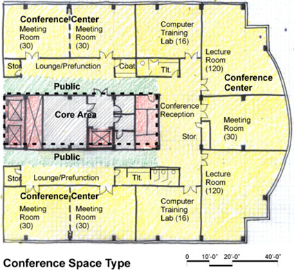
Example Construction Criteria
For GSA, the unit costs for firing range space types are based on the construction quality and design features in the following table . This information is based on GSA's benchmark interpretation and could be different for other owners.
Relevant Codes and Standards
The following agencies and organizations have developed codes and standards affecting the design of Conference/Classroom spaces. Note that the codes and standards are minimum requirements. Architects, engineers, and consultants should consider exceeding the applicable requirements whenever possible.
- ADA Standards for Accessible Design
- ICC IBC International Building Code
- PBS-P100 Facilities Standards for the Public Buildings Service, GSA
Additional Resources
Organizations and Associations
- U.S. Access Board
- Classroom Acoustics—A supplement to the ADA and ABA guidelines that addresses acoustics in classrooms.
Publications
- Accessible Information Exchange: Meeting on a Level Playing Field, by the U.S. Department of Justice, Civil Rights Division, Disability Rights Section.
- Architectural Graphic Standards, 12th Edition by The American Institute of Architects, Dennis J. Hall. New York, NY: John Wiley & Sons, Inc., 2016.
Confinement Facility
Models
| Title | View |
|---|---|
| Dynamic Prototype for Confinement Facility | View/Download > (3.6 MB) View/Download (55 MB) |
Consider Non-Quantifiable Benefits
Overview
Within This Page
The essential aspects of conducting a life-cycle cost analysis (LCCA) and determining the cost-effectiveness of any given construction alternative are the identification of all the relevant inputs and outputs and quantification, when possible, of these as costs and benefits to facilitate informed decision making. Costs can be more readily quantified than benefits because they normally have dollar amounts attached. Benefits are difficult because they often tend to have more intangibles. In analyses, benefits should be as important as costs and deserve to be brought to the attention of decision makers.

A courthouse building may be required to design its security to a Level 4 protection. The risk is reduced but costs are added to the project. Another possibility is the requirement to have a larger set-back for site security which can add to site costs initially but reduce security costs as a result. Issues such as these, need to be taken into consideration and planned for in the life-cycle cost analysis to determine their overall cost and benefit. Robert F. Stephens Courthouse Complex District Courthouse in Lexington, Kentucky. Image credit: Sherman Carter Barnhart Architects.
Other Quantifiable Benefits
Many investment decisions, especially in industrial applications, have a stated goal defined in terms of required or expected output (e.g. number of kilowatt-hours of electricity produced per year, number of aircraft overhauled per year). The goal is not always quantified, but it is often susceptible to quantification and thus provides a potential measure of benefits associated with the investment. A Benefit/Cost Ratio (BCR) may be determined when the output from the investment can be quantified and a uniform annual cost derived from the life-cycle cost analysis (LCCA). Using the examples provided, typical output of this type would be number of kilowatt-hours of electricity produced (benefit) or completed aircraft overhauls (benefit) per $1,000 (cost). These ratios may be compared for several different alternatives to assist in selection of the most cost-effective.
Non-Quantifiable Benefits
Despite best efforts to develop quantitative measures of benefits, there are situations that simply do not lend themselves to such an analysis. Certain projects may provide benefits such as improved quality of the working environment, preservation of cultural and historical resources, safety and security of the building occupants, and other similar qualitative advantages. Although they are most difficult to assess, these benefits should be documented and portrayed in a life-cycle cost analysis.


Owners of the West Bend Mutual Insurance credited the energy efficient strategies implemented in the new Headquarters Building, West Bend, IN for 99% reduction in personnel complaints about IAQ and 16% improvement in productivity.
In such instances, written and accurate descriptions of qualitative benefits must be done. This is the least preferred method of analyzing benefits due to its subjectivity and inherent lack of precision. However, under certain conditions, this method must suffice; and if the following guidelines are observed, qualitative statements can make a positive contribution to the analysis.
- Identify all benefits associated with each alternative under consideration. Give complete details.
- Identify the benefits common in kind but not to the same degree among the alternatives. Explain all differences in detail.
To formalize the inclusion of non-monetary costs or benefits in the decision-making process, the analytical hierarchy process (AHP) should be employed. AHP is one of a set of multi-attribute decision analysis (MADA) methods that consider non-monetary attributes (qualitative and quantitative) in addition to common economic evaluation measures when evaluating project alternatives. E 1765-16 Standard Practice for Applying Analytical Hierarchy Process (AHP) to Multiattribute Decision Analysis of Investments Related to Projects, Products, and Processes published by ASTM International presents a procedure for calculating and interpreting AHP scores of a project's total overall desirability when making building-related capital investment decisions.
Following these general guidelines will help to enhance the difficult task of documenting these intangibles that are measured in non-economic terms like aesthetics, safety, or morale, and enhance the value of benefit/cost analyses and make informed decision-making easier.
Quantifying Negative Aspects
It is also noted that in addition to benefits, information concerning negative aspects of alternatives, quantified where possible, should also be included to ensure the objectivity and completeness of the analysis. This information is important in decision making and possibly to the community at large; and may be a determining factor in deciding between possible investment alternatives.
Externalities
Externalities (also referred to as external effects or spillovers) are an important class of outputs that may be benefits or disadvantages. They are generally defined as outputs involuntarily received or imposed on a person or group because of an action by another and over which the recipient has no control. Air pollution is an example of an externality that is not a benefit. The recipients accrue potential health, aesthetic, and other disadvantages from a polluter for which they receive no compensation.
For most investment decisions (particularly with respect to the public sector), it is not necessary to analyze in depth externalities such as environmental impacts and community economic impacts as part of the life-cycle cost analysis. These aspects of alternatives being considered are usually treated in detail as part of the Environmental Impact Assessment/Environmental Impact Statement process or environmental documentation associated with local and state processes for addressing environmental impacts of construction projects. However, the mention of anticipated impacts (both quantified and qualitative) in life-cycle cost analysis documentation is appropriate.
Summary
There is no standard or recommended format prescribed for benefit analysis information. What is important is the content; and in the case of benefits, content is critical. No analysis is truly complete unless it addresses benefits attending all the alternatives under consideration.
Relevant Codes and Standards
- P100 Facilities Standard for the Public Buildings Service—Chapter 1.7 Life-Cycle Costing by the General Services Administration (GSA), 2015.
- E 1765-16 Standard Practice for Applying Analytical Hierarchy Process (AHP) to Multiattribute Decision Analysis of Investments Related to Projects, Products, and Processes published by ASTM International.
- Standards on Building Economics, 7th ed. ASTM, 2012. ISBN-13: 978-0803170322.
Additional Resources
Publications
- P-120 Project Estimating Requirements for the Public Buildings Service by the General Services Administration (GSA), 2007.
- National Performance Based Design Guide for Buildings by the National Institute of Building Sciences–High Performance Building Council.
- P-442 Economic Analysis Handbook by the by the Naval Facilities Engineering Command (NAVFAC), 2013.
Consolidated Communication Squadron Facility Requirements - Dynamic Prototypes (AFCEC)
Currently there is little design guidance in the development of communications facilities compared to other types of standard facilities. As a result, AFCEC directed Jacobs to collect the information gathered into an interim design document which could be used to provide some guidance for Consolidated Communications facilities currently planned as Sustainment, Renovation, and Modernization (SRM) or Military Construction (MILCON) projects, until such time as this prototype can be revisited and further developed into a full prototype.
Constructability Reviews
Introduction
Within This Page
Constructability reviews are routinely performed throughout the industry, but with mixed results. These varied results are driven by many factors, but the most predominant factors are the reviewer's experience level and amount of time allotted to complete the review. Construction management firms and general contractors regularly charge young project engineers with the task of performing constructability reviews simply because the more experienced executives do not have the time. Because design schedules and bidding periods are customarily short the time allotted for a constructability review is routinely very brief. This important task is sometimes limited to only two or three days. However, performing a constructability review requires an intimate knowledge of the project. The unfortunate reality is that when a mere few days is set aside for this important step the reviewer barely has enough time to attain an overview of the project, much less review and understand its intricacies.
Description
When allocated the task of performing a constructability review for the first time many look at the tremendous stack of drawings and specifications with the same unsettling thought; "Where do I start?" The answer to this question is actually quite simple, start at the bottom and work your way up. Go through the drawings in the same manner in which the project is built. A common procedural mistake made by inexperienced reviewers is starting on the first sheet of the drawings and simply flipping page by page looking for problems. Because construction projects are highly complex it is not realistic to expect that the problems will be clearly evident as you sift through the drawings. The most effective constructability reviews are completed by going through the construction process step by step. As you conceptually walk through the construction process you will inevitably discover details or written information that are either incorrect or missing from the documents. When these problems are noticed, you add them to the review comments. This is a basic and simple methodology, but it is also very time consuming. It is recommended that constructability reviews be performed in five common phases: 1) Structural, 2) Building Envelope, 3) Interior Architectural, 4) MEP, and finally 5) Sitework.
To help answer the question "Where do I start?" The top five rules for an effective constructability review are outlined below. This will help your team in producing quality constructability reviews that aid in the success of your projects.
The Top Five Rules for an Effective Constructability Review:
Build the Project; Don't focus solely on the problems. Only by taking the time to walk through the construction process step by tedious step will the problems be discovered. Avoid viewing a constructability review as an exercise in flipping through the construction documents with a focus on finding the problems, as the problems will not jump out at you.
Review the Interface of Various Systems. Whether it be interior, exterior, structural or MEP, problems are not discovered nearly as frequently within the body of a system as they are at the perimeter of a system where it interfaces with the various adjacent systems and trades.
Keep the Review of Preliminary Documents Constructive. When performing a constructability review on 50%, 75%, or even 90% documents, be cognizant that the design documents are not complete and avoid providing the design team an exhaustive list of things they already know aren't done. Preliminary reviews should focus on general design approaches, correcting items that have been completed and identifying the obscure, easy to miss, details.
Stay Focused on the Important Items. Before making a comment to the design team, ask yourself two questions. First, "Will this impact the cost, time, or quality of the project?" and secondly, "Will the contractor, or subcontractors, require an answer to this question in order to perform their work?" If the answer to either of these questions is yes, pose the comment. Otherwise, posing the comment will consume the design team's time that could be better spent directed to other issues.
Take the Time to Complete a Thorough Review. A thorough constructability review will take weeks, even months, but for every hour spent planning a project the hours saved down the road are exponential. Thorough reviews cannot always be complete and incorporated into the design documents in time for bid, but it is nonetheless important to address the problems early in the project.
There is a widespread misconception that constructability reviews must be completed in time for all solutions to be incorporated into the bidding documents. This belief is absolutely untrue. Incorporating all of the solutions prior to bidding would be optimal, but it is not a realistic expectation. Nor should this sequencing concern be a deterrent from performing thorough constructability reviews. It is still greatly beneficial when problems are identified and resolved shortly after the bidding phase. The sooner problems are identified and resolved, the greater success a project will have.
It is also important to keep in mind that constructability reviews benefit a project in more ways than one. For instance, a constructability review is an excellent exercise for the reviewer to learn and become knowledgeable of every facet and intricate detail of a project. This exercise is a tremendous benefit to the Project Superintendent in particular. It is also a more efficient method of solving problems than the alternative of issuing RFIs for each individual issue. And yet another advantage is that value engineering suggestions are a natural byproduct of this process.
A few of the fundamental benefits that are still realized when constructability reviews are completed shortly after the bidding phase include the following:
A reduction of change order issues resulting from re-work, as the problems will be identified and resolved before errant work is performed.
The luxury of time to review and negotiate change order pricing from the general contractor and subcontractors. When problems are discovered during the course of work time constraints often force you to hastily approve change order requests, even when you feel they might be excessive.
Avoidance of delays caused by problems discovered during the course of construction. The time it takes to examine a problem and devise a solution chronically slows, or even halts, progress.
Methodologies of completing thorough and comprehensive constructability reviews vary widely. For instance, they may be performed by the general contractor, construction manager, or even an independent firm. Furthermore, sometimes the review will be performed by a different person for each individual design discipline, and other times the entire review will be performed by a single person. All of the different methodologies comprise their own unique set of advantages and disadvantages.
For example, a constructability review performed by a different party for each design discipline will enable a person with specialized skills and deep experience in each respective field to be assigned. However, this approach will be deficient in regards to interdisciplinary coordination because the independent reviewers narrowly focus on their assigned set of drawings and specifications. Interdisciplinary coordination is tremendously important, as many change order issues originate from conflicts between the various design disciplines. Conversely, a review performed by a single person for the entire project will be highly effective with regard to interdisciplinary coordination, but may lack deep experience in each of the individual design fields.
A general contractor may directly employ 100 or more different companies for a construction project. There will be multiple bidders for each of these scopes of work, and the majority of these bidders will in turn receive bids from a variety of manufacturers, suppliers, and other companies as well. Once a project is completed, it is not uncommon for nearly 1,000 different companies to have been involved from the project's conception, through design, bidding, construction, and eventually completion. This emphasizes the importance of the design documents. The only truly efficient and effective means of conveying coordinated direction to all of these parties is via the design documents.
A notable misconception commonly held by design team members is that information they are unable to incorporate into the design documents prior to issuance for bidding can be quickly and simply added to the bid instructions. General contractors prepare and issue bid instructions to delineate the scope of work for each individual subcontractor. Although providing direction to the bidders via the bid instructions might appear equivalent to providing direction via the design documents, it can actually be quite confusing during construction. There are many reasons for this, but one is the status quo in the construction industry that all members of a project team must recognize is that subcontractors will thoroughly read the bid instructions during the bidding phase, but they are highly unlikely to ever review them again after being awarded a project. Because this is a standard operating procedure in the industry, it is actually much less efficient for the general contractor to issue direction in their bid instructions than it is to incorporate the direction into the design documents.
Again, it is a good management practice to perform a complete constructability review as early as possible, even though the review comments may not be incorporated into the design documents prior to bidding the project. It must be recognized and fully understood by all project team members that shortening or eliminating the constructability review process does not eliminate problems. Shortening or eliminating this crucial design step only delays discovery of the problems. It is always advantageous to identify and solve problems as early as possible. Identifying and solving problems early provides ample opportunity for resolution before delays are incurred and many times even before additional costs are incurred.
Application
Video providing an example of a Constructability Review. Play (4:18 min)
Video explaining the level of detail required at each of the various design stages, including the 50% DD, 100% DD, 50% CD and 90-100% CD milestones. Play (2:06 min)
Video discussing the Top 5 Barriers to completing a comprehensive Constructability Review. Play (4:58 min)
Video outlining the additional benefits of a Constructability Review. Play (4:10 min)
Emerging Issues
Design schedules always seem to be pressed for time, which is the result of two primary factors. The most obvious factor is that owners always want to move their projects forward as quickly as possible, so they pressure design teams into abbreviated design schedules. Architects frequently concede to this pressure. The second primary factor contributing to compressed design schedules is much less obvious than the first. It is human nature. People of all professions have a tendency to procrastinate in their duties. This is why design teams routinely accelerate their pace in the final weeks of the design phase, as opposed to progressing at a constant pace from start to finish. In the end, issuance of incomplete design documents is the recurrent and regrettable result of these two unfortunate factors.
Relevant Codes, Standards, and Guidelines
A constructability review must be performed by an experienced individual(s), which means an executive level person(s) must allocate a significant amount of their time for this task. In reality, finding executives with multiple weeks of available time is often deemed impossible. But problems are difficult to find and require an experienced set of eyes to identify. This means assigning young project engineers to this task is significantly less productive because the younger generation hasn't yet gained enough experience to know what to look for.
Employing a competent and reputable third party firm to perform a constructability review is an excellent management practice. Depending on the size and complexity of the project, a thorough constructability review can take weeks or even months to complete. Further, comprehensive constructability reviews cannot be performed until the design documents are near completion. This is the main reason that there never seems to be enough time for a thorough review. As a result, the constructability review process is often cut short.
Additional Resources
Web Resources
- Constructability Analysis and Planning, LLC (CAP)
- Educational Materials from Constructability Analysis and Planning, LLC
- Wikipedia entry on Constructability
- Constructability by The Institution of Professional Engineers New Zealand Incorporated (IPENZ), April 2008
- Strategic Value Solutions
Construction Phase Cost Management
Introduction
Within This Page
Construction Phase Cost Management comprises two major efforts:
- bid the project and select a general contractor;
- oversee/review costs from change orders and contractual claims.
A useful by-product of this stage is that cost data can be collected to inform future cost estimates. The cost manager should remain fully engaged in the project to assist the team in managing the project while also gathering data from bid analysis, the distribution of costs in the Schedule of Values, and the raw data used in change order submissions. This should be captured in a usable format for use in future budget-setting and detailed estimating, as depicted in the cost data loop below.
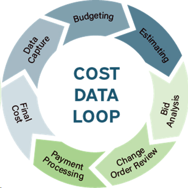
The Bid Process
The bidding process and the input from the cost manager can vary from very little to substantial, depending on the owner's capabilities and those of other consultants, e.g., an agency Construction Manager. At the very least the final cost estimate should be prepared in such a way as to facilitate comparison of the estimate with the bids received, typically by using the CSI MasterFormat (2020) work breakdown structure. Should a bid "bust" occur, this comparison can reveal what went wrong, for example all of the over-run may be in one trade, possibly indicating lack of competition or specifications that were written too restrictively.
It is also usually a worthwhile step to take the MasterFormat breakdown of the awarded bid and re-engineer that into a GSA UNIFORMAT II work breakdown structure, for use in future budgeting. While some MasterFormat divisions align with UNIFORMAT elements, e.g., HVAC, Plumbing or Electrical, most will need some analysis to properly assign to the UNIFORMAT element. But the information generated in this way, e.g., cost/SF of Superstructure or Exterior Closure, will enhance the accuracy of future budgets and early-phase cost estimates.
Change Order Evaluation
Cost management in the construction phase is critical to bringing a project in on budget. Cost issues from the point of signing a lump sum or GMP contract arise with the issuance of change orders, or contract modifications, against the contract. These are typically for one of the following reasons:
- initiated by the owner for a change the owner would like to make
- the result of unforeseen conditions such as below-ground obstructions or unexpected hidden structural issues
- the result of the contractor issuing a Request for Information (RFI), the answer to which results in a change to the contract drawings or specifications
- the result of a code interpretation/enforcement by the Authority Having Jurisdiction (AHJ) resulting in changes to scope or design detailing
- the result of an unexpected occurrence such as natural disaster, organized labor action, suspension of work, or unusual weather resulting in a delay to the project or other cost impact for which the contractor may be entitled to relief
In order to properly prepare an estimate for a change order, the estimator must understand the overall objective, i.e., to reach an agreement with the contractor that (in public sector work) is in the best interest of the government. The lowest possible price does not always meet this objective nor would a "generous" price if that price offers more payment than necessary to include sufficient incentive. The negotiation team must strive for some intermediate point, which is generally regarded as the lowest reasonable price - the amount at the bottom of the price range that the negotiator considers to be fair and reasonable.
To arrive at this price the negotiator must at least partially rely upon an independently prepared government estimate. This estimate must be based on a detailed analysis of the change in requirements and existing job conditions. For the most part, the estimate should be prepared similar to, and take into account, those same conditions and elements occurring in the contract, as each applies to the change order scope. In lieu of better data, the final government estimate for bid evaluation may be used for assistance.
Typically, an independent government estimate (IGE) must be prepared before the contract modification request is sent to the contractor. The same documents the contractor will use to prepare their proposal must be made available to the estimating team.
It is necessary to fully understand the scope change (by, for example, a meeting with the designer and owner and walking the project site) to then prepare an accurate quantity takeoff for each direct item of change (capturing adds and deducts). A cost is then applied to each of the direct items for labor (hours and rates for each trade involved), material and equipment, and sequentially apply appropriate overhead, profit, insurance and bond costs, all in accordance with the terms of the construction contract.
This formal, approved independent government estimate will be used to evaluate the contractor's proposal in determining reasonableness, and therefore must be prepared on a comparable and realistic basis. The estimator should therefore also become familiar with the modification and claim processes as outlined in the contract.
Preparation for Estimating
The estimator must review the change documents received and become thoroughly familiar with the scope and requirements of the changed work. This will perhaps entail detailed comparison, analysis and various discussions with the design team and owner to ensure understanding.
The estimator must determine the existing status of construction and how the changed work will fit into the construction schedule. This will require obtaining progress reports, schedules, and discussion with those closest to the work. This often requires a visit to the construction site, and emphasizes why on large projects it is useful to have a cost estimator on site.
The estimator should become fully aware of the contractor's existing methods, capabilities, and rates of accomplishment. The estimate should not arbitrarily include methods and capabilities different from the way in which the contractor is performing existing work. Unless the Contracting Officer is willing to direct the contractor to another method of performing work and assume the responsibility, the estimator should usually base the change on existing contractor operations for similar work. When work is anticipated to be subcontracted, prepare the estimate to include other indirect costs at the subcontractor level accordingly.
The estimator must obtain valid labor rates that the contractor is incurring and validate material and equipment costs using available commercial sources.
| LABOR RATES | Typically available from labor reports or from the contractor upon request. Productivity can be checked from sources such as R.S. Means, which includes crew sizes and typical output per hour for thousands of different activities. |
|---|---|
| MATERIAL PRICES | What the contractor is expected to pay from typical suppliers of that material, including any discounts. Quotes should be obtained if possible. |
| EQUIPMENT | The approach to determine equipment rates can be specified in the contract or as required by FAR 31.205-36. Quotes can typically be obtained, but the estimator should recognize the long-term aspect of most rentals (or ownership by the subcontractor), not just the daily or hourly rate for a specific change. |
The estimator, through the negotiator, should also attempt to agree tentatively with the contractor on scope and format before preparing the independent estimate. The intent of the agreement is not to influence the contents, price or independency of the Government estimate, but only to eliminate unnecessary wasted effort for both parties. The GSA P120 for example allows for the contractor's proposal to be used (with the costs deleted) as the starting point for the IGE.
Preparing the Estimate
After collecting and analyzing all the information, the estimator must decide upon the presentation format, absent a prior agreement and discussion. Unless otherwise agreed, the format for the estimate will be CSI MasterFormat 2020 with a level of detail as per the available detail on the Construction Documents. General guidance for the calculation of direct costs can be provided as follows:
| ADDITIONAL WORK | CHANGED WORK | DELETED WORK |
|---|---|---|
|
|
|
Impact considerations of cost on the remaining unchanged work will be discussed forward. Clearly and adequately describe and identify impact related costs as a separate part to each estimate.

Prepare an estimate for a modification in at least as much detail as the bidding estimate. Many instances will require even more detail in order to negotiate the lowest reasonable price. Each modification estimate should include a general summary sheet relating the major categories of cost of the modification, both for decreases and increases. Include the construction plan, descriptions, utilization schedules, and discussion sheets that would aid in understanding and support the estimator's judgments.
The result will generally provide an IGE that can be defended and utilized as a firm basis for negotiation. Any guidance on composition for the contractor is equally applicable to the breakdown required for the government estimate. The government estimate should not rely on past generalized rates and settlements unless actually appropriate to that specific modification.
Estimators should base the estimate on the most dependable information available. The most reliable source is the data actually collected and experienced from the project. Time studies, periodic field visits, the project schedule of values, and log records can provide this data.
Previous modification results as one source of feedback can also provide valuable data. Experienced cost data is often available from past audit reports on other modifications. The contract should also be referenced for the "rules of engagement" i.e. those contract provisions that govern allowable mark-ups for overhead and profit. These rules should be reviewed by the parties and clarified as to their intent at the outset of the project.
The estimate must be prepared in a timely manner. Procurement requirements stress the importance of settlement prior to commencing the work. The estimator must not be the initiator of a cost-plus settlement as a result of delay in preparation. On the other hand, the estimate should not be based on pure judgment when actual data is obtainable. Therefore, the estimator should immediately proceed to obtain the necessary data for the modification estimate and notify the appropriate contract administration specialist of the earliest date that the estimate can be completed. It is generally understood that the larger and more complex the change, the longer the time requirement for the initial preparation of dependable estimate.
Impact Cost Considerations
When a modification is directed, the settlement of that modification includes not only the cost and time change of the work directly affected but also the cost and time impact on the unchanged work. The impact portion on unchanged work of a modification is very difficult to determine. The scope of impact can be very broad, intangible, and susceptible to a large variety of situations.
By far the greatest portion of impact costs results from acceleration or delays. In general, when delay effect can be minimized, impact costs are reduced. It is typically necessary that the claim be reviewed for validity by a team involving all-around expertise.
Impact costs are generally first presented by the contractor as "claimed" impact cost as part of the proposal. The support for such "claimed" cost should also be obtained and include narrative, calculations, and planned rescheduling. To determine the extent of the impact, the existing Critical Path Method (CPM) schedule furnished by the contractor must be developed to reflect actual construction as accurately as possible. The modification work must be superimposed upon the original schedule in such a manner to minimize delay under the given requirements. The revised schedule must then be thoroughly reviewed relative to the existing job plan, particularly as to impacts to the critical path.
This comparative review should indicate those areas that have been affected by the modification. Once identified, each construction task must be analyzed for impact and estimated judgmentally considering the influences caused by the change. Each impact cost claimed should be classified as either factual or judgmental.
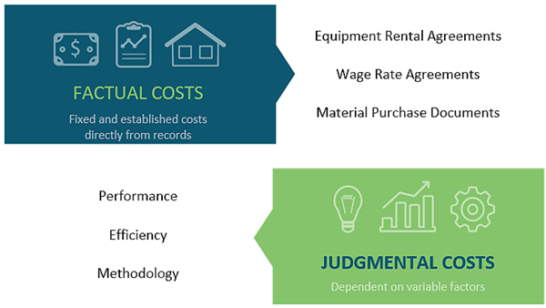
Once an item has been determined to be valid as a factual impact, the item cost may be directly calculated. The amount of cost change is either stated on the certification document or can be determined from the scheduled time change of the construction progress plan.
Judgmental costs must be negotiated and be based upon experienced judgments. Judgment or costs can be challenged but cannot be found erroneous if based on reasonable judgments of the conditions. Since judgmental factors appear in the Government estimate and the contractor's proposal, results of negotiations often depend on credibility and clarity of support documentation.
| FACTUAL COSTS | JUDGMENT COSTS |
|---|---|
| Material price escalation | Change of efficiency |
| Labor wage escalation | Loss of labor efficiency |
| Equipment rate changes | Disruption to orderly existing processes and procedures |
| Materials and equipment storage | Inefficiency from rework |
| Equipment rental/use | Loss of efficiency from rescheduled manpower |
| Labor cost and subsistence | Impact to morale |
| Utilization of overhead personnel, materials, and utilities | Inefficiency incurred from resubmittals | Overhead and project office services | Impact of transferred manpower/expertise |
When each impacted activity can be analyzed for cost separately, the estimate of impact should be prepared accordingly. However, sometimes the impact items are so interrelated that it is best to develop a detailed plan for accomplishing the total remaining revised contract work.
Each remaining item in this plan would be costed at the productivity and rate in effect at the time the work is to be accomplished and the cost incurred. The same scope of work under the original plan would also be separately costed at the productivity and rates in effect at the originally scheduled time. The net difference from the totals of these two estimates yields the cost of impact.
Whatever the method used, those impacts determined valid must be included and costed by the most accurate method available. The estimator should avoid including questionable impact costs in the initial government estimate unless each has been found to be justifiable.
Note that earned value analysis is a useful tool to determine at any given point in time the financial status of the project and to forecast the likely outcome.
Support for Negotiations
Once the government estimate for the modification has been completed, approved, and delivered to the Contracting Officer or his/her authorized representative, the estimator should continue to support the negotiations. This support is entirely dependent upon the desires of the negotiator. The estimator must become thoroughly familiar with negotiating requirements and techniques before the estimator participates as part of a negotiating team.
Whenever feasible, the estimator should review the contractor's proposal and furnish the negotiator with the resulting analysis. The estimator must review many of the costs presented in the contractor's proposal breakdown for accuracy, reasonableness, and allowability. Of those costs found allowable (see FAR 31.2), each must further be reviewed for applicability for that portion relevant to the particular project. The government should expect to pay for all reasonable costs anticipated to be incurred by the contractor.
Revision of the Government Estimate
As a result of an error, different conditions, or additional information, the government estimate may require revision. It is permissible for government estimates for modifications to be revised either by supplementary sheets or by actually changing the contents of the original estimate pages. The method used will be determined by the extent of the revision and the format utilized. Whichever the method, all revisions to the estimate must be clearly indicated, dated, justified, and approved by the appropriate authority. The appropriate authority is usually considered to be the original estimate approving individual or the individual having authority to approve the modification itself.
Contractual Claims
Every construction contract contains provisions for dealing with "claims" for additional costs or time extensions as a result of the failure of one party to the contract to perform one of its obligations. These typically are time-related and arise when the general contractor forms the opinion that some act or lack of action has caused him a delay on the project. This is a very complex subject and contracts vary in how claims are dealt with, however in essence the delay claimed must be on the critical path, must be notified in writing within a given time period of the delay occurring, and must be the result of the owner or someone acting for the owner (e.g. the architect) failing to fulfill a contractual obligation for the claim to succeed. A claim can be rejected or at least diluted if the contractor is also behind in other areas which are causing a delay in the project (referred to as a concurrent delay) and there are myriad other issues which come into play. It is often necessary to bring in a claims and scheduling expert to sort through all the paperwork and establish the root causes of a delay and the true cost, if any, to the general contractor.
Additional Resources
Associations
- American Association of Cost Engineering International
- Construction Management Association of America
- Project Management Institute
- Royal Institution of Chartered Surveyors
Publications
- Architect's Essentials of Cost Management by Michael Dell'Isola. New York, NY: John Wiley & Sons, Inc., 2002.
- Construction Change Orders: Impact, Avoidance, and Documentation by James J. O'Brien. New York, NY: McGraw-Hill, 2002.
- Construction Claims: Prevention and Resolution, 3rd Edition by Robert A. Rubin, Virginia Fairweather, Sammie D. Guy. New York, NY: John Wiley & Sons, Inc., 1999.
- Construction Contracts: Law and Management by J. R. Murdoch, Will Hughes, John Murdoch. New York, NY: Spon Press, 2000.
- Smith, Currie & Hancock's LLP's Common Sense Construction Law: A Practical Guide for the Construction Professional, 2nd Edition by Robert B. Ansley, Thomas J. Kelleher, Anthony D. Lehman. New York, NY: John Wiley & Sons, Inc., 2004.
Construction Waste Management
Introduction
Within This Page
Responsible management of waste is an essential aspect of sustainable building. In this context, managing waste means eliminating waste where possible; minimizing waste where feasible; and reusing materials which might otherwise become waste. Solid waste management practices have identified the reduction, recycling, and reuse of wastes as essential for sustainable management of resources.
Most construction and demolition waste currently generated in the U.S. is lawfully destined for disposal in landfills regulated under Code of Federal Regulations (CFR) 40, subtitles D and C. In some areas all or part of construction and demolition waste stream is unlawfully deposited on land, or in natural drainages including water, contrary to regulations to protect human health, commerce and the environment. Businesses and citizens of the U.S. legally dispose of millions of tons of building-related waste in solid waste landfills each year. Increasingly, significant volumes of construction related waste are removed from the waste stream through a process called diversion. Diverted materials are sorted for subsequent recycling, and in some cases reused. Volumes of building-related waste generated are significantly influenced by macroeconomic conditions affecting construction, societal consumption trends, and natural and anthropogenic hazards. In recent years, construction industry awareness of disposal and reuse issues has been recognized to reduce volumes of construction and demolition waste disposed in landfills.

C&D landfill cell
Many opportunities exist for the beneficial reduction and recovery of materials that would otherwise be destined for disposal as waste. Construction industry professionals and building owners can educate and be educated about issues such as beneficial reuse, effective strategies for identification and separation of wastes, and economically viable means of promoting environmentally and socially appropriate means of reducing total waste disposed. Organizations and governments can assume stewardship responsibilities for the orderly, reasonable, and effective disposal of building-related waste, promotion of public and industry awareness of disposal issues, and providing stable business-friendly environments for collecting, processing, and repurposing of wastes. Businesses can create value through the return of wastes back to manufacturing processes, promoting and seeking out opportunities for incorporation of recycled materials into products, and prioritizing reduction of building-related wastes through efficient jobsite practices.
Description
Effective management of building-related waste requires coordinated action of governmental, business, and professional groups and their activities. Several non-governmental organizations and societies in the US promote coordinated action, and have identified best management practices in the interest of public health and welfare (see resources.) Absent coordinated regulations, realistic business opportunities, and the commitment of design and construction professionals and their clients for continual improvement of industry practices, consistent and stable markets for recovered materials cannot be achieved or sustained.
Management of building-related waste is expensive and often presents unintended consequences. However, common sense suggests that failure to reduce, reuse and recycle societal wastes is unsustainable. It stands to reason that efficient and effective elimination and minimization of waste, and reuse of materials are essential aspects of design and construction activity. Creativity, persistence, knowledge of available markets and businesses, and understanding of applicable regulations are important skills for design and construction professionals.
Eliminating Waste
Some waste generated in the process of construction can be eliminated. For example, durable modular metal form systems for use in concrete construction may be selected on the basis of being readily demountable and reusable on other projects, thus eliminating wood waste associated with formwork fabricated of plywood and dimensional lumber. Elimination of waste can be beneficial to reduce impacts on human health and the environment.
Minimizing Waste
Some building-related waste can be minimized. For example, construction products can be selected on the basis of its being designed and manufactured to be shipped with minimal packaging. Also consider that selection and use of recyclable materials and products offers potential to minimize waste.
Reusing Materials

Commingled C&D waste in roll-off
Some materials can be reused. For example, doors and windows in good, resalable condition might substitute for new products, or be donated and or sold for use on another project—a form of beneficial reuse.
Materials and products which cannot efficiently and effectively be eliminated, minimized or reused ultimately are collected, and unless managed, will probably be disposed at the lowest cost. In many areas of the country, disposal fees at solid waste landfills are substantially higher than the cost of separation and recovery, including the disposal cost for residues.
A. Federal Regulations
In the United States, the Resource Conservation and Recovery Act (RCRA) defines the subset of solid waste known as hazardous waste. The term "hazardous" was intended to designate wastes that present a serious risk to human health and the environment when mismanaged. Several components encountered as part of construction and demolition materials operations are RCRA hazardous wastes and therefore processes must meet all of the regulatory management requirements for hazardous waste. Note that hazardous most hazardous components encountered with construction and demolition materials operations are identified by respective characteristics, rather than listing. For example, discarded paints and solvents would have ignitability characteristics; batteries would have corrosivity characteristics.
In Canada, the Canadian Environmental Protection Act, 1999 (CEPA 1999) is the primary element of the legislative framework for protecting the Canadian environment and human health. In Canada, each level of government has powers to protect the environment. Collection, diversion, and disposal operations are the responsibility of municipal governments, while the approval, licensing and monitoring of operations are the responsibility of the provinces and territories.
B. Management
Most construction and demolition debris is generated at the project level and therefore subject to laws and regulations by local, state, provincial, and federal laws. Construction and demolition debris is defined at the state level in the United States, and at the provincial level in Canada. Check local, state, and provincial regulations to verify correct interpretation of the law.
Local practices in the management and disposal of construction and demolition wastes often are shaped by the availability of suitable disposal sites, economic conditions, societal priorities, availability of markets for recycling and reuse, transportation options, and the capabilities of local workforces and construction businesses to adapt demolition processes for management of wastes.
Management of construction and demolition wastes is addressed at project, organization, and disposition levels.
Project Level—Enhancing project value and performance
The project level encompasses the work of a specific project or projects, and is administered by the project team, often led by the architect or engineer during the design phase. The project level requirements are often communicated through project specifications, and contract provisions. Green building certification programs, notably LEED, include protocols, measurement and verification targets, and documentation that may be helpful to ensure project goals are achieved.
Organization Level—Stewardship of corporate values and priorities
The organization level encompasses the management of wastes identified at the project level, and includes the business practices and priorities of building owners and general contractors. The organization level provisions are often communicated through corporate reports, policy statements, and work plans. Performance measured against corporate targets for diversion, reduction in greenhouse gas emissions, and sustainability metrics are increasingly being recognized in industry programs recognizing corporate green building practices. Organizations can work with vendors responsible at the disposition level to ensure that business practices and operation of segregation, sorting, transporting and final disposition of wastes meet or exceed corporate expectations.
Disposition Level—Management of diversion and disposal
The disposition level encompasses the segregation, sorting, handling, transporting and final disposition of wastes, and is administered by the businesses and agencies responsible for disposal under contract or agreement, under licenses, and in accordance with all laws and regulations. Communication is often provided in the form of written diversion reports tabulating the amounts of materials accepted, diverted, and disposed, and the locations of final disposition of the materials received. Service providers at the disposition level can work with building owners and general contractors for project-specific approaches to managing waste, including custom diversion plans tailored to the project opportunities.
C. Definitions
Alternative Daily Cover (ADC): Material having no value in reuse, although employed for beneficial use as a supplement to soil in the practice of applying earth cover over active portions of managed municipal solid waste landfills, thus covering the day's waste, and with the effect of reducing nuisance odor and exploitation by animals, birds and insects.
Beneficial Use: An assertion of right to enjoy the benefits of specific property. Industry best practices promote inspection and evaluation of materials and products proposed for reuse to be certain hazards are mitigated, for example: window assemblies which include caulking containing PCB compounds; friable asbestos containing products; light fixture ballasts; etc generally pose risks to human and environmental well-being.
Canadian Environmental Protection Act, 1999 (CEPA 1999): CEPA consolidated selected provisions and laws administered by Environment Canada, and provides a framework for the management and control of toxic substances at each stage of their life cycle from development and manufacturing/importation through transportation, distribution and use, storage and ultimate disposal as waste.
Commingle: A term referring to the practice of placing unrelated materials together in a single container, usually for benefits of convenience and speed, but presenting challenges for subsequent recovery and diversion.
Construction Waste: Waste generated by construction activities, such as scrap, damaged or spoiled materials, temporary and expendable construction materials, and aids that are not included in the finished project, packaging materials, and waste generated by the workforce.
Demolition Debris: Waste generated from the process of intentional dismantling all or portions of a building, and clearing of buildings and contents destroyed or damaged as a result of natural or anthropogenic hazards. Demolition debris often contains constituents regulated in the US as hazardous waste under RCRA Subtitle C, 40 CFR.
Disposal: Depositing waste in a solid waste disposal facility, usually a managed landfill, regulated in the US under RCRA Subtitle D, or in the case of hazardous waste, under Subtitle C, 40 CFR.
Diversion: The practice of diverting waste from disposal in a landfill, by means of eliminating or minimizing waste, or reuse of materials.
Diversion Report: A written assertion by a material recovery facility operator identifying constituent materials diverted from disposal, usually including summary tabulations of materials, weight in short-ton units (NIST), and percentages.
Industrial Waste Stabilizer (IWS): Material having no value in reuse, although employed for beneficial use in stabilization of industrial waste in landfills.
Landclearing Debris: Waste generated from the process of clearing land, including preparing building sites for construction, generally consisting of vegetation, soil, rocks, and constituent matter.
LEED: An internationally recognized green building certification system, providing third-party verification that a building or community was designed and built using strategies intended to improve performance in metrics such as energy savings, water efficiency, CO2 emissions reduction, improved indoor environmental quality, and stewardship of resources and sensitivity to their impacts.
Organics: Vegetation, soils, and constituent matter excluding rocks, and being both carbon- and nitrogen-rich, and completely biodegradable to carbon dioxide, water and biomass through the action of micro-organisms under normal environmental conditions.
Recycling: Introducing a material into some process for remanufacture into a new product, which may be the same or similar product or a completely different type of product.
Residue: Waste which is economically impractical to recover for reuse or to divert from disposal.
Resource Conservation and Recovery Act (RCRA): The principal Federal law in the United States, enacted in 1976 and amending the Solid Waste Disposal Act of 1965, with the intent of governing the disposal of solid waste and hazardous waste, and codified in Title 40 CFR. Construction and demolition debris are regulated under Subtitle D: Non-hazardous solid wastes. Hazardous wastes are regulated under Subtitle C, known as the 'cradle to grave' system with stringent bookkeeping and reporting requirements. RCRA authorizes states to carry out many of the federal regulations through their own state laws, with such laws subject to approval by the EPA.
Reuse: The subsequent use of a material, product, or component upon salvage.
Salvage: Recovery of components, products, or materials for the purpose of reusing them for the same or similar purposes as their original use.
Sortline (or Pickline): An item of industrial recycling equipment featuring a conveyor belt and several stations for workers to rapidly sort and segregate waste, usually part of a material recovery facility.
Source Separation: A term referring to the practice of administering and implementing a management strategy to identify and segregate unrelated waste at the first opportunity, thus simplifying subsequent processes for recovery of materials and diversion, but presenting challenges for management of space on the jobsite, training and supervision, and inefficiencies associated with hauling.
D. Construction and Demolition Wastes
Wastes encountered constitute all the materials and products incorporated into the built environment over a period of decades or in some areas over centuries. Include in that list earth, pavement, and organic plant materials. Assessment of wastes to be encountered on projects is an important first step in developing a construction and demolition waste management plan at the project level.
Industrial hygienists perform waste characterization studies and identify components which present known risks to human health and the environment. Specialty contractors provide comprehensive services for identification, verification, removal, handling and disposal of known and suspect hazardous and dangerous materials in accordance with applicable regulations.
Materials and products presenting known risk:
- Hazardous wastes (listed, characteristic and universal types identified by US EPA)
- Asbestos-containing materials (friable)
- Asbestos-containing materials (non-friable)
- Lead-containing materials
- Products containing polychlorinated biphenyls (PCBs)
- Solvents, chemicals, petroleum-derived products
- Dust
- Fluorescent and compact fluorescent lamps
- Electronics
- Medical waste
- Materials contaminated with waste
Materials and products typically benign:
- Woody and plant materials
- Concrete
- Gravel, aggregate, stone and rock
- Masonry and rubble
- Metals (ferrous and non-ferrous)
- Wood
- Plastic
- Glass
- Doors and windows
- Asphaltic roofing
- Gypsum board
- Carpet and pad
- Cardboard and paper
- Plumbing fixtures
- Lighting fixtures
E. Best Management Practices
How waste management, or diversion, is accomplished, and to what extent, depends on specific project requirements and conditions. Several issues contribute to an overall waste diversion strategy.
F. Process
Jobsite Sorting
Efficient identification and sorting of materials is an important factor in managing the economic viability of diverting construction debris from disposal. Jobsite protocols are identified in contracts and subcontracts, and implemented at the project level by superintendents and project managers. Superintendents and project managers utilize project specifications prepared by architects and engineers for information on diversion target rates, and general performance requirements. Building owners and contractors may have corporate guidelines and policies which improve upon project specific requirements. Materials may be sorted into a number of containers provided by service companies that specialize in management of specific types of waste at the jobsite. Generally the least number of containers is desirable both to keep container volumes high to reduce transportation trips and costs, and to keep the jobsite clear of obstructions.
Collection and Hauling
Containers containing construction and demolition waste are collected and transported to diversion facilities via truck. Light and medium duty trucks are most commonly used for this purpose in the US and Canada. Trucks and containers of various types are mated to allow for maneuverability and modular interoperability.
Tipping
Identification of loads on arrival at construction and demolition debris diversion facilities is an important step in ensuring materials are appropriately handled. Facility management plans typically describe materials that can be accepted. Loads which contain materials that are not accepted may be turned away, in which case the materials likely will be disposed in a sanitary landfill. The four hazardous waste characteristics are: corrosivity, ignitability, reactivity, and toxicity.
Picking
Materials are typically handled with equipment specifically designed to support heavy loads and resist abrasion. Materials are discharged from containers onto a tipping or receiving floor, usually beneath a roof cover or inside an industrial building. Once on the floor, a wheel loader operator will stockpile materials which will be picked through with a hydraulic excavator or a grapple. Materials such as steel reinforcing bar, carpeting, large pieces of wood, concrete and materials with dimensions greater than 3 feet are usually picked before the sorting process can begin in earnest.
Sorting
Sorting generally involves loading materials onto an inclined metal belt—a chainbelt—and passed across a manual sortline consisting of a flexible rubber belt and integral sort stations providing a place for several workers to stand, usually opposite from one another down the length of the belt. Materials are identified, grabbed, and deposited in vertical openings at each sort station. The effectiveness of the manual sort line is largely determined by the performance of the picking operation which precedes it; for example large materials on the belt can be difficult to manage and or obstruct recoverable materials passing by on the belt beneath.
Containerization and Transport
Picked and sorted materials are deposited by means of equipment and manual labor into industrial containers of various types. Combination compactor-balers are used in some applications to produce dense bales of materials which are then loaded into intermodal shipping containers for transport. Heavy interstate trucks are an important part of the transportation system. Containers of all types are destined for transport locally, regionally, nationally and internationally via road, rail, or barge via intermodal facilities such as railyards and ports. Once containerized, recyclable materials are commoditized and traded in the global marketplace.
Diversion or Disposal
Diverted materials are destined for incorporation in new products as recycled material, or are processed for reuse. Materials destined for disposal in landfills include refuse, materials contaminated with waste or which have been ruined, and materials for which markets do not exist.
G. Prevalence of Common Materials
Constituent proportions of materials culled and sorted in the construction and demolition waste stream shows a high degree of correlation with local priorities and economic trends at a given time. For example, communities with a preponderance of 19th century buildings and undergoing gentrification tend to have a larger proportion of masonry waste as contrasted with a suburban neighborhood undergoing renovations and additions to lightly-built wood frame structures. Diversion performance over a two year period (2009-10) processing 20,000 tons of construction and demolition waste generated in an urban area in the US (2010) demonstrates the following proportions:
Ferrous and non-ferrous metal—9%: Ferrous and non-ferrous metals are among the most valuable materials in the construction and demolition waste stream. Ferrous metals are extracted from bits of concrete with hydraulic excavating equipment, and deposited into containers. Small bits of ferrous metal are collected with electromagnets positioned over the sortline belt, and grabbed manually. Non-ferrous metals, predominantly aluminum, are collected with a reverse magnet known as an Eddy current separator, and grabbed manually. Metals consistently demonstrate the highest diversion rate of all the recoverable materials.
Cardboard and Paper—3%: Cardboard and paper recovered from construction and demolition debris waste have value as recyclable materials, however are generally of a lower grade than cardboard collected at curbside, as a result of consequential exposure to water, and contamination with dusts. Cardboard and paper are usually baled for economical transport to paper and cardboard mills.
Plastic—1%: Post-consumer plastics 1 (PET) & 2 (HDPE) are valuable commodities. Plastics 3 through 7 are generally recyclable but have less value. Generally plastics are not recycled into material of the same type and grade (downcycled). PET is readily converted into a wide variety of products. HDPE is downcycled into plastic lumber, trash receptacles, etc. Plastic film is a nuisance material that impedes efficient picking and sorting of all other materials. When prices of the recycled commodities are low, plastic materials may be exported and or combusted for their energy-producing potential. Plastic may be granulated or chopped into flakes and placed in industrial tote bags for transport.
01: Polyethylene terephthalate (PET) 02: High-density polyethylene (HDPE) 03: Polyvinyl chloride (PVC) 04: Low-density polyethylene (PE-LD) 05: Polypropylene (PP) 06: Polystyrene (PS) 07: Other (O)
Wood—30%: Wood is a predominant material for waste streams in North America, and is highly useful in a wide variety of industrial processes including manufacturing of high recycled content products. Wood is a valuable commodity and merits diversion. Wood waste can also be processed to make feedstock for biomass and combined heat and power plants.
Concrete—5%: Concrete is crushed, and embedded metals removed for recycling. Rock and cement pieces are crushed, screened and separated to produce useful aggregates of various dimensions. It is advisable to characterize painted concrete and concrete which has been contaminated with wastes before recycling.
Industrial Waste Stabilizer (IWS)—25%: IWS is a form of diversion or disposal in some parts of North America whereby materials with no economic value between 0.75 to 8 inches dimension are disposed in industrial waste landfills, to promote physical stabilization of the landfill.
Gravel, aggregate and fines—20%: Gravel, small stones, concrete chips and similar materials can be diverted from disposal with trommel screens positioned before the inclined chain belt, or debris roll screens positioned at the end of the sortline belt.
Disposal as refuse—5%: Refuse passes off the end of the sortline belt. Generally the proportion of refuse should be less than 10%.
Window glass—0.15%: Window glass is a nuisance material with a nominal value as a recyclable commodity. Its relatively high weight per volume is a factor in restricting economical transport. Window glass usually ends up in a landfill unless a recycler is located in the vicinity of the diversion facility.
Carpeting—0.85%: Diversion of carpet from the landfill is very significant in reducing greenhouse gas emissions associated with manufacture of new carpet. Carpeting is a nuisance material in the picking and sorting process, complicating the efficient recovery of materials with higher values. Carpeting is generally picked from stockpiles on the receiving floor, and deposited in containers for transport to manufacturers who can make use of the fiber materials to make new products.
Drywall—3%: Drywall is 100% recyclable. Gypsum is a nuisance material in picking and sorting operations, producing dust which discomforts labor, and reduces the value of recyclable materials through contamination. Gypsum may be incorporated into new drywall, or used as a soil amendment.
Asphalt roofing—5%: Asphalt roofing shingles may be ground, sized and graded for remelting in asphalt paving applications, road base, new roofing, and fuel oil. Asphalt shingles consist of felt saturated with asphalt, and with mineral stabilizers and rock granules added. Asphalt constitutes 20 to 35% of the product weight. Contaminants including metal items and any wood waste must be removed.
Usually destined for other facilities: Appliances, equipment, tires, electronics, plumbing fixtures, asphalt, non-ferrous materials including copper, brass and stainless steel, landclearing debris. These materials may have value in secondary markets when one is available, or require special handling and management such as is the case with tires and appliances. Tires must be shredded in order to reduce the likelihood of being disposed of in unmanaged tire landfills. Appliances may contain refrigerants and other materials which pose environmental hazards.
Usually destined for reuse: Doors, windows, hardware: these materials often have value in a secondary market when one is available.
Nuisance materials: Sheet plastic, carpeting, drywall each require specific handling procedures to promote efficient handling of the rest of the waste stream. When commingled with other construction and demolition waste, these materials are generally picked with hydraulic excavating equipment or grapples—a costly and time-consuming process - before the bulk of waste is loaded onto a chainbelt and passed across a manual sort line.
1. Waste Management Planning
Waste management should be an integral part of a project's development. Each of the principal project participants—the Owner, their Architectural and Engineering (A/E) services (or Construction Management consultant), the Contractor, and Subcontractors—will engage in waste management to some degree throughout the project. Initially, the Owner and their A/E must establish waste reduction goals and define what levels of diversion are achievable and reasonable under the project's conditions and as required by:
- State and local regulations
- U.S. EPA
- State statutes or
- Green Building Rating program requirements.
2. Facility Design
The Contractor is responsible for the means, methods, techniques, sequences, and procedures of construction, which include waste disposal methods. However, the A/E's design team can contribute to waste reduction in several ways. These include:
Observe Value Engineering principals. Perform multiple functions with one material rather than requiring multiple materials to perform one function. Design to optimize systems' and components' use. Avoid extraneous materials that do not contribute to function.
Be efficient in area and volume. If less material is required by the design, less waste is generated at the jobsite.
Observe standard material and product dimensions. Locate features "on module" to the extent possible to reduce cutting and special fitting, which creates scrap.
Where possible, select construction systems that do not require temporary support, shoring, construction aids, or other materials that will be disposed of as debris during the project.
Where possible, select materials that do not rely on adhesives, which require containers and create residue and packaging waste. Furthermore, adhesives inhibit salvage and recycling at the end of the component's or building's life.
Where possible, reduce requirements for applied finishes, laminates, coatings, adhesives, and the associated scrap, packaging, and waste. Select materials with integral finishes.
Where possible, avoid materials which are sensitive to damage, contamination, environmental exposure, or spoilage on-site, which increase the potential for jobsite waste.
3. Construction Contract Requirements
The Owner and their A/E (or CM consultant) must determine how their waste management requirements will be represented in the contract documents and incorporated into the project. Several provisions are relevant to the project's overall waste reduction performance.
- There are essentially three ways to represent waste reduction requirements in the contract documents.
- Describe the waste reduction goals and rely on the Contractor's own initiative to achieve them. This may be effective if the Owner and Contractor share a good working relationship, and encouraging the Contractor is sufficient for them to "do the right thing."
- Specify definitive minimum waste and debris diversion criteria. This is commonly incorporated into the Demolition specification as a numerical criterion, such as "divert from landfill disposal a minimum of 75% of the non-hazardous construction waste generated at the jobsite."
- Develop incentives to reward the Contractor. This may be implemented as an award-type incentive based on the diversion rate, or by including Options in the Bid Schedule for each of several ranges of diversion rates. Note that simply requiring a specific LEED rating does not guarantee credit MR 2.1 or 2.2 (50%, and an additional 25% C&D waste diversion, respectively) will be attained. If the Owner, and their A/E or CM consultant desire to rely only on LEED as their requirement for environmental performance, they can still specify that MR-2.1 or MR-2.2 are mandatory for the project.
- Require the Contractor to submit a C&D Waste Management Plan. Typically, the Plan includes the following:
- Name of individual(s) responsible for waste prevention and management.
- Actions that will be taken to reduce solid waste generation.
- Description of the regular meetings to address waste management.
- Description of the specific approaches to be used in recycling/reuse.
- Waste characterization; estimated material types and quantities.
- Name of landfill and the estimated costs, assuming no salvage or recycling.
- Identification of local and regional reuse programs.
- List of specific waste materials to be salvaged and recycled.
- Estimated percentage of waste diverted by this Plan.
- Recycling facilities to be used.
- Identification of materials that cannot be recycled or reused.
- Description of the means by which any materials to be recycled or salvaged will be protected from contamination.
- Description of the means of collection and transportation of the recycled and salvaged materials.
- Anticipated net cost or savings. Some examples of C&D Waste Management Requirements and Plans are provided in Additional Resources, below.
Require the Contractor to document their actual waste diversion performance throughout the project. The Waste Management Plan, therefore, should also include progress reporting procedures to record actual diversion and cost corresponding to each diversion and cost estimate.
As the accepted Plan is a part of the contract document, it should be incorporated into the Contractor's Quality Control and Owner's Quality Assurance processes. Some public Owners go so far as to specify that progress payments will not be approved until updated actual diversion performance reports are submitted.
Vest title to debris and waste materials to the Contractor, and allow the Contractor to accrue the economic benefits. These include cost avoidance through reduced debris tipping expenses, revenues from salvaged and recycled materials, and cost avoidance by using materials taken from the jobsite back into the project.
4. Jobsite Waste Reduction
There are a variety of ways a Contractor can divert construction waste or demolition debris at the jobsite. The following general practices are common:
- Up to 10-12% of a project's construction waste stream can be cardboard alone. While protecting new materials is necessary, the Contractor can direct their subcontractors and suppliers to reduce extraneous packing and packing.
- Purchase materials in bulk where possible. Avoid individual packaging for volume purchases.
- Use returnable containers and packing materials
- Reuse non-returnable containers on the jobsite to the maximum extent possible. Develop one-hundred-and-one-uses for plastic barrels, buckets, and tubs.
- Give away non-returnable containers. Contact local and community organizations (schools, youth groups, community service groups, Habitat for Humanity, others similar).
Use scrap in lieu of cutting full new materials. Direct subcontractors and trades to collect and keep scrap at cutting and fabricating locations. Collect paints and liquids from almost-empty containers; avoid disposing of useable materials simply because there is not enough in one container to finish a job.
For materials that are heated, mixed, exposed to environmental conditions, or otherwise subject to spoilage, limit preparation of these materials to quantities which can be installed within their expiration times. Working in smaller batches will reduce the necessity to throw out expired or spoiled materials. Ensure volatile materials, and materials that degrade when exposed to heat, cold, or moisture are protected from spoilage and are not wasted.
Recycle damaged components, products, and materials, or disassemble them into their constituent materials for recycling.
Establish a return or buy-back arrangement with suppliers. Alternatively, unused, or used but serviceable materials and products can be sold to architectural salvage or used materials retail outlets. Donations to a non-profit outlet, such as a Habitat for Humanity (HfH) ReStore, are usually tax-deductible.
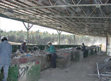
C&D recycling pick line
The Contractor may contract with a C&D recycling firm who accepts commingled debris. At the recycling site, concrete and masonry rubble are separated out of the debris for crushing into aggregate products. The remaining debris is typically crushed or shredded, then conveyed along a pick line for sorting and recycling. Recycling commingled debris and waste off-site requires virtually no adjustment in practice on the Contractor's part. C&D waste recyclers generally describe their fees as "competitive" with landfill disposal, which means a modest savings over prevailing landfill tipping fees. This method typically achieves a very high diversion rate. However, clean wood is frequently sold for boiler fuel, and some agencies do not allow incineration to be counted as diversion.
The Contractor may contract with individual recycling firms who deal in specific materials, in addition to a general waste hauler. This requires the Contractor, subcontractors and tradespersons to segregate waste, deposit it in the appropriate receptacles, and guard against contamination by other materials. The key to effective jobsite segregation is to place receptacles in the path of least resistance to the workforce, training the workforce to observe segregation practices, and policing the jobsite to prevent contamination. The construction process lends itself to on-site segregation. As trades enter and leave the jobsite, each generates a relatively homogeneous waste stream, given the specific tasks and the materials with which they work. As the recyclable materials are segregated, the recycling firms generally offer a higher price for the material (if the contractor hauls), or a lower hauling rate (if the recycler hauls). Alternatively, the Contractor can contract with a waste hauler who provides receptacles for recyclable materials and debris, and hauls all materials as a one-stop service. While some contend site separation increases the cost of construction, efficient materials movement and site layout should minimize any increased effort.

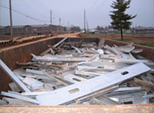
"Wood only" receptacle
"Metals only" receptacle with steel deck trimmings
- The waste diversion potential in a demolition scenario is considerable. The building's construction type and project schedule are the two primary factors in determining what and how salvage, reuse, and/or recycling can be accomplished. Consider the following:
- Develop the project schedule to accommodate salvage, reuse, or recycling. The quality and quantity of materials salvaged is a direct function to the time available for salvage.
- Prior to demolition, salvage as much useable material and components as the schedule will allow. Windows and doors, wood flooring, cabinetry, architectural millwork, electrical fixtures, plumbing fixtures, mechanical equipment anything that can be detached and removed can be usually be salvaged and reused. When developing the C&D Waste Management Plan, identify the most accessible and valuable materials, thereby optimizing the application of resources to this task.
- Concrete and masonry materials can be recycled to produce aggregate. This may be accomplished on-site with mobile equipment, or rubble can be hauled to a permanent recycling facility. Preferences vary among demolition contractors and recyclers about whether the building should be gutted prior to demolition, leaving only concrete and reinforcing to be crushed, or demolished intact, and the debris sorted as part of the concrete crushing process. Consider how the recycled concrete aggregate (RCA) will be used, what RCA products are most useable, and how the rubble should be processed to produce these products. If aggregate materials are required for the project, on-site recycling can provide these materials at a reduced net cost. The Construction Materials Recycling Association (CMRA) can provide information on methods and service providers.
- Landscape materials and wood that is not painted with lead-based paint, treated with an arsenic-based preservative, or otherwise contaminated with a hazardous or toxic material can be shredded into mulch, composted, or chipped for boiler fuel. This can be accomplished on-site or off-site. If mulch or compost is required for the project, shredding on-site can provide these materials at a reduced net cost.
- Structural steel and metals are almost universally recycled. This should be standard practice with any demolition contractor.
- Old growth timber is a valuable material and will usually justify the time required for a more delicate removal process. Timbers are generally sold through timber brokers to be cleaned and resold for timber framing, or as feedstock for high quality architectural millwork.
- Some species of dimensional lumber can also be quite valuable. Wood framed buildings can be partially or totally deconstructed. While this is often a more labor intensive approach, cost avoidance and the value of the materials can offset initial cost. The Building Materials Reuse Association (BMRA) can provide information on deconstruction contractors and used building materials retail businesses.
- If none of the alternative salvage, reuse, or recycling options are possible, mixed demolition debris can be hauled to a C&D debris recycling facility, as described above.


Segregated piles
Concrete recycling

Wood building deconstruction
Salvaged lumber at the jobsite
Application
Waste reduction practices are applicable to virtually any construction and demolition project scenario. The goal is to divert materials from landfill disposal to the greatest extent practical under the circumstances.
There are two opinions about whether this is a realistic expectation under real world project conditions. One is that waste reduction costs money, and the other is that waste reduction saves money. As with any construction project, planning and project management will ultimately dictate whether waste reduction is accomplished within the established cost, schedule, and quality parameters.
The greatest uncertainty is usually the availability of salvage and recycling services and outlets, and any costs associated with handling these materials. Resources are available to help Owners, A/E and CM professionals, and Contractors familiarize themselves with the salvage, reuse, and recycling industries and infrastructure. Examples are provided in Additional Resources, below.
The following sources provide case studies, or collections of case studies, on C&D waste diversion.
- Air Force Center for Engineering and the Environment, C&D Waste Management Guide (See Appendix D for 19 case studies)
- BuildingGreen, website features articles and case studies on C&D waste management
- California Department of Resources Recycling and Recovery (CalRecycle)—Case Studies Related to C&D Diversion Ordinances
- Powell Center for Center Construction and Environment, University of Florida
- Vermont Waste Management and Prevention Division
Emerging Issues
In an era of increasing energy prices, construction and demolition waste will be more widely recognized as a recoverable resource. Technology and attendant regulations may promote improvements in the diversion of wastes from the landfill and increasingly toward energy generation and recycling of materials.
Organic materials such as wood and plant wastes will increasingly be recognized as important components of biofuel feedstock in the generation of so-called green power.
Building product manufacturers will continue to look for and find opportunities to reclaim their used products, and to increase and promote their use of recycled materials into new and improved products.
Industrial recycling equipment manufacturers are investing in development of improved machinery which has potential to revolutionize the efficient sorting and diversion of waste. Industrial shredders reduce physical volume and produce particles of consistent dimension, allowing efficient mechanical separation. Industrial air separation technology allows efficient segregation of materials with differing mass characteristics, thus separating small pieces of wood and plastic from metal and aggregate.
International trade and shipping will continue to present opportunities and risks for the responsible diversion, recycling, and disposal of waste.
Public attention to issues of indiscriminate dumping of wastes will continue to pressure governments to ensure compliance with environmental regulations.
Solid waste landfills in the US sited in arid regions will continue to receive significant volumes of waste generated in urban areas. Landfills located in wet regions, near waterways, and in other environmentally sensitive areas will continue to trend toward closure. Post-closure expenses for management of landfills will continue to increase, with environmental monitoring and greenhouse gas management being significant priorities. Costs for disposal in many areas may continue to increase faster than the cost of energy, creating a de facto demand for increased diversion, recycling, and reuse.
Relevant Codes and Standards
- Executive Order 13693, "Planning for Federal Sustainability in the Next Decade"
- UFC 1-200-02 High Performance and Sustainable Building Requirements
Additional Resources
The following references are intended to provide further information about the C&D Waste Management subject. This list is only a sampling of available information.
WBDG
Design Objectives
Sustainable—Optimize Building Space and Material Use
Project Management
Project Planning, Delivery and Controls
Tools
Construction Waste Management Database, Building for Environmental and Economic Sustainability (BEES)
Federal Regulations
- Canadian Environmental Protection Act, 1999 (CEPA 1999), Environment and Climate Change Canada
Unified Facilities Guide Specifications (UFGS)
- UFGS 01 57 19 Temporary Environmental Controls
- UFGS 01 74 19 Construction Waste Management and Disposal
- UFGS 02 41 00 [Demolition] [and] [Deconstruction]
Army Corps of Engineers Engineering and Construction Bulletin (ECB)
Army Public Works Technical Bulletins (PWTB)
- PWTB 200-1-17 Recycling Interior Finish Materials - Carpet and Ceiling Tiles
- PWTB 200-1-23 Guidance for the Reduction of Demolition Waste Through Reuse and Recycling
- PWTB 200-1-24 Quantifying Waste Generated From Building Remodeling
- PWTB 200-1-26 Market Valuation of Demolition Salvage Materials
- PWTB 200-1-27 Reuse of Concrete Materials From Building Demolition
- PWTB 200-1-40 Characterizing Demolition Debris for Diversion Opportunities: WWII-Era and Korean War-Era Buildings
- PWTB 200-1-44 Recycling Exterior Building Finish Materials
- PWTB 200-1-45 Deconstruction of WWII-Era Wood Framed Buildings
- PWTB 200-1-48 Opportunities for Reducing Construction and Demolition Waste from Residential Communities Initiative (RCI) Programs
- PWTB 200-1-73 Reuse of Materials from Modular Relocatable Facilities
- PWTB 420-49-30 Alternatives to Demolition for Facility Reduction
Construction and Demolition Waste Management Information
- Characterization of Building-Related Construction and Demolition Debris in the United States, U.S. Environmental Protection Agency, Municipal and Industrial Solid Waste Division. Office of Solid Waste, Report No. EPA 530-R-98-010
- Construction and Demolition Recycling, King County Washington, Solid Waste Division
- Construction & Demolition Recycling Magazine
- Cradle to Cradle: Re-making the Way We Make Things by William McDonough & Michael Braungart. New York, NY: North Point Press, 2002.
- North Carolina Department of Environmental Quality
- "A Report on the Feasibility of Deconstruction: An Investigation of Deconstruction Activity in Four Cities" by U.S. Department of Housing and Urban Development
- Seattle Public Utilities: Construction and Demolition Waste Management
- Sustainable Managment of Construction and Demolition (C&D) Materials, U.S. EPA
- WasteCap—Construction & Demolition Waste Diversion
Environmental Life Cycle Information
- The American Institute of Architects The Environmental Resource Guide
- Impact Estimator for Buildings, Athena Sustainable Materials Institute
- International Council for Research and Innovation in Building and Construction
- Building for Environmental and Economic Sustainability (BEES), National Institute of Standards and Technology (NIST)
- Waste Reduction Model (WARM), U.S. EPA
Hazards
- U.S. EPA
Selected C&D Waste Management Guides
- C&D Guide Air Force Center for Engineering and the Environment
- CalRecycle Construction and Demolition Debris Recycling—Specifications
- A Guide to Deconstruction Deconstruction Institute
- 2007 King County/Seattle Contractors Guide King County, Washington
- King County Washington Design Specifications & Waste Management Plans
- Recycling Construction and Demolition Wastes: A Guide for Architects and Contractors, Massachusetts Department of Environmental Protection / Boston Society of Architects
- Minimizing Construction & Demolition Waste , State of Hawaii
- WasteSpec - Model Specifications for Construction Waste Reduction, Reuse, and Recycling , Triangle J Council of Governments, North Carolina
Building Materials Exchanges
- Build Reuse
- Directory of Wood Framed Building Deconstruction and Reused Building Materials Companies , U.S. Department of Agriculture, Forest Products Laboratory
- Georgia Industrial Materials Exchange
- North Carolina Recycling Markets Directory
- Recycler's World
- Southern Waste Exchange Information (SWIX) WasteXchange
Selected State, County, and Local Agencies
- California Department of Resources Recycling and Recovery (CalRecycle)
- City of New York Construction & Demolition Waste Manual
- Construction Industry Compliance Assistance Center—C&D Debris State Resources
- King County, Washington Construction & Demolition Recycling
- North Carolina Department of Natural Resources, Division of Pollution Prevention & Environmental Assistance
- StopWaste—Construction and Demolition Debris Alameda County, California
Recycling and Waste Management Councils
- Association of State and Territorial Solid Waste Management Officials See resource links to solid waste management websites for each of the 50 states and other federal resources
- Carpet America Recovery Effort
- Environmental Sustainability Resource Center
- National Recycling Coalition, Inc.
- Northeast Recycling Council
Associations
- American Industrial Hygiene Association
- ACGIH—American Council of Governmental Industrial Hygenists
- Build Reuse
- Construction & Demolition Recycling Association
- National Demolition Association
- Solid Waste Association of North America
Training and Certification Programs
- National Demolition Association Education & Events
- SWANA Certification: Managing Construction & Demolition Materials
Organizations
- Build Reuse
- Carpet America Recovery Effort
- Construction & Demolition Recycling Association
- Deconstruction & Reuse Network
- greenGoat
- Habitat for Humanity ReStore network
- The Loading Dock
- Reuse Development Organization
Tools
- WasteCap TRACE online C&D project documentation system, WasteCap Resource Solutions
Miscellaneous References
- Application of Updated Construction and Demolition Waste Reduction Policy to Army Projects , ERDC/CERL SR-15-1, December 2015.
- Concepts for Reuse and Recycling of Construction and Demolition Waste , ERDC/CERL TR-97/58, June 1999.
- Investigation of Mechanical Processes for Removing Lead Based Paint from Wood Siding , ERDC/CERL TR-06-30, September 2006.
- LBP Concerns in Producing Recycled Concrete Aggregate from Former Fort Ord Family Housing , ERDC/CERL TR-07-2, January 2007.
- On the Road to Reuse: Residential Demolition Bid Specification Development Tool, Report by EPA Region 5
- Regulatory and Policy Issues for Reuse and Remanufacture of Wood Materials Coated With Lead-Based Paint , Technical Report by USDA Forest Products Laboratory
- System Chemistry To Control Potential Environmental and Safety Hazards of Recycled Concrete Aggregate with Lead-Based Paint , ERDC/CERL TR-10-1, January 2010.
Construction-Operations Building Information Exchange (COBie)
Introduction
Within This Page
The handover of a new, or newly renovated, facility is celebrated by the project team, facility occupants, and owners. For those responsible to operate, maintain, and manage that facility, however, the work is just beginning. To start the facility manager begins by unpacking boxes of paper documents and retyping asset information and maintenance schedules into Computerized Maintenance Management Systems (CMMS). The pallets of boxes full of paper of operations and maintenance manuals and drawings shown in the figure below are typical of the requirements of contractors complying Unified Facility Guide Specifications 01 78 00 Closeout Submittals, and 01 78 23 Operations and Maintenance Data.
Facility managers have reported that this effort may require man-years of effort to create and review and transcribe hundreds of pages of documents, validate the transcriptions and manually enter data.
To transfer the cost of this manual data entry from the facility manager to the construction contractor, UFGS 01 78 24.00 20 Facility Data Workbook (FDW) requires the contractor to enter data directly into one specific CMMS.
Figure 1. Typical Delivery of Handover Documents
Even if a CMMS is used, mechanics need to search for information in these paper boxes to complete many of their jobs. Over time such documents are moved or lost which increases the cost to complete O&M activities and potentially increasing downtime of mission-critical facilities. A 2011 study predicted that 8% of the annual maintenance budget could be saved if open-standard electronic information were available to the technicians before starting complex work orders. Such savings could allow man-years of additional work towards backlogs or needed renovations. During the life of a project the owner collects and recollects information again and again, transcribing and then losing the same information over and over.
In 2007, the Construction-Operations Building information exchange (COBie) requirements analysis report proposed a new way for designers and contractors to directly provide electronic operations, maintenance, and asset management information as that information is created. Following an on-site study of COBie at Fort Lewis Washington, a proposed UFGS specification was developed for design-build and construction contracts. Further investigation of COBie compared the life-cycle costs of current and COBie-based processes and demonstrated that tens of thousands of man-hours or large projects are spent in performing redundant tasks trying to handle information locked-in documents.
Simply understanding, documenting, and proposing the information needs of operators, maintainers, and facility managers is insufficient to have COBie be used in practice. In parallel efforts the Engineer Research and Development Center, through the NIBS BIM Council (formerly buildingSMART alliance), worked to establish COBie as an internationally recognized open-standard implemented in over 30 Commercial Off-The-Shelf Software (COTS) systems.
Description
COBie is a performance-based specification for facility asset information delivery. Two types of assets are included in COBie: equipment and spaces. While manufacturer data for installed products and equipment may one day be directly available, COBie helps the project team organize electronic submittals approved during design and construction and deliver a consolidated electronic O&M manual with little or no additional effort. COBie data may then be imported directly into CMMS and asset management software, again at no cost. The PDF, drawing, and building information model files that accompany COBie are organized so that they can be easily accessed through the secure server directories already in place at the facility management office. The federal government's requirement for delivery of Real Property Inventory (RPI) information may be met by COBie.
While the technical details of COBie can appear complex. COBie files are not intended for end-users. COBie provides system-to-system exchange of the space and equipment information without user intervention. Consider COBie and similar "information exchange" projects to be a kind of "ASCII for buildings." Today, people don't need to know ASCII to use a web browser, email system, word processor, or other software; the words just come along because of ASCII. In the same way, once we have achieved COBie everywhere, only a very few programmers will need to give COBie a second thought.
To make COBie as useful as possible COBie data is available in several formats. Software system exchanges during the design process could use the STEP Physical File Format (ISO 10303 Part 21) files conforming to the Industry Foundation Class (ISO 16739) COBie Model View Definition. When people want to look at the COBie data directly, and they do not want to learn to read complex STEP file formats, they can use a translation of data into a spreadsheet. Examples of COBie files of different formats, and at various stages of design and construction, can be found on the Common BIM Files page. COBie spreadsheet templates may be found on links at the bottom of the COBie Means and Methods page.
Exchanges of small bits of COBie data about individual assets is another type of exchange supported by COBie. For example, an entire file need not be exchanged simply to update the installation date and serial number of a specific piece of equipment. These individual COBie transactions can be captured through National Information Exchange Model format called COBieLite.
Application
As in any other part of a design or construction contract, the quality of the product received depends on the ability of the designer or contractor to meet the specification. Before COBie, there was little need to clearly define the quality of the data provided since the volume of paper documents provided effectively prohibited more than a cursory review of the construction handover documents. Since COBie offers the possibility to automatically check the equality of electronic handover documents, the best owners will be sure they consider what to include in their COBie specification.
There are three sets of decisions owners can make to ensure that they get the information they need through COBie. The first is to specify the classifications they already use to organize existing CMMS data. If there is no CMMS data, COBie provides a default classification system, OmniClass, provided by the Construction Specifications Institute. The second set of decisions owners can make is to limit the set of scheduled information provided via COBie to only those assets that are actually managed or maintained. Finally, the owner can identify the specific properties to be mandated for each of these assets. Here again the default position is that COBie data simply reflect that data found on the drawing schedules. In most cases, such a level of detail will be well above the information currently captured. A brief video introduces COBie for owners.
From the designer's point of view, COBie data is simply the compiled set of all the schedules found on design drawings. Design software has been working hard since 2007 to ensure that they can export COBie data that matches their drawings. To ensure that design schedules can be properly exported to COBie designers should follow the instructions provided by their design software product. This brief video introduces the topic of COBie for designers.
From the contractor's point of view, COBie data is simply a way to produce construction submittals so information does not have be repeatedly copied and re-organized. Development of COBie data for the contractor should, if done correctly, also eliminate the need for equipment surveys. Properly compiled and organized COBie data also automatically produces O&M manuals. This brief video introduces the topic of COBie for contractors.
While facility managers will gain value from COBie on new facilities, they often express concern for about capturing COBie data collection on their existing building inventory. One 2009 study demonstrated that as-built COBie data surveys could be easily accomplished. Given management emphasis, the capture of COBie data for an entire campus may be accomplished in 12-14 months simply by modifying service and work orders forms.
Current Status
COBie began in late 2006 under the NIBS Facility Maintenance and Operations Committee. Small grants from NASA and the White House Office of Science and Technology Policy lead, within six months, to a initial specification that considered all available alternatives . As the NIBS Building Information Management (BIM) Council (formerly buildingSMART alliance) was formed, the first demonstration of software meeting the COBie requirements was held less than two years later at the National Academy of Sciences. Since March 2012 COBie has been part of the United States National Building Information Model Standard (NBIMS-US V2). An update to COBie to version 2.4 was balloted and approved in 2014 NBIMS-US V3.
Today COBie has been included in design and construction contracts in the United States, United Kingdom, and Singapore. There is no telling where it will turn up next since no one has to report their use of open standards! Given the typically slow pace of adoption of new technology in the construction industry, the progress of COBie has been nothing less than meteoric. This is not because COBie is perfect, or that COBie solves all problems related to BIM interoperability. This success is because COBie does one small job, and does it well. COBie delivers information about equipment and spaces at lower cost and higher quality than today's manual (or proprietary) methods.
COBie for Developers
If you are a software developer and want participate in the COBie project, there are several ways for you to engage. A COBie for construction committee was formed in January 2014 to assist those working in the construction and commissioning markets. For more information on the COBie for construction committee contact Mariangelica Carrasquillo-Mangual of the US Army Engineer Research and Development Center. Since only the leading handful of design software firms have implemented (or begun to implement) management of this group is accomplished directly by the COBie Project Committee.
While COBie began with a small Corps of Engineers project funded by NASA and the White House Office of Science and Technology Policy, COBie version 2.4 (included in NBIMS-US v3) is a national consensus effort. Efforts to make small improvements to COBie are always being discussed by members of the COBie Project Committee.
Relevant Codes and Standards
- COBie Practice Guide
- COBie 2.4 MVD (Technical Specification)
Templates and Additional Resources
COBIE FAQs
This page contains answers to frequently asked questions about the specifics of COBie. Click the A icon to view the answer to each question. If you have an additional question on COBie, submit through our comment form. Frequently encountered questions will be documented and added this list of FAQ's.
Operational Questions
Is COBie a building model? A
No, COBie is format for the publication of a subset of a building model. COBie's focus is on delivering building information not geometric modeling. COBie formatted building information is not an entire building model. COBie is a subset of a building model referred to as a "model view."
Do I have to fill out the whole COBie Spreadsheet? A
The amount of the COBie worksheets to fill in depends on the project stage. Project team members only enter the data for which they are responsible. Designers provide spaces and equipment locations. Builders provide manufacturer information and installed product data. Commissioning agents provide warranties, parts, maintenance information. For more details please see the COBie Means and Methods page.
When do I deliver COBie data? A
COBie data is delivered along with, or in lieu of, existing contract deliverables depending on your specific contract. COBie does not change the content of existing contract deliverables. COBie does, however, change the format of the information that is delivered. An example specification for the delivery of COBie files may be found here. Delivery of COBie is an information publication activity. The delivery of a COBie data set is not an invitation to share a building model since COBie is simply a set of published building information.
Why is COBie a spreadsheet? A
Given a large project and progressive owner, there will be sufficient overheads needed to provide a wide range of value-added services that may include the proprietary development of Facility Handover data sets. Most public projects are, however, relative simple, square buildings, completed on a shoestring budget with taxpayer funds. An open exchange format for facility handover data must, therefore, accommodate both the large custom buildings and small public buildings with the least common denominator of technology allowing the widest possible set of project stakeholders. COBie for large projects uses IFC-standard STEP and ifcXML formatted files. Small projects may exchange COBie data, displayed as spreadsheets, and directly update COBie data using these common spreadsheet programs.
How is COBie updated for specific clients? A
COBie is a standardized format but it's contents are configurable for regional and project practice. The only changes needed are values for columns in the PickList Worksheet. The green columns are client, national, or regional classifications and can be updated. The green coded COBie values are provided as default settings only. PickList Worksheet columns in non-green colors should NOT be changed because they will result in inconsistent use of COBie data by software vendors. For example, the values for 'FloorType' is always one of the three values 'Site', 'Floor', or 'Roof' and coordinates are taken from the 5 values that describe a point, line, or box.
What products and equipment do I include in COBie? A
All products and equipment listed in design schedules, should be found in the COBie file under the Type and Component Worksheets. Type worksheets identify the category of product. Components are specific instances of each of the Types, typically found in one room. Components must be listed by room. Components that link or span rooms must be listed in each applicable room. Interior doors, for example, should be listed in both spaces that the doors connect.
What software is required to create COBie? A
The COBie Specification is a performance specification. This means that it doesn't matter what software is used to create COBie information, as long as the format of the information meets the COBie specification and the content of the COBie file reflects your specific project. Software vendors have begun to directly export to COBie, however, on small projects COBie may also be created or updated by hand directly in the spreadsheet version of the COBie data.
What if my software doesn't support COBie today? A
Often software that doesn't directly export COBie today will export spreadsheet formatted information in a different order than that provided by COBie. Such information may cut and paste into COBie creating the start of the COBie file without rekeying room and equipment schedules.
Where is the COBie submittal register? A
The submittal register is held within the Document Worksheet. The set of all documents identified in the designer COBie file as 'Required' can be used to create a submittal register. Use of a web-based submittal register to automatically linked manufacturer documents to building information (models) is essential to the cost-effective implementation of COBie. One web-based submittal register that may be used is the eSubmittal module of ProjNetSM.
How to I check a COBie file? A
A free program has been created to allow you to directly check a COBie file. This command line program is provided without technical support.
Technical Questions
How many buildings can be exchanged using COBie? A
Each COBie file should contain a single building. If there are multiple buildings in a given project, each of these buildings should be held it their own COBie worksheet.
Can COBie Spaces contain other Spaces? A
No. Spaces cannot contain other spaces. Zones should be used instead as super elements that may contain multiple spaces.
What is are COBie Zones? A
A Zone is a group of spaces that together provide a specific function. A common example of a zone is a group of spaces that the public are allowed to access, and a group of spaces that may only be accessed by employees.
What are COBie Systems? A
A System is a group of components that work together to provide a specific building service such as ventilation or fire protection. In COBie systems are described by their lowest level. In a two story building, for example, one may describe the HVAC system as two separate systems, '1st Floor HVAC,' and '2nd Floor HVAC.'
What fields are required to be unique within COBie? A
The first column of each worksheet, called 'Name,' is the unique name for all the rows in that worksheet. Names must avoid unusual punctuation. Using Names, as opposed to row numbers, ensures users' cut-and-pastes across worksheets provide consistent information. For example each worksheet can be prepared from reports produced by disparate applications and then merged into the COBie worksheet. Also character names have been preferred as a miss-typed character is more likely to make a key invalid, whereas a mistyped number is more likely to be a valid but wrong key.
What columns are required in COBie? A
COBie is color coded. Yellow coded columns are mandatory. These columns must contain a value. If you do not have, or know the value, enter 'n/a' standing for not applicable or not available.
Where can I add properties to COBie? A
The Attribute worksheet is used to record the attributes of the Components, Types, Systems, Zones and Spaces. One attribute Value record is recorded for a given Attribute Name, SheetName and RowName. Values held for a Type and System can be expected to be overridden by values held against an individual Component. Values held for a Zone can be expected to be overridden by values held against an individual Space.
Consultants and Studies: Project Fire Protection Engineer - Qualifications and Scope of Services
Consultants and Studies: Site, Topographic, Utility, Landscape and Soil Survey - Scope of Services
Consultants and Studies: Subsurface Investigation Study
Continuous Child Care Facilities
Overview
Within This Page
The Continuous Child Care Facility (CCCF) provides around-the-clock child care to support families for whom the typical Child Development Center's (CDC) operating hours are not adequate. The need for around-the-clock care is driven by the requirements of parents with atypical schedules, emergencies, or other unplanned absences. These might include night-time shift work or unforeseen in-patient medical care.
In general, CCCFs seek to combine the strengths of in-home-style care with those of center-based care. However, just like a CDC, the CCCF must be designed to provide safe, nurturing, and stimulating environments essential for healthy child development. The CCCF will provide this environment on a smaller scale and in a facility designed to replicate a home. For example, a CCCF includes a living room, play room, dinning room, and bedrooms to accommodate the different functions and activities that the CDC accommodates in classrooms/child activity rooms. The CCCF design may vary based on facility mission, including the age of the children accepted and the length of stay allowed.
As with a CDC, there are nationally recognized accreditation agencies, such as the National Association for the Education of Young Children (NAEYC), that identify requirements for quality child development programs.
Building Attributes
A. Space Types and Building Organization
CCCF facility spaces are intended to emulate typical residential spaces. Administrative space is minimal.
- Foyer. Primary facility entry and check-in, should allow entering children to view other children in living and play rooms.
- Living room. Gathering and quiet social activity area
- Play room. Gathering and play area with a variety of structured activity subareas
- Dining room. Family-style dining area for all children, also accommodating table-based activities such as crafts and homework
- Kitchen. Full-service, residential-style kitchen
- Crib/infant room. Sleeping space and infant activity area, including diaper changing facilities
- Bedrooms. Separate rooms for boys and girls
- Child toilets. These may be unisex facilities and/or gender-specific facilities and include child-sized fixtures and a bath/shower.
- Staff den / office
- Staff toilet
- Laundry
- Storage
- Outdoor activity area. Fenced activity area for children
Spaces are organized to achieve the key goals of supervising the children, maintaining a home-like setting, and providing ample space for active play. Explore opportunities to dual-use circulation space as additional activity area for children: To the degree possible, open areas should easily flow from one to the other in order to maximize gross motor activity areas for children.
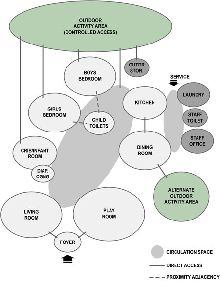
Sample bubble diagram for a continuous child care facility. Developed by EwingCole and U.S. Cost, Inc.
B. Design Considerations
Key design goals and considerations for CCCF are very similar to those for CDCs, with special emphasis on the following:
Be Homelike
Even more than in a CDC, a CCCF is designed to emulate a single-family residential environment. (However, as these are commercial facilities, the applicable facility classification and building codes may be more stringent than residential codes.) Pay particular attention to the following:
- Provide a sense of arrival and welcome upon entering the facility for both children and parents
- Allow children to independently address bodily needs such as hunger, thirst, using the toilet, and sleep
- Avoid institutional, unnatural finishes and textures. Use natural finishes to the extent possible or a natural appearance when not possible. For example, resilient sheet flooring should have a simulated stone or wood-grain pattern.
Maintain a Safe and Healthy Environment
Safety is a critical element of CCCF design and includes both child-abuse prevention as well as injury prevention:
- Provide vision panels in all interior doors
- Ensure controlled access to the facility, including outdoor spaces
- Provide window treatments that are either cordless, have cords that are out of reach of children, or have continuous-loop cords that are permanently anchored to the wall
- Specify easily cleaned finishes
- Provide good indoor air quality as well as to the use of daylighting, non-toxic building materials and improved maintenance practices
- Use rounded corners (½" bull-nose) on all counters, casework, and furnishings
Provide a Durable and Maintainable Facility
The continuous use (24 hours per day, 7 days per week) and gross motor activities will impact the facility interior:
- Provide durable interior finishes and furnishings while maintaining a residential-style appearance
- Use solid surface/solid composite counters
- Provide heavy-duty, "professional" grade, residential appliances for the kitchen and laundry
Emerging Issues
The very need for the CCCF is an emerging issue as the modern family has increasingly complex time demands, requiring flexible child care. This is particularly true for military families that may include deployed or wounded parent(s). The CCCF provides an alternative to in-home care services for parents that also want the added safety and security of center-based care facilities.
Relevant Codes and Standards
Standard federal and state building codes apply, as appropriate.
Department of Defense
- FC 4-740-14N Navy and Marine Corps Child Development Centers
- UFC 4-740-14 Design: Child Development Centers (USACE and Air Force Only)
- UFC 4-740-15 Continuous Child Care Facilities
Additional Resources
Publications
- Caring for Our Children, National Health and Safety Performance Standards: Guidelines for Out-of-Home Child Care Programs, American Academy of Pediatrics, American Public Health Association, National Resource Center for Health and Safety in Child Care and Early Education.
- The Safe Nursery, Consumer Product Safety Commission
- Public Playground Safety Handbook, CPSC Publication #325 , Consumer Product Safety Commission
CONUS - Altus AFB IFS
This Installation Facilities Standards (IFS) document is part of the Air Force Corporate Facilities Standards (AFCFS) program and provides facility design standards for Altus Air Force Base. IFS replaces the Architectural Compatibility Guide (and similar legacy documents), as a component plan of the Installation Development Plan (IDP). For more information contact the Base Civil Engineer.
CONUS - Arnold AFB IFS
This Installation Facilities Standards (IFS) document is part of the Air Force Corporate Facilities Standards (AFCFS) program and provides facility design standards for Arnold Air Force Base. IFS replaces the Architectural Compatibility Standards (and similar legacy documents), as a component plan of the Installation Development Plan (IDP). For more information contact the Base Civil Engineer.
CONUS - Barksdale AFB IFS
This Installation Facilities Standards (IFS) document is part of the Air Force Corporate Facilities Standards (AFCFS) program and provides facility design standards for Barksdale Air Force Base. IFS replaces the Design Standards document (and similar legacy documents), as a component plan of the Installation Development Plan (IDP). For more information contact the Base Civil Engineer.
CONUS - Beale AFB IFS
This Installation Facilities Standards (IFS) document is part of the Air Force Corporate Facilities Standards (AFCFS) program and provides facility design standards for Beale Air Force Base. IFS replaces the Design Compatibility Guide (and similar legacy documents), as a component plan of the Installation Development Plan (IDP). For more information contact the Base Civil Engineer.
CONUS - Buckley AFB IFS
This Installation Facilities Standards (IFS) document is part of the Air Force Corporate Facilities Standards (AFCFS) program and provides facility design standards for Buckley Air Force Base. IFS replaces the Facilities Excellence Plan (and similar legacy documents), as a component plan of the Installation Development Plan (IDP). For more information contact the Base Civil Engineer.
CONUS - Cheyenne Mountain AFS IFS
This Installation Facilities Standards (IFS) document is part of the Air Force Corporate Facilities Standards (AFCFS) program and provides facility design standards for Cheyenne Mountain Air Force Station. IFS replaces the Facilities Excellence Standards (and similar legacy documents), as a component plan of the Installation Development Plan (IDP). For more information contact the Base Civil Engineer.
CONUS - Columbus AFB IFS
This Installation Facilities Standards (IFS) document is part of the Air Force Corporate Facilities Standards (AFCFS) program and provides facility design standards for Columbus Air Force Base. IFS replaces the Architectural Compatibility Plan (and similar legacy documents), as a component plan of the Installation Development Plan (IDP). For more information contact the Base Civil Engineer.
CONUS - Davis-Monthan AFB IFS
This Installation Facilities Standards (IFS) document is part of the Air Force Corporate Facilities Standards (AFCFS) program and provides facility design standards for Davis-Monthan Air Force Base. IFS replaces the Design Compatibility Guidelines document (and similar legacy documents), as a component plan of the Installation Development Plan (IDP). For more information contact the Base Civil Engineer.
CONUS - Dover AFB IFS

This Installation Facilities Standards (IFS) document is part of the Air Force Corporate Facilities Standards (AFCFS) program and provides facility design standards for Dover Air Force Base. IFS replaces the Architectural Compatibility Plan (and similar legacy documents), as a component plan of the Installation Development Plan (IDP). For more information contact the Base Civil Engineer.
CONUS - Dyess AFB IFS
This Installation Facilities Standards (IFS) document is part of the Air Force Corporate Facilities Standards (AFCFS) program and provides facility design standards for Goodfellow Air Force Base. IFS replaces the Installation Development and Design documents (and similar legacy documents), as a component plan of the Installation Development Plan (IDP). For more information contact the Base Civil Engineer.
CONUS - Edwards AFB IFS
This Installation Facilities Standards (IFS) document is part of the Air Force Corporate Facilities Standards (AFCFS) program and provides facility design standards for Edwards Air Force Base. IFS replaces the Design Standards document (and similar legacy documents), as a component plan of the Installation Development Plan (IDP). For more information contact the Base Civil Engineer.
CONUS - Eglin AFB IFS
This Installation Facilities Standards (IFS) document is part of the Air Force Corporate Facilities Standards (AFCFS) program and provides facility design standards for Eglin Air Force Base. IFS replaces the Architectural Compatibility Plan (and similar legacy documents), as a component plan of the Installation Development Plan (IDP). For more information contact the Base Civil Engineer.
CONUS - Ellsworth AFB IFS

This Installation Facilities Standards (IFS) document is part of the Air Force Corporate Facilities Standards (AFCFS) program and provides facility design standards for Ellsworth Air Force Base. IFS is a component plan of the Installation Development Plan (IDP) and supersedes previous design standards documents. For more information contact the Base Civil Engineer.
CONUS - Fairchild AFB IFS
This Installation Facilities Standards (IFS) document is part of the Air Force Corporate Facilities Standards (AFCFS) program and provides facility design standards for Fairchild Air Force Base. IFS replaces the Architectural Compatibility Plan (and similar legacy documents), as a component plan of the Installation Development Plan (IDP). For more information contact the Base Civil Engineer.
CONUS - FE Warren AFB IFS
This Installation Facilities Standards (IFS) document is part of the Air Force Corporate Facilities Standards (AFCFS) program and provides facility design standards for FE Warren Air Force Base. IFS replaces the Facilities Excellence Plan (and similar legacy documents), as a component plan of the Installation Development Plan (IDP). For more information contact the Base Civil Engineer.
CONUS - Goodfellow AFB IFS
This Installation Facilities Standards (IFS) document is part of the Air Force Corporate Facilities Standards (AFCFS) program and provides facility design standards for Goodfellow Air Force Base. IFS replaces the Architectural Compatibility Guide (and similar legacy documents), as a component plan of the Installation Development Plan (IDP). For more information contact the Base Civil Engineer.
CONUS - Grand Forks AFB IFS
This Installation Facilities Standards (IFS) document is part of the Air Force Corporate Facilities Standards (AFCFS) program and provides facility design standards for Grand Forks Air Force Base. IFS replaces the Architectural Compatibility Plan (and similar legacy documents) and is required by Air Force Instruction (AFI) 32-1023. For more information contact the Base Civil Engineer.
CONUS - Hill AFB IFS
This Installation Facilities Standards (IFS) document is part of the Air Force Corporate Facilities Standards (AFCFS) program and provides facility design standards for Hill Air Force Base. IFS replaces the Architectural Compatibility Plan (and similar legacy documents) and is required by Air Force Instruction (AFI) 32-1023. For more information contact the Base Civil Engineer.