Air Support Operations Squadron (ASOS)
Status
Active
Publish Date
FFC Agency & Library
<p>Replaced by: <a href="/dod/ufc/ufc-4-133-01" target="_blank">UFC 4-133-01</a></p>
This Design Guide provides basic guidance and criteria to programmers, planners, architects, engineers, design and construction agents, commanders, and construction contractors for the programming, design, and construction or renovation of Air Traffic Control Towers (ATCT). Specific items herein are minimum standards, and may be modified by particular requirements of the base or other special design parameters. For latest information and drawings, plans, utility, siting and electronic requirements, consult the Air Force Flight Standards Agency (AFFSA).
This design guide provides the basic criteria to organize, evaluate, plan, program, and design Air Mobility Command (AMC) Aircraft Industrial Support Facilities (AISF). It applies to the design of all new construction and renovation projects. The information presented is intended to make commanders and their staff aware of important design considerations and to aid them in project development. Quality facilities will improve the maintenance specialists efficiency and ability to service and repair equipment and encourage pride of ownership in their work space.
This guide provides the basic criteria to evaluate, plan, program, and design maintenance training facilities to house all AMC maintenance training functions, including AETC resources. It is intended to ensure personnel are aware of important design considerations and to aid in project development.
This design guide provides the basic criteria to organize, evaluate, plan, program, and design Air Mobility Command (AMC) Airman Leadership School (ALS) facilities.
While the large majority of energy used in the United States still comes from fossil fuels (see EIA for example), there is also tremendous growth in alternative and renewable energy technologies. In this context, alternative energy refers to energy not derived from traditional fossil fuel sources (coal, natural gas, petroleum) through conventional processes. Renewable energy is a subset of alternative energy; according to the National Renewable Energy Laboratory (NREL), "Renewable energy resources—such as wind and solar energy-are constantly replenished and will never run out."
Both market and regulatory forces are driving increased adoption of renewable energy. The Energy Policy Act of 2005 (EPACT), for example, calls for federal agencies to obtain at least 7.5% of their electricity from renewable sources. To stimulate development of new renewable energy projects, Executive Order 13693 requires federal agencies to explore on-site renewable energy generation at their facilities. Many states around the nation have implemented renewable portfolio standards (RPS) mandating a minimum fraction of renewably generated energy in all electricity sold. The Database of State Incentives for Renewables and Efficiency (DSIRE) has information on some of these RPS's.
In conjunction with regulatory requirements for renewable energy, costs of fossil fuels remain rather high and costs of some renewable and alternative energy technologies are coming down. This article focuses on several such energy sources, with a primary focus on electricity generation. The practical use of these systems varies with the specific technology, application, location, cost of energy, and other factors. While many of the technologies are becoming more cost-effective, alternative energy generation is not a substitute for reliable energy efficiency strategies. Implementing efficiency strategies first is still the best approach to meet most energy goals.
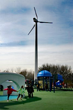
For centuries, people have harnessed energy in the wind—historically this has been used as mechanical energy for milling or water pumping. Wind-powered water pumps are still used in remote areas of the U.S., but harnessing the wind to generate electric energy has become much more common. In modern wind turbines, kinetic energy in the wind is converted to rotational energy and then to electrical energy. This electricity is then conditioned and—in most cases—sent into the utility grid.
In some parts of the country, wind energy has become cost-competitive with conventional sources of electricity generation. There are a growing number of wind generators available with capacities ranging from a few hundred watts (powering small off-grid homes, sailboats, etc.) to several megawatts (for utility-scale generation). The physical size of these generators has a similar range&mdsh;diameters from 3–4 feet to 300–400 feet.
Wind generators are certainly most effective in areas with consistent, high-speed winds. Trees, buildings, and topography can slow winds down tremendously. In the United States, the best wind resources are generally near the coasts (off-shore) or on the Plains. DOE, NREL, and others have developed wind resource maps for the country and some states have developed more detailed maps.
Proper location of wind turbines is critical. Because there can be wide variations in wind speed over small distances, best practices often call for monitoring wind resources at a site (or several potential sites) for a year or more. With smaller generators (several kilowatts), turbines should typically be mounted 30–50 feet above the next highest object in a 500-foot radius (trees, buildings, etc). Larger generators are centered 100 feet or more off the ground where wind speeds are higher and less turbulent.
Because most electric energy is used in buildings, many people have explored mounting wind turbines on top of buildings. This is often not a viable strategy because of the weight, vibrations, torque, and noise of the generators. To get access to higher wind speeds, generators should be positioned well above nearby buildings. There are some wind generator products, however, specifically designed for mounting on buildings. They are usually small (typically 2000 Watts or less) and are still subject to wind speed and turbulence limitations.

Wind turbines mounted on an apartment building in the Bronx, New York Photo credit: Steven Winter Associates, Inc.
A wind turbine at a Massachusetts school Photo Credit: Northern Power Systems
While small, building-mounted turbines can be appealing to designers, larger turbines (located far above buildings and other obstructions) are much more effective with respect to electricity generation.
Biomass power generation typically refers to the combustion of plant material to power turbines which—in turn—generate electricity. The term biofuel generally refers to a fuel derived from plant material (biomass) that can be used in lieu of conventional fossil fuels.

An efficient wood stove in a new home Photo Credit: Steven Winter Associates, Inc.
The oldest use of biomass energy is burning wood to keep warm. This is still quite common in homes today, and there are also more advanced boiler systems that burn wood to heat water for use in homes or larger buildings. Some of these devices are designed to burn wood pellets rather than larger pieces of wood. Wood pellets are small (less than one inch) pieces of processed biomass from a variety of sources (wood chips, sawdust, waste from wood processing, etc.) Pellet-burning appliances typically have hoppers that feed the fuel to the firebox at a controlled rate—making pellet burning easier to control than some other types of biomass appliances. More information on this and other wood burning technologies for buildings is available through ENERGY.GOV Energy Saver pages.
On larger scales, many timber and agricultural industries burn wood and agricultural waste to obtain useful heat—the heat can be used directly or used to power turbines to generate electricity. When the biomass fuel is inexpensive—especially when it is a waste product—such power generation can be very cost-effective.
As with burning of fossil fuels, burning biomass releases carbon dioxide and other pollutants. Because the carbon in biomass has quite recently been absorbed from the atmosphere, if the biomass resource is managed sustainably there may be little net-emissions of carbon dioxide. This closed carbon cycle, however, does not necessarily include any energy needed to cultivate, harvest, and process the biomass. In addition to pollutants, opponents of biomass generation cite potential effects on regional agriculture or forestry. With growing demand for biomass, there may be pressure to harvest resources in less sustainable ways.

Fuel pump with 20% biodiesel (B20), 85% ethanol, and standard unleaded fuel with 10% ethanol. Photo Credit: Charles Bensinger and Renewable Energy Partners of New Mexico
As described above, biofuels are fuels derived from biomass that can be used in place of conventional fossil fuels. The two most common biofuels are ethanol and biodiesel. Ethanol is currently used in gasoline mixtures to power many automobiles. Most of this ethanol comes from the fermentation of sugars found in food crops, primarily corn. Federal incentives make this cost-effective, but there is growing concern that using ethanol derived from fermentation of corn sugars is not sustainable; there may be more energy needed to cultivate, harvest, and process the material than is contained in the final fuel produced. Other ethanol production strategies—using cellulosic material rather than sugars—can derive ethanol from wood chips, leaves, agricultural waste, and similar material. These show promise with respect to sustainability, but they currently have substantially higher costs (see EERE Newsletter for more information).
Biodiesel is made by converting natural oils—usually vegetable oils—into usable fuels. The fuel can be used in many engines or combustion appliances designed for diesel or no. 2 fuel oil. The appliances typically need no or minor adjustments, though sometimes a blend of biodiesel and petroleum results in best operation. The manufacturing process is well understood and quite environmentally benign. The chief limitation of biodiesel manufacture is a cost-effective, sustainable source of vegetable oils.
Waste oils were one of the first targets for biodiesel manufacturers. In some areas, restaurant managers—who used to pay substantial fees to dispose of waste cooking oils—found new consumers who were willing to take waste oil at no charge, or even to pay for the used oil. While truly sustainable, such waste oil results in a very small volume of biodiesel. Most fuel is generated from virgin vegetable oils, especially oils from soy or rapeseed. Most experts agree that biodiesel manufacture is much less energy-intensive than conventional ethanol production—i.e. much less energy is used to create the fuel than is contained in the final fuel product.
Solar energy systems in buildings include systems that capture heat (such as solar water heating systems and passive heating), and systems that convert solar energy into electricity. The latter is done primarily through photovoltaic (PV) systems. PV technology has seen dramatic improvements—and cost reductions—since its first applications in the space program in the 1960's. While the technology is still not inexpensive, from 2006 to 2010, installed costs of PV systems have dropped 30–40%. This drop—combined with higher energy costs, government and/or utility incentives, and time-of-use electric rates—have made PV cost-effective in a growing number of applications.
The heart of PV technology is in the semi-conductors (mostly silicon-based) used in the PV modules themselves. The modules convert sunlight to direct current (DC) energy; the DC energy is typically then converted to alternating current (AC) energy via inverters. From the inverters, energy is typically fed into a building's electric system or exported to the utility grid.
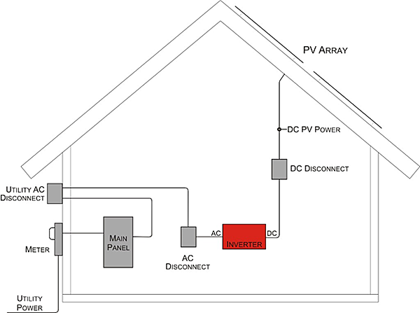
Simple schematic showing the main components of a PV system and how it is typically incorporated into a building—in this case a home.
The amount of electricity that a PV system generates depends upon the amount of sun received and many other installation parameters (tilt, orientation, shading, etc.). A simple and accurate tool for predicting generation is PVWatts, developed by NREL.
As PV collectors need direct sun, they are often mounted on roofs. While not extremely heavy, structural factors must be taken into account in planning a roof-top installation. Designers need to be aware of mounting requirements, ballast, and wind loads. Any roof penetrations (for mounting or electrical) need to be planned for and detailed properly. Panels should face south (in the northern hemisphere) and shade (from trees, other buildings, roof-top equipment, etc.) should be minimized. In some cases, PV collectors can be incorporated as part of the roof or building envelope; see the Building-Integrated Photovoltaics page for more information.
While most PV collectors are mounted in stationary positions, some free-standing arrays use devices to track the path of the sun across the sky. This can increase electricity generation substantially (20% or more), but it also adds cost and complexity to the system. PV modules themselves are very durable and have no moving parts; most warrantees are 20–30 years. Inverters are usually shorter-lived; these warrantees are typically 5–10 years.

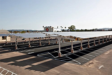
PV system on a mail processing center in Los Angeles. PVs are one of the most reliable renewable energy technologies, and building integration can be straightforward. Photo Credit: Bill Golove
PVs can also be mounted on the ground or auxiliary structures. These collectors provide shade for parked cars at MCAS Miramar. Photo Credit: MCAS Miramar
Temperatures at the bottom of the Earth's crust—some 5–40 miles below the surface—are typically over 1000°F. In a few locations, these high temperatures reach closer to the surface resulting in volcanic activity, hot springs, geysers, and the opportunity for geothermal electricity generation. Geothermal plants tap relatively shallow pockets of steam; the steam is used to operate turbines that generate electricity.
Clearly, geothermal generation is very location dependent. According to Department of Energy sources, there is approximately 3,000 MW of geothermal electricity generation capacity in the United States. Researchers say, however, that there is potential for 100,000 MW of generation using the latest technologies. At some locations where the accessible geothermal resources are not at sufficient temperature to generate electricity cost-effectively, the heat can be used directly (for industrial processes, space heating, etc.) In the United States, nearly all generators—and most potential sites—are located in the western part of the country (see map).
The term "geothermal" is also sometimes used to refer to ground source heat pumps (GSHPs). While not a means of generating renewable energy, GSHPs can be part of an efficient HVAC system.
When a fuel—fossil-based or otherwise—is converted to electricity, there is also a substantial amount of heat generated. Usually the quantity of heat generated is far greater than the quantity of useful electricity; typically 30–40% of energy in a fossil fuel is converted to electricity using conventional technologies. Cogeneration or combined heat and power (CHP) is a strategy whereby both useful heat and electricity are obtained from processing a fuel.
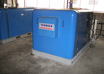
These cogeneration units provide electricity to meet some of the base load in a New York City apartment building. While the up-front and maintenance costs are significant, the cost of the natural gas used to generate electricity is less than the cost of electricity purchased from the utility. The thermal energy the engines provide—used for water heating—results in additional natural gas savings of over $10,000 per year. Photo Credit: Steven Winter Associates, Inc.
The concept itself is not new. For nearly as long as people have been burning fuel to generate electricity, people have been looking for ways to utilize the excess heat generated. Newer technologies, combined with higher energy rates, allow smaller-scale, distributed cogeneration to be more cost effective in some buildings or campuses.
Cogeneration is a strategy that includes many types of distributed generation technologies such as turbines, micro-turbines, reciprocating engines, and fuel cells. The most common fuel for these cogeneration technologies is natural gas. A great deal of ongoing research and development focuses on hydrogen fuel cells, but most hydrogen is also currently derived from natural gas. While cogeneration can be considered an alternative energy technology, it is not renewable when it relies on fossil fuels.
Cogeneration is most effective where both electrical and thermal loads are predictable, steady, and coincident. For example, thermal demands for space heating in the winter and electrical demands for space cooling in the summer are not a good match for cogeneration. At the same site, however, there may be steady, year-round thermal loads (e.g. service water) and baseline electrical loads (lighting, equipment, HVAC base loads, etc.). It is possible that a properly sized cogeneration system could cost-effectively meet the base loads while additional heat and electricity would be obtained at lower cost from conventional sources. An accurate knowledge of load patterns—both thermal and electric—is key in designing a good cogeneration system.
Hydropower is one of the oldest and most prevalent renewable energy technologies, accounting for over 10% of all U.S. electricity in 1996 (EIA). By 2009, however, this fraction dropped to below 7%. Hydropower generation itself dropped 22% over this period. While certainly renewable, conventional hydropower is often not sustainable. The effects of dams on river ecologies are frequently dramatic, and working dams have been removed in an attempt to restore riparian ecosystems.
A beta hydrokinetic generator to be installed near Eastport, ME—location of some of the largest tides in the U.S. Photo Credit: Ocean Renewable Power Company
While it is possible to create sustainable hydropower systems in rivers, these systems tend to be smaller (see EERE resources for more information). Hydropower generation is also moving away from dams towards hydrokinetic systems—systems that use the natural flow of water rather than damming or diverting flow through conventional turbines. There are many types of emerging hydrokinetic technologies; some are designed for rivers, some for ocean areas with strong tidal flows, and some designed to harness energy in ocean waves.
While many alternative energy technologies are becoming more viable and affordable, renewable energy is still often much more expensive than energy efficiency; it is usually much less expensive to save energy than to generate renewable energy. The most cost-effective route to meet the EPAct (or other) renewable energy goals will likely include both increasing the numerator (renewable energy) as well as decreasing the denominator (total energy) in the renewable energy fraction equation:

Understanding total energy use at a facility is also important when exploring appropriate alternative energy systems. Cogeneration systems, for example, should be sized to meet consistent electrical and thermal loads in order to be practical and cost-effective. If power used for space cooling represents a large expense, a PV system sized to reduce this peak can translate into more significant cost savings.
During planning of alternative generation systems, it is critical to consider integration into existing electrical systems and/or the utility grid. Requirements for utility interconnection vary state-by-state and often utility-by-utility. Links to several state regulations can be found at DSIRE; check with local utilities and/or regional authorities for specific permitting and interconnection requirements.
Site considerations are also important during planning. In addition to the obvious (e.g. PV systems should not be shaded, wind turbines should have access to consistent winds), designers should consider aesthetic and noise impacts of the technologies.
Finally, in planning for alternative energy systems, consider ongoing operation and maintenance requirements. O&M requirements for these technologies vary widely. In addition to the costs, make sure the facility or staff has the resources needed to keep the systems operating at peak performance.
This document contains scoping and technical requirements for accessibility to sites, facilities, buildings, and elements by individuals with disabilities. The requirements are to be applied during the design, construction, additions to, and alteration of sites, facilities, buildings, and elements to the extent required by regulations issued by Federal agencies under the Americans with Disabilities Act of 1990 (ADA).
The Department of Justice (DOJ) updated its ADA Standards in 2010, which are referred to as the 2010 ADA Standards for Accessible Design. These standards, which replace the original ADA Standards DOJ issued in 1991, became mandatory for newly constructed and altered facilities as of March 15, 2012. DOJ’s ADA Standards apply to all facilities covered by the ADA except public transit facilities.
The Department of Transportation (DOT) issued its current edition of the ADA Standards in 2006. These standards apply to facilities used by state and local governments to provide public transportation. They became effective on November 29, 2006 and replace earlier standards issued by DOT in 1991.
This document contains scoping and technical requirements for accessibility to sites, facilities, buildings, and elements by individuals with disabilities. The requirements are to be applied during the design, construction, additions to, and alteration of sites, facilities, buildings, and elements to the extent required by regulations issued by Federal agencies under the Americans with Disabilities Act of 1990 (ADA).
This new design document is the culmination of a comprehensive, decade-long review and update of the Board’s ADA Accessibility Guidelines, which were first published in 1991. Revisions have been made so that the guidelines continue to meet the needs opeople with disabilities and keep pace with technological innovations. For example, new provisions for ATMs specify audible output so that people with vision impairmentare provided equal access, and reach ranges have been lowered to better serve peoplewho use wheelchairs and persons of short stature. The guidelines also feature a new format and organization and have been extensively edited for greater clarity.
As part of this update, the Board has made its guidelines more consistent with model building codes, such as the International Building Code (IBC), and industry standards.It coordinated extensively with model code groups and standard-setting bodies throughout the process so that differences could be reconciled. As a result, a hilevel of harmonization has been achieved which has brought about improvements to thguidelines as well as to counterpart provisions in the IBC and key industry standards, including those for accessible facilities issued through the American National StandardInstitute (ANSI). The Board believes that this achievement will greatly facilitate compliance.
The purpose of this Building Type page is to assist in the planning and/or design of new Ammunition and Explosive (AE) storage magazines for the Department of Defense (DoD) by providing definitions, descriptions, requirements, and standards of drawings and specifications as available. The information is intended to offer a general introduction into the design and approval of AE storage magazines. For additional information refer to the DoD Component-specific explosives safety documents and the DoD explosives safety manual referenced below.
The Department of Defense Explosives Safety Board (DDESB) has established uniform minimum AE safety standards for personnel and property that have the potential of being exposed to the effects of an accidental explosion. These standards govern the design, construction, and use of all AE storage magazines within the Department of Defense.
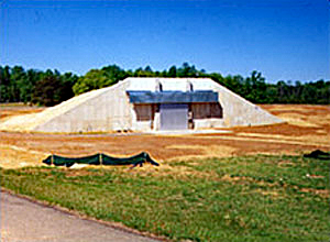
Earth Covered Magazine (ECM) structures are built to store AE. They are not designed to resist the damaging effects from an internal explosion, although they can effectively contain the effects from an explosion of very small AE quantities. ECMs are designed to protect their contents and prevent propagation of an explosion that may occur in an adjacent magazine. Proper siting of an ECM, from other Potential Explosion Sites (PES) and Exposed Sites (ES) including operations buildings, piers, aboveground magazines, rail sidings, classification yards, etc, ensures against unacceptable damage and injuries in the event of an accidental explosion.
Facilities are sited from a PES using the appropriate Explosive Safety Quantity- Distance (ESQD) relationship and based upon the Net Explosive Weight (NEW) at the PES.
Explosive safety standards that implement the DoD standards are contained in the following:
ECM designs fall within three basic structural hardness classifications; "7-Bar", "3-Bar" and "Undefined" depending upon the relative ability to resist blast loadings. The DDESB has established design criteria for each of the ECM classifications, and approved the classification of previously designed ECMs. DDESB Technical Paper (TP) 15 summarizes the development of AE storage facilities and documents approved protective construction designs.
Approved ECM designs may be site-adapted or tailored to the requirements of a specific site. Site specific tailoring primarily involves adapting the foundation and the drainage system to suit local soil and site characteristics. In addition, certain AE may require additional consideration for utilities, security, electrical, grounding, or humidity and temperature limits.
Any changes to approved designs, other than minimal site adaptation, that in any way may affect the explosive safety of the magazine design will not be used for construction without coordination and approval from the appropriate design agency and from the DDESB.
"7-Bar" (Standard) Designs A 7-Bar ECM provides the highest level of blast resistance and allows the use of the least restrictive siting separation distances. These designs may store up to 500,000 pounds NEW of hazard division 1.1, however some approved designs are based upon a lower storage capacity.
"3-Bar" Designs The headwall and doors of a 3-Bar ECM provides a lower level of blast resistance than a 7-Bar ECM resulting in more restrictive siting separation distances. A 3-Bar ECM may store up to 500,000 pounds NEW of hazard division 1.1, however some approved designs are based upon a lower storage capacity.
"Undefined" (Nonstandard) Designs An Undefined ECM provides the lowest level of blast resistance and requires the greatest siting separation distances. An Undefined ECM may store up to 500,000 pounds NEW of hazard division 1.1, however many of the designs are based upon a lower storage capacity.
Siting criteria for ECMs has been developed by the DDESB to define the minimum required separation distances between an ECM as a PES and ES that would be impacted from an accidental explosion. Minimum separation distances have been established between ECM and other magazines, operating buildings, inhabited buildings, and public traffic routes to ensure uniform minimum explosive safety standards for DoD facilities. Minimum separation distances are determined by the level of protection mandated by the applicable explosive safety standard, the ECM classification, the ES type, the quantity and type of AE within a PES, the physical orientation between the PES and the ES and the potential presence of barricading.
For most PES—ES orientations involving an ECM, it can be generally stated that the required siting separation distances are typically greater for a 3-Bar than a 7-Bar ECM and greater still for an Undefined ECM.
Plans for ECM projects must be reviewed and approved by the DDESB to ensure that minimum DoD explosive safety considerations have been addressed. Situations requiring approval include:
If pre-approved ECM designs are used, the project site plan along with the drawing numbers of the ECM design must be submitted for approval.
All new 7- and 3- Bar ECM designs must be approved by the DDESB before they can be used. The approval will require the submission of test results and/or detailed structural calculations.
All new Undefined ECM designs require approval from the DDESB to ensure minimum design and construction criteria are met.
For a description of the minimum requirements to validate explosive safety protective construction see the Department of Defense Explosives Safety Board Memorandum DDESB-PD , dated 21 October 2008.
Previous ECM designs have been grouped into four categories described by the following tables. The tables include information related to the design of the magazines including size and maximum stowage capacity. Only the designs within the first category, Table 1, are pre-approved as 7- or 3- Bar ECM Designs for new construction. The source of these tables is DDESB TP 15.
An individual summary page for each of the approved magazine designs is linked from Table 1. Electronic drawing files in PDF format are also provided along with additional information, if available, including guide specifications, AutoCAD or Micro Station drawings that can be downloaded and tailored for site-specific conditions, DDESB approval letters, and other relevant data.
Table 1—7-Bar and 3-Bar ECM Approved for New Construction—The content of this category identifies all 7-Bar and 3-Bar ECM currently approved by the DDESB for new construction. Notes are provided to identify those ECM that have NEW limitations and/or restriction associated with their approval.
Table 2—7-Bar and 3-Bar ECM No Longer Used for New Construction, But Still in Use—The content of this category identifies all ECM designs that previously have been approved for 7- and 3-Bar siting by the DDESB, but are no longer approved for use for new construction. In most cases, these designs have not been updated to satisfy current criteria. The primary intent of this table is to assist activities in siting existing magazines. NEW limitations and/or restrictions associated with their DDESB approval must be observed. These design drawings may be used as the basis for new ECM designs, but they must not be constructed until they are updated to comply with current explosive safety requirements, current construction methods and criteria, and are reviewed and approved by the DDESB. Approved updated design drawings shall clearly identify all changes made to the original design.
If ECM designs from this table are of interest to an activity as new construction, their use must be coordinated with the DDESB to ensure acceptability prior to initiating a project.
Table 3—Undefined Earth-Covered Magazines—The content of this category contains ECMs that have not been shown by analysis or testing to be capable of withstanding 7-bar or 3-bar loading. An Undefined ECM is permitted to store up to 500,000 pounds NEW of hazard division 1.1 unless noted otherwise in the table.
An undetermined ECM can be structurally analyzed in accordance with the Joint Service Manual TM5-1300/NAVFAC P-397/AFR 88-22 to determine its structural capabilities. Upon approval of the structural analysis supporting the magazine classification by the DDESB, the ECM design classification may be upgraded. For a listing of Undefined ECM designs see Table AP1-3 of DDESB Technical Paper (TP) 15
Table 4—Magazines (Earth-covered and Aboveground) and Containers that have reduced net explosives weight (NEW) and/or reduced quantity-distance (QD)—The contents of this category lists a number of AE storage structures and containers that have been approved by the DDESB for specific NEW and/or reduced QD. These items were generally designed for a particular application; however, as approved items, they can be used for other applications, providing all conditions, restrictions, design elements, etc., are observed. All documentation pertaining to the use of the storage structure or container must be obtained prior to their use. Table AP1-4 of TP-15 identifies restrictions or conditions for the use of these magazines or containers.
A semicircular arch or oval arch constructed of reinforced concrete or steel, or a combination of the two. It could also be a reinforced concrete box-type design.
A reinforced concrete floor slab that is typically sloped for drainage.
A reinforced concrete rear wall.
Design blast loads apply to headwalls of 7- and 3-bar ECM and to the roof of box-type magazines.
A reinforced concrete headwall that extends at least 2-1/2 feet above the top of the roof. The headwall is designed to withstand the blast pressures and impulses that will be experienced as a result of an explosion in an adjacent AE storage facility. This is a critical feature that is directly associated with the strength designation assigned to an ECM.
Heavy steel doors in the headwalls (either manually operated or motorized). Approved box-type ECM may have as many as five of these doors in their headwall. Doors are either of the swinging doors or sliding type. Sliding doors are generally used on the larger ECM, while swinging doors are primarily used on smaller ECM. Doors are designed to withstand the dynamic forces from an explosion in an adjacent AE storage facility, and are therefore, a critical element of an ECM design.
Earth cover over the top, sides, and rear of the ECM. A minimum of 2 feet (24 inches) of earth cover is required over the ECM.
Reinforced concrete wingwalls on either side of the headwall. The wingwalls may slope to the ground or may join wingwalls from adjacent ECM. The purpose of wingwalls is to retain the earth fill along the side slopes of the ECM.
Lightning protection and grounding systems. Reinforcing steel in the walls, floor, and roof must be electrically continuous to provide electrical bonding between the elements and produce a faraday-like shield. Techniques commonly used and approved in the construction industry to join reinforcing steel are acceptable. The steel arch of an ECM must be similarly joined to the reinforcing steel in the floor. Minimum resistance valves apply. Other metal masses, such as ventilators, shall also be grounded and connected to a common earth electrode system such as a buried ground girdle.
Incoming utilities are installed to meet the material, installation, grounding, and lightning surge protection criteria.
When required, internal electrical work and equipment must be rated for the hazardous environments expected within the ECM.
In the case of a box-type ECM, the walls and roof may be constructed of reinforced concrete or of prefabricated concrete panels that are assembled in the field. Earth cover, lightening, and grounding criteria described above also applies to box-typed ECM.
Listed below are the descriptions of the cross-section of magazines.
Arch—Also known as a circular arch. A single radius is used to define the interior face of the arch, which may be constructed of reinforced concrete, steel (corrugated, laminated, or single gage), or a combination of reinforced concrete and steel to form a composite arch (steel interior arch with overlying concrete).
Arch, Oval—This arch is in the shape of an oval, with the lower portion of each sidewall bowing in towards the direction of the centerline. The arch can be constructed of steel, reinforced concrete, or a composite of both. The shape is defined by the use of a single radius for the majority of the arch, with a separate radius called out for the lower portions of the arch. The modified FRELOC-Stradley ECM design is an example of an oval-arch ECM.
Arch, Semi-Circular—The sidewalls are elongated with the arch defined by a radius that originates approximately 3 to 5 feet above floor level. A radius originating at the opposite sidewall defines the lower portion of the arch. The arch can be constructed of either reinforced concrete or steel.
Stradley—This reinforced concreted ECM is characterized by vertical sidewalls that blend into the arched roof. Three radii are used to define the arch and the transition from the vertical sidewalls to the roof arch. Another feature of the Stradley ECM is that its walls are significantly thicker at the base of the sidewalls and thinner at the crown of the arch. There are currently no Stradley designs approved for new construction.
FRELOC-Stradley—The FRELOC-Stradley ECM is constructed of reinforced concrete. Its interior shape is similar to a Stradley ECM, except that the sidewalls and arch have the same thickness.
Modified FRELOC-Stradley—This ECM design was the first ECM constructed with an oval arch. See the information above for the oval arch. There are currently no Modified FRELOC Stradley designs approved for new construction.
Box—This term describes any ECM that has an internal box shape. Explosives limits can range from less than a pound NEW of hazard division 1.1 to 500,000 pounds NEW hazard division 1.1.
Dome—The domed shape is used for only the Corbetta ECM design. The interior wall is approximately three times the height of the magazine. There are currently no Dome designs approved for new construction.
The selection of an ECM is based primarily on the type and quantity of AE that will be stored in the magazine and the cost of construction. Siting restrictions, potential operational considerations, AE compatibility, and other considerations may also factor in the selection of the magazine.
Individual summary sheets for each of the approved 7- and 3- Bar ECM designs within Table 1 are provided to help in the selection process. The information provided in the summary sheets include the physical dimensions of the magazine, approved drawing number, number and size of doors, maximum NEW storage capacity, and comments related to the use of the design.
Individual services may also provide additional guidance on the selection of magazine designs.
Suggested storage layout plans for various AE within many of the approved magazine designs are available to assist in the effective use of the magazine and as a tool to estimate the potential stowage capacity. The U.S. Army Technical Center of Explosives Safety (USATCES) develops and maintains several tools and documents related to the storage of AE.
Barricades are protective structures that can act as a barrier between a PES and an ES. When properly sited and constructed they are an effective protection against low angle fragments and for reducing shock overpressures near the barricade. To protect against low angle fragments barricades must be high enough to intercept the ballistic trajectories of fragments and thick enough to reduce the fragment velocity to acceptable levels.
Army Definitive Drawings for Barricades Standard Design (Drawing Code DEF 149-30-01) illustrates several conceptual barricade designs utilizing various construction materials. For additional information see DoD Explosives Safety or the applicable service explosive safety standards.
The content of this category identifies all 7-Bar and 3-Bar ECM currently approved by the DDESB for new construction. Notes are provided to identify those ECM that have NEW limitations and/or restrictions associated with their approval.
Select a drawing number to view and download files associated with that ECM.
These documents are available in the following formats: Adobe Acrobat (PDF) | CAD in compressed ZIP | DWG
Description | Drawing Number | Dimensions | Door Opening | Weight |
|---|---|---|---|---|
Type G Box ECM Standard Drawings | 14145654 through 14145739 | 94'-8" Wide x 50'-0" Long x 14'-9.75" (Rear) To 15'-10" (Front) High | (3) Sliding 26'-0" Wide x 11'-0" High | 500,000lb |
Approved Files for UseDocumentationComments/Design ConsiderationThe Type G Box ECM has been designed for the storage of munitions. The design of this structure was based on the design of the existing Navy Type C Box ECM, updated to comply with current design criteria, address operational issues noted in previous designs, and improve overall ability to support the Navy explosive storage needs moving forward. Due to the comprehensive nature of the updates to the Type C Box magazine, it has been completely redesigned and renamed the Type G Box magazine. The interior horizontal dimensions of the Type G are the same as the Type C. The clear height, from floor to ceiling, at the front interior space is the same as the Type C, however the roof slope was decreased which increases the clear height, from floor to ceiling, at the rear of the interior space. The columns and door openings have been shifted slightly to promote symmetry, ease of construction, and better efficiency. The exterior walls are thicker, and a mat slab design was used for the foundation. Mechanical rooms were included as site adapt options. The pilasters and header beams have been reconfigured to better absorb and dissipate blast hazards in a detonation scenario, and the blast door includes enhanced physical security features, an automated trench plate lifting system, and a bottom-supported wheel and rail system. 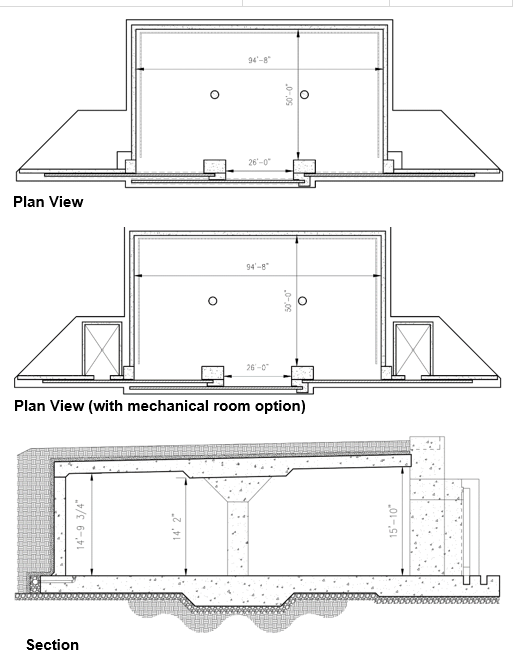 | ||||
Type H Box ECM Standard Drawings | 14138777 through 14138861 | 158'-8" Wide x 50'-0" Long x 14'-9.75" (Rear) To 15'-10" (Front) High | (5) Sliding 26'-0" Wide x 11'-0" High | 500,000lb |
Approved Files for UseDigital DrawingsDocumentationComments/Design ConsiderationThe Type H Box ECM has been designed for the storage of munitions. The design of this structure was based on the design of the existing Navy Type D Box ECM, updated to comply with current design criteria, address operational issues noted in previous designs, and improve overall ability to support the Navy explosive storage needs moving forward. Due to the comprehensive nature of the updates to the Type D Box magazine, it has been completely redesigned and renamed the Type H Box magazine. The interior horizontal dimensions of the Type H are the same as the Type D. The clear height, from floor to ceiling, at the front interior space is the same as the Type D, however the roof slope was decreased which increases the clear height, from floor to ceiling, at the rear of the interior space. The columns and door openings have been shifted slightly to promote symmetry, ease of construction, and better efficiency. The exterior walls are thicker, and a mat slab design was used for the foundation. Mechanical rooms were included as site adapt options. The pilasters and header beams have been reconfigured to better absorb and dissipate blast hazards in a detonation scenario, and the blast door includes enhanced physical security features, an automated trench plate lifting system, and a bottom-supported wheel and rail system. 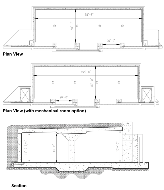 | ||||
Single Bay CLWS Navy ECM Standard Drawings | 12905820 through 12905870 | 119'-0" Long x 32'-0" Wide | 32'-0" Wide x 14'-0" High | 500,000lb |
Approved Files for UseComments/Design ConsiderationThese drawings represent the single bay configuration of the Containerized Long Weapons Storage (CLWS) Navy Earth Covered Magazines, approved by DDESB on 25 July 2024. All new construction of single bay CLWS Magazines will be in accordance with drawings 12905820 through 12905870. The Single Bay CLWS ECM is a cast-in-place reinforced concrete box magazine 32 ft-wide. The magazine can be built 95'-6" or 119' long and has a minimum interior height of 24'-8", with a transverse roof slope of 1/4" per foot. The roof, side and rear walls, and headwall of the magazine consist of 24" thick concrete walls. The blast door of the magazine consists of a single sliding steel door, spanning vertically between a bottom trench and a header beam, covering a 14-ft tall, 32-ft wide opening. This header beam frames into pilasters located at the intersection of the headwall and sidewalls. The blast door includes enhanced physical security features, an automated trench plate lifting system, and a bottom-supported wheel and rail system. | ||||
Double Bay CLWS Navy ECM Standard Drawings | 12914696 through 12914757 | 114'-0" Long x 50'-0" Wide x (minimum) 24'-7 1/2" high | 32'-0" Wide x 14'-0" High | 500,000lb |
Approved Files for UseComments/Design ConsiderationThese drawings represent the double bay configuration of the Containerized Long Weapons Storage (CLWS) Navy Earth Covered Magazines, approved by DDESB on 26 January 2025. All new construction of double bay CLWS Magazines will be in accordance with drawings 12914696 through 12914757. The Double Bay CLWS ECM is a novel reinforced concrete box-type design with two bays separated by an interior reinforced concrete wall. Each bay has clear interior dimensions of 114'-0" length by 50-'0" width by minimum 24'-7 1/2" height. The front wall of each bay has a door opening with clear dimensions of 32'-0" width by 14'-0" height. The design also includes optional interior bridge crane and two mechanical rooms for environmental controls. | ||||
Navy Modular Storage Magazine Version 2 | 14148449 through 14148533 | 25'-0" Wide x 81'-6" Long x 14'-8" High | (1) Sliding | 500,000lb |
Approved Files for UseComments/Design ConsiderationThese drawings represent the new design of Navy Modular Storage Magazine (MSM) Version 2, approved by DDESB on 28 April 2025. All new construction of MSMs will be in accordance with drawings 14148449 through 14148533. | ||||
Navy Modular Storage Magazine | ||||
RC Box Type 'M' | ||||
RC Box Type 'C' | ||||
RC Box Type 'D' | ||||
RC Circular Arch | ||||
Composite Circular Arch | ||||
Composite Oval Arch | ||||
RC Box Type 'E' | ||||
RC FRELOC Stradley | (Korean Version) | 25'-0" Wide x 87'-0" Max. Length (normally length is 60' or 80') x 13'-0" (Rear) High | (1) Sliding | 500,000lb |
Approved Files for UseComments/Design ConsiderationThis design is the latest approved version of the Republic of Korea Army (ROKA) drawing for 33-15-74. The original basis for the Korean version was U.S. Army COE 33-1-74. The Korean drawings assure that all reinforcing steel is electrically continuous. The previous version of this drawing was approved by the DDESB as a 7-bar magazine on 25 May 2002.  | ||||
RC FRELOC Stradley | (Modified Korean Version) | 25'-0" Wide x 87'-6" Max. Length (normally length is 60' or 80') x 13'-0" (Rear) High | (1) Sliding | 500,000lb |
Approved Files for UseComments/Design ConsiderationThis design is a modified version of the Republic of Korea Army (ROKA) drawing for 33-15-74. The original basis was U.S. Army COE 33-1-74. The Korean drawings assure that all reinforcing steel is electrically continuous. The Modified version includes provisions for air conditioning the magazine. The original version of this drawing was approved by the DDESB as a 7-bar magazine on 25 May 2002.  | ||||
Steel, Semi-Circular Arch | 421-80-01 | Approx. 26'-0" Wide x 19'-0" Min. expandable up to most commonly used 89'-0" Length x 14'-0" (Max.) High | (1) Sliding | 500,000lb |
Approved Files for UseNone at this time. Comments/Design ConsiderationUnder Army Review, Not Approved for New Construction If a steel arch ECM is required, use standard drawings 421-80-03, Steel Oval Arch. Contact HNC and USATCES for additional guidance on appropriate site adapt of the 421-80-03 standard.  | ||||
Steel Oval Arch | 421-80-03 | 28'-2" (Max.) Wide x 21'-0" Min. to 89'-0" Max. Length x 14'-11" (Max.) High | (1) Sliding | 500,000lb |
Approved Files for UseComments/Design ConsiderationReplaced 33-15-73. Arch design composed of a 1-gauge (0.280 inch) corrugated steel arch. The site-adapt Designer of Record shall ensure DoD and Army explosives safety requirements for Lightning Protection and Grounding are met. The Designer of Record shall obtain review support and technical concurrence of the site-adapt design from the U.S. Army Corps of Engineers Engineering and Support Center, Huntsville.  | ||||
RC Arch | 421-80-05 | 26'-7 1/4" Wide x 90'-0" Max. Length (normally length is 60' or 80') x 14'-0" (Rear) High | (1) Sliding | 500,000lb |
Approved Files for UseDigital Drawings
DocumentationComments/Design ConsiderationConstructed using the Techspan Precast Concrete System, developed by the Reinforced Earth Company, for each construction. The headwall and door are derived for 33-15-74.  | ||||
RC Box | 421-80-07 | 25'-0" Wide x 20'-0" Min. to 80'-0" Max. Length x 11'-0" High | Hinged | 500,000lb |
Approved Files for UseDigital Drawings
DocumentationComments/Design ConsiderationMSM Standard 421-80-07 replaces the previous MSM Standard 421-80-06 (modified). The new series updates the drawings to meet current AEC CAD standards, improved plan readability, constructability, and correct omissions within the construction drawings. Another key element performed during the revision was the incorporation of lessons learned from previous MSM projects at various user organizations. In addition to the drawings, a conventional structural load analysis was performed to identify some key loading limits, which will assist the designer during the site-adaption process.  | ||||
Modular Storage Magazine, Box-Type | 421-80-08 | 25'-0" Wide x 20'-0" Min. to 80'-0" Max. Length x 14'-8" High | Hinged | 500,000lb |
Approved Files for UseDigital Drawings
DocumentationComments/Design ConsiderationThe MSM Box-Type Standard 421-80-08 replaces the previous Munitions Storage Magazine (14 feet ceiling height) as designed for Hill AFB. The new series updates the drawings to meet current AEC CAD standards, and features improved plan readability, constructability, and corrects omissions within the construction drawings. Another key element performed during the revision was the incorporation of lessons learned (see Appendix of Design Narrative) from previous MSM projects at various user organizations. In addition to the drawings, a conventional structural load analysis was performed to identify some key loading limits, which will assist the designer during the site-adaption process.  | ||||
ECM, Concrete Oval-Arch | 421-80-09 | 25'-0" Wide x 90'-0" Max. Length (normally length is 60' or 80') x 14'-0" (Rear) High | (1) Sliding | 500,000lb |
4Approved Files for UseDigital Drawings
DocumentationComments/Design ConsiderationCOE Standard 421-80-09 replaces the previous COE Standard 33-15-74. The new series updates the drawings to meet current AEC CAD standards, improves plan readability, constructability, and corrects omissions within the construction drawings. Headwall components have been re-analyzed under the 7-bar blast loading from DoD 6055.09-M using the methodology of UFC 3-340-02. The remaining components are as originally designed. In addition to the drawings, a conventional structural load analysis was performed to identify some key loading limits, which will assist the designer during the site-adaption process and a new retaining wall design was completed to simplify construction of the wing walls. The documentation will not include specifications.  | ||||
USACE Modular Storage Magazine Box–Type Flow–Thru | 421-80-10 | (internal): x 4470mm High | (2) Hinged | 500,000lb |
Approved Files for Use | ||||
USACE Modular Storage Magazine Box–Type European Version | 421-80-13 | (internal): x 4470mm High | (1) Sliding | 500,000lb |
Approved Files for Use | ||||
RC Box Type 'D' | 6448555 through 6448588 | 158'-8" Wide x 50'-0" Long x 13'-8" (Rear) To 15'-10" (Front) High | (3) Sliding | 500,000lb |
Approved Files for UseComments/Design ConsiderationUnder Navy Review. Contact NAVFAC LANT, Code CI42 This design is identical to NAVFAC 6448522 through 6448554, Box Type D, except that it incorporates a High Security Integrated Locking System (HSILS).  | ||||
RC Box Type 'F' | ||||
RC Box | Munitionslagerhause | |||
Steel Oval Arch | Munitionslagerhause | |||
RC Box | Munitionslagerhause | |||
Steel Oval Arch | Munitionslagerhause | |||
The content of this category identifies all ECM designs that previously have been approved for 7- and 3-Bar siting by the DDESB, but are no longer approved for use for new construction. In most cases, these designs have not been updated to satisfy current criteria. The primary intent of this table is to assist activities in siting existing magazines. NEW limitations and/or restrictions associated with their DDESB approval must be observed. These design drawings may be used as the basis for new ECM designs, but they must not be constructed until they are updated to comply with current explosive safety requirements, current construction methods and criteria, and are reviewed and approved by the DDESB. Approved updated design drawings shall clearly identify all changes made to the original design.
If ECM designs from this table are of interest to an activity as new construction, their use must be coordinated with the DDESB to ensure acceptability prior to initiating a project.
Select a drawing number to view and download files associated with that ECM.
These documents are available in the following formats:
Adobe Acrobat (PDF) | CAD in compressed ZIP
| Description | Drawing Number | Relationship to Other Drawings | ||||||||||||||||
|---|---|---|---|---|---|---|---|---|---|---|---|---|---|---|---|---|---|---|
| Steel Arch | 1059128-1059130 Modifications 1059132, 1069906, 1355460 and 1355461 | Reference 1351905 | ||||||||||||||||
Reference Information - Steel Arch
Digital Drawings
Comments/Design ConsiderationThere is no reduced ESQD associated with this ECM design. |
||||||||||||||||||
| RC Box, Type 'A' | 1404000-1404007 | Supersedes 749771-749774 and 793751 | ||||||||||||||||
Reference Information - RC Box, Type 'A'
Comments/Design ConsiderationSupersedes Drawings 749771-749774 and 793751. NAVFAC MIL-BUL-340 (YD), Jul 93, lists these ECM drawings as canceled. |
||||||||||||||||||
| RC Box Type 'B' | 1404018-1404025 and 952132-952134 | Supersedes 952127-952131 and 952135 | ||||||||||||||||
Reference Information - RC Box Type 'B'
Comments/Design ConsiderationSupersedes Y & D Drawings 952127-952131 and 952135. NAVFAC MIL-BUL-340 (YD), Jul 93, lists these ECM drawings as canceled. |
||||||||||||||||||
| RC Box Type 'C' | 1404430-1404444 | Superseded by 14004689-14004720 and 14005091-14005122 | ||||||||||||||||
Reference Information - RC Box Type 'C'
Comments/Design ConsiderationDDESB approval signature of 11 May 85 on drawings. Replaced by RC Box, Type 'C' - NAVFAC 14004689-14004720 (Without Platform) and NAVFAC 14005091-14005122 (With Platform) |
||||||||||||||||||
| RC Box Type 'C' | 14004689-14004720 and 14005091-14005122 | Superseded by 14004689-14004720, Rev. 1 and 14005091-14005122, Rev. 1 | ||||||||||||||||
Reference Information - RC Box Type 'C'
Digital Drawings
DocumentationComments/Design ConsiderationDDESB approval signature of 04-Jan-2011 on drawings. Replaced by RC Box, Type 'C' - NAVFAC 14004689-14004720, Rev. 1 (Without Platform) and NAVFAC 14005091-14005122, Rev. 1 (With Platform) |
||||||||||||||||||
| Steel Oval Arch | 1404026-1404034 | |||||||||||||||||
Reference Information - Steel Oval Arch
Comments/Design ConsiderationListed in DDESB minutes as STD magazine. NAVFAC MIL-BUL-340 (YD), Jul 93, lists these ECM drawings as canceled. |
||||||||||||||||||
| Steel Arch | 1404328-1404342 | Supersedes 1059128-1059130, 1059132, 1069906 and 1355460-1355461 | ||||||||||||||||
Reference Information - Steel Arch
Digital Drawings
|
||||||||||||||||||
| RC Box, Type 'D' | 1404465-1404478 | Superseded by 6448522-6448554 and 6448555-6448588 | ||||||||||||||||
Reference Information - RC Box, Type 'D'
DocumentationComments/Design ConsiderationDDESB (P. Price) approval signature of 05 Nov. 85 on drawings. Sited for 350,000 pounds NEW. Superseded by NAVFAC Drawings 6448522-6448554 (Standard Box Magazine Type D) and NAVFAC Drawings 6448555-6448588 (HSLIS Box Magazine Type D), both dated 27 May 97. |
||||||||||||||||||
| RC Box, Type 'D' | 6448522-6448554 | Superseded by 14021368-14021404 and 14021406-14021444 | ||||||||||||||||
Reference Information - RC Box, Type 'D'
Digital DrawingsDocumentationComments/Design ConsiderationSuperseded NAVFAC 1404465 through 1404478. DDESB approval signature of 30 June 87 on original drawings. Replaced by RC Box, Type 'D' - NAVFAC 14021368-14021404 (Without Platform) and NAVFAC 14021406-14021444 (With Platform) |
||||||||||||||||||
| RC Box, Type 'D' | 14021368-14021404 and 14021406-14021444 | Superseded by 18232899-18232936 and 18232939-18232978 | ||||||||||||||||
Reference Information - RC Box, Type 'D'
Digital Drawings
DocumentationComments/Design ConsiderationSuperseded NAVFAC 6448522 through 6448554. DDESB approval signature of 13 March 13 on original drawings. Replaced by RC Box, Type 'D' - NAVFAC 18232899-18232936 (Without Platform) and NAVFAC 18232939-18232978 (With Platform) |
||||||||||||||||||
| RC Box, Type 'F' | 1404541-1404555 | Superseded by 6448589-6448621 | ||||||||||||||||
Reference Information - RC Box, Type 'F'
Comments/Design ConsiderationSuperseded by NAVFAC Drawings 6448589-6448621. This magazine design was sited for 350,000 pounds NEW. A site specific approval was granted to Naval Weapons Station, Seal Beach, for the construction of four Box Type F Magazines with the dehumidification system located on top of the Magazine, vice behind the magazines as was shown on the approved design drawings. This modification was not approved by the DDESB as a standard design, since the Navy never came in with a modified standard magazine drawing set to incorporate the addition of the dehumidification system onto the magazine roof. |
||||||||||||||||||
| RC FRELOC Stradley | 219-25-321 | Based on 33-15-74 | ||||||||||||||||
Reference Information - RC FRELOC Stradley
Digital DrawingsComments/Design ConsiderationThis design was constructed at Luke AFB. It was evaluated by the COE, Huntsville, to determine its structural rating. Their analysis, documented on memo CEHNC-ED-CS-S(210.2b) of 23 January 2002, found that the design shown on the drawings came from existing 7-Bar ECM design 33-15-74. |
||||||||||||||||||
| RC Stradley | 33-03-0028 | Based on 33-15-61 | ||||||||||||||||
Reference Information - RC Stradley
Comments/Design ConsiderationThis design was constructed at Osan Air Base, Korea and is based on OCE Drawing 33–15-61, 30 Dec, 1959, which is considered a 7-Bar ECM. The drawings provides for two different ECM designs. One design is a typical ECM with a single headwall and the ventilator out the rear of the ECM, while the second design includes two headwalls and a ventilator that is centered on the roof of the ECM. Based on a review by the Huntsville COE, the headwall and doors used on 33-03-0028 match the headwall and doors of 33-15-61. The doors of the three designs are all 6-foot wide sliding doors. Two of these doors are required per entrance. |
||||||||||||||||||
| RC FRELOC Stradley | 33-03-31 | Similar to 33-15-61 | ||||||||||||||||
Reference Information - RC FRELOC Stradley
Comments/Design ConsiderationThis design is similar to 33-15-61, the DDESB approved Standard Freloc-Stradley Magazine. 3-03-31 was designed for construction at VILSECK ASP-I (Germany) for USAFE. It measured 26' W X 80' L and had a ceiling height of 14' at the centerline. The entrance measured approximately 10' by 10'. It had a reinforced concrete arch of uniform thickness. a heavily reinforced headwall, and bi-parting, double-leaf steel doors. A Sep 1977 dynamic analysis of this Freloc design, performed by Agbabian Associates for the COE, European Division, determined that the headwall was sufficiently strong to meet NATO face-on loading criterion, but the door was not. Recommendations were prodded in Agbabian Associates Report R-7745-4503 to strengthen the doors by adding additonal horizontal and vertical stiffeners on the exterior side of the doors. DDESB-KT Memos of 27 Jan and 4 May 1978 states that the door of the ECM analyzed by Agbabian Associates (33-03-31) met U.S. standard magazine criteria. |
||||||||||||||||||
| RC Arch | 33-03-43 | Compared to 33-15-61 and 33-15-64 | ||||||||||||||||
Reference Information - RC Arch
Comments/Design ConsiderationKnown as a Quick Reaction Site (QRS) magazine, which were only constructed in Germany. Permitted to store a maximum of 4,000 kg NEQ. DDESB-KT Memo of 19 March 1976 evaluated this design and compared its structural components to counterpart features of standard ECM, particularly those in 33-15-61 and 33-15-64, which had undergone extensive testing. Based on this review, the design was approved for she storage of 4,000 kg NEQ in each arch unit. In addition, the design of the door was considered to qualify the ECM design for the minimum separation distances permitted. |
||||||||||||||||||
| RC Stradley | 33-13-02 | Revision of 33-15-06 | ||||||||||||||||
Reference Information - RC Stradley
DocumentationComments/Design ConsiderationA COE, Huntsville District, letter of 13 Apr 98 determined this ECM was a revision of 33-15-06 (a 7-Bar ECM) and recommended it be considered a 7-Bar ECM as well. A 26 Jan 99 DDESB letter approved use of ECM constructed in accordance with Drawing 33-13-02, as a 7-Bar magazine. A provision of the approval was that the separation distances between the rear or side of these ECMs, as the PES, to the front of one of these ECMs, as an ES, was at least 360 feet. Side to side exposures between the PES and the ES are required to be separated in accordance with the appropriate entries for either 3-bar or 7-bar ECMs in accordance with Table 9-5 of DoD 6055.9-ST:). |
||||||||||||||||||
| RC Stradley | 33-15-01 | Consistent with AW33-15-01 | ||||||||||||||||
Reference Information - RC Stradley
Digital Drawings
Comments/Design ConsiderationA double-headwall (flow-through) design with a single sliding door on each headwall. The headwall and door design are consistent with the COE, Omaha District. ALCM magazine design (AW 33-15-01), a 7-Bar design. |
||||||||||||||||||
| RC Stradley | AW33-15-01 | |||||||||||||||||
Reference Information - RC Stradley
Digital DrawingsDocumentationComments/Design ConsiderationThis design was known as the Air Launched Cruise Missile (ALCM) Igloo and is a double-headwall (flow-through) design with two large sliding doors on each headwall. The design provides 7-Bar protection. A 26 Feb 1980 DDESB letter approved AW 33-15-01 as a typical layout for ALCM storage and considered this design equal to a standard ECM. There are two designs in existence, with the only differences being the footings and floor slab. The initial design constructed at Griffis AFB, NY, had wall footings and a floating slab-on-grade. The subsequent design revised the foundation and flooring to a mat foundation slab. The subsequent design is believed to have been constructed at the following Air Force Bases: Grand Forks, ND. Minot. ND: Fairchild, WA. Ellsworth.. SD: Wurtsmith, WI; K.I. Sawyer, MI; Barksdale. LA; Blythville. AR: McConnel.. KS: Carswell, TX; and Andersen, Guam. Internal dimensions are 40' wide by 112' long by 18'6" high along the longitudinal centerline. Each of the sliding doors measures 18' 10" long by 13'7 5/8" high. |
||||||||||||||||||
| RC Arch | AW33-15-02 | |||||||||||||||||
Reference Information - RC Arch
Comments/Design ConsiderationConstructed at Luke AFB, analyzed by COE- Huntsville, to determine its Structural rating. Their analysis, documented on memo CEHNC-ED-CS-S (210-2b) of 23 January 2002, found that the design of the headwall and door meets 7-Bar criteria. |
||||||||||||||||||
| Steel, Oval Arch | 33-15-02 | |||||||||||||||||
Reference Information - Steel, Oval Arch
Digital DrawingsComments/Design ConsiderationA double-headwall (flow-through) design with a single sliding door on each headwall. The headwall and door design are consistent with the COE, Omaha District, ALCM magazine design (AW 33-15-01), a 7-Bar design. |
||||||||||||||||||
| RC Arch | 33-15-02 | |||||||||||||||||
Reference Information - RC Arch
Comments/Design ConsiderationConstructed at Barkesdale AFB, LA. Analyzed by COE, Huntsville AL, to determine structural rating. Their analysis, documented on memo CEHNC-ED-CS-S of 15 July 2003 found that the design of the headwall and doors met 7-Bar criteria. |
||||||||||||||||||
| RC Stradley | 33-15-03 | Similar to 33-15-01 | ||||||||||||||||
Reference Information - RC Stradley
Digital DrawingsComments/Design ConsiderationA double-headwall (flow-through) design with a single sliding door on each headwall. The headwall and door design are consistent with the COE. Omaha District ALCM magazine design. Similar design to Omaha District 33-15-01, but with a larger door opening. |
||||||||||||||||||
| Steel Oval Arch | 33-15-04 | Similar to 33-15-02 | ||||||||||||||||
Reference Information - Steel Oval Arch
Comments/Design ConsiderationA double-headwall (flow-through) design with a single sliding door on each headwall. The headwall and door design are consistent with the COE, Omaha District ALCM magazine design. Similar design to Omaha District 33-15-02, but with a larger door opening. |
||||||||||||||||||
| RC Arch | 33-15-06 | Previously called the "YURT" Magazine, this design Superseded drawings 652-686 through 652-693 and 33-15-01 | ||||||||||||||||
Reference Information - RC Arch
Digital DrawingsComments/Design ConsiderationPreviously called the "YURT" Magazine. This magazine design superseded Drawings 652-686 - 33-15-01. A 1 Apr 87 Huntsville Division, COE, letter stated that ECM design 33-15-06 was no longer being used for new construction. ECM separation distances based in the following criteria: Side to side - use 1.5W" 1/3; back to back - 1.5W 1/3; front to back - 4.5W 1/3 |
||||||||||||||||||
| RC FRELOC Stradley | 33-15-13 | |||||||||||||||||
Reference Information - RC FRELOC Stradley
Digital DrawingsComments/Design ConsiderationA 4 May 78 DDESB letter restated that 33-15-13 was a standard ECM and that variations of this design were acceptable, provided new designs were at least equal to it structurally. This design is known as the "thin-wall" magazine and is known to have been built at Camp Darby, Italy. Similar designs, based on the 33- 15-13 design are known to have been constructed in Germany and elsewhere. |
||||||||||||||||||
| Modified FRELOC Stradley (Steel Oval Arch) | 33-15-15 | |||||||||||||||||
Reference Information - Modified FRELOC Stradley (Steel Oval Arch)
Digital Drawings
Comments/Design ConsiderationThis design includes a double leaf door system, similar to the 33-15-61 two-leaf sliding door tested as part of ESKIMO 11. |
||||||||||||||||||
| RC FRELOC Stradley | 33-15-16 | Also known as Type 16 Magazine Corrected deficiencies with 33-15-14 | ||||||||||||||||
Reference Information - RC FRELOC Stradley
DocumentationComments/Design ConsiderationAlso known as the "Type16" Magazine. This design corrected strength deficiencies found in ECM design 33-15-14, which was determined to be non-standard ECM. |
||||||||||||||||||
| Steel Arch | 33-15-208 | |||||||||||||||||
Reference Information - Steel Arch
Comments/Design ConsiderationReplaced design 33-15-28 that was previously approved by DDESB for construction at Larson Barracks, Kitzingen, GE. This design has only one entrance vice the 2 shown on 33-15-28. |
||||||||||||||||||
| Steel Arch | 33-15-28 | |||||||||||||||||
Reference Information - Steel Arch
Comments/Design ConsiderationConstructed at Larson Barracks, Kitzingen, GE. Based on QRS magazine. which were only constructed in Germany (see 33-03-43 design). This design had 2 front headwalls and doors and no rear wall. |
||||||||||||||||||
| RC Stradley | 33-15-58 | Replaced YT-1-1 through YT-111 Constructed in accordance with 33-15-58 and 33-15-61 | ||||||||||||||||
Reference Information - RC Stradley
Comments/Design ConsiderationApproved during 259th ASESB meeting of 14 Oct 70 and was considered to be atomic blast resistant. This drawing replaced former drawings YT -1 -1 though YT-111. At that meeting, the Chairman, ASESB, also read into the record that Stradley (Yurt) magazines which are constructed in accordance with Standard OCE Drawings 13-15-58 and/or 33--15-61 are considered to be equivalent in strength to the OCE's standard earth covered igloo magazines. |
||||||||||||||||||
| RC Stradley | 33-15-61 | Replaced YT-1-1 through YT-111 Constructed in accordance with 33-15-58 and 33-15-61 | ||||||||||||||||
Reference Information - RC Stradley
Digital DrawingsComments/Design ConsiderationApproved during 259th ASESB meeting of 14 Oct 70. This drawing replaced former drawings YT-1-1 though YT-111. At that meeting, the Chairman, ASESB, also read into the record that Stradley (Yurt) magazines which are constructed in accordance with Standard OCE Drawings 33-15-58 and/or 33-15-61 are considered to be equivalent in strength to the OCE's standard earth covered igloo magazines. Two door sizes are shown on the drawing: a 10' X 10' door and a 12'X 12' door- DDESB memo of 22 Apr 1980 discusses the successful testing of the two-leaf sliding door of 33-15-61 as pan of ESKIMO II. |
||||||||||||||||||
| RC Stradley | 33-15-61-6 | Similar to 33-15-61 | ||||||||||||||||
Reference Information - RC Stradley
Comments/Design ConsiderationVery similar to 33-15-61, which is a 7-Bar ECM. Only differences were the use of a 10' door and 3,000 psi concrete vice a 12' door and 2,500 psi concrete. Doors and headwall were analyzed and were found to meet 7-Bar criteria. COE Huntsville e-mail of 24 January 2003 to DDESB documents results of review and analysis. |
||||||||||||||||||
| N/A | 33-15-62 | Applies to 33-15-01, 33-15-06 ad 652-686 through 652-692 | ||||||||||||||||
Reference Information - N/A
Digital DrawingsComments/Design ConsiderationThis is not an ECM design drawing. This drawing permitted installation of larger doors on specific magazines, on the basis that the strength of the modified structures remained unchanged as a result of the door modifications. This drawing applied to ECM 33-15-01, 33-15-06 and 652-686 - 652-692. |
||||||||||||||||||
| Steel, Semi-Circular Arch | AW33-15-63 | |||||||||||||||||
Reference Information - Steel, Semi-Circular Arch
Comments/Design ConsiderationApproved during 225th ASESB meeting of 19 Feb 64 as a standard magazine design. A 1 Apr 87 COEHQ letter stated that ECM design AW 33-15-63 was no longer being used for new construction. Drawing AW 33-15-63 had two designs shown on it. One is a traditional magazine with a single 12-inch thick reinforced concrete headwall, while the second is a design with two headwalls and doors (flow through design) COE structural evaluation of AW 33-15-63 door in 2003 determined the door would not provide 7 or 3- Bar protection. The conversion of these designs from Standard magazines to 7-Bar magazines in the early 1990s was in error in that the hinged doors of AW 33-15-63, AW 33-15-64 and 33-15-65 (all similar door designs) are not capable of providing 7 or 3-Bar protection to their contents. This determination was arrived at during ESKIMO III, which tested a AW 33-5-64 design and by a structural analysis of the door design that was conducted by the Huntsville COE at the request of DDESB-KT. Paragraph C2.3.7.3. ESKIMO III, June 1974 provides further information regarding this test. If different doors than those shown of AW 33-15-63, AW 33-15-64, and 33-15-65 have been installed, then the headwall and alternate door(s) can be structurally evaluated to determine their strength. As a result of the ESKIMO series tests, services began moving towards single and bi-sliding doors or hardened headwall pilasters and header. Siting guidance: Do not use for new construction. Site existing magazines as Undefined structures to provide a higher level of protection to contents. Use of the K4.5 that is permitted for 7-Bar ECM (face-to-face) with intervening barricades or the K6 permitted for 7-Bar ECM (face-to-face) without a barricade provides a very high likelihood of prompt propagation between ECM designed to AW 33-15-63, AW 33-15-64 and 33-15-65. |
||||||||||||||||||
| Steel Arch | AW33-15-64 | |||||||||||||||||
Reference Information - Steel Arch
Digital DrawingsComments/Design ConsiderationApproved during 225th ASESB meeting of 19 Feb 64 as a standard magazine design. A 1 Apr 87 COEHQ letter stated that ECM design AW 33-15-64 was no longer being used for new construction. COE structural evaluation of AW 33-15-64 door In 2003 determined the door would not provide 7 or 3-Bar protection. The conversion of these designs from Standard magazines to 7-Bar magazines in the early 1990s was in error in that the hinged doors of AW 33-15-63, AW 33-15-64 and 33-15-65 (all similar door designs) are not capable of providing 7 or 3-Bar protection to their contents. This determination was arrived at during ESKIMO III, which tested a AW 33-5-64 design and by a structural analyses of the door design that was conducted by the Huntsville COE at the request of DDESB-KT. Paragraph C2.3.7.3. ESKIMO III, June 1974 provides further information regarding this test. If different doors than those shown of AW 33-15-63, AW 33-15-64, and 33-15-65 have been installed, then the headwall and alternate door(s) can be structurally evaluated to determine their strength. As a result of the ESKIMO series tests, Services began moving towards single and bi-sliding doors or hardened headwall pilasters and header. Siting guidance: Do not use for new construction. Site existing magazines as Undefined structures to provide a higher level of protection to contents. Use of the K4.5 that is permitted for 7-Bar ECM (face-to-face) with intervening barricades or the K6 permitted for 7-Bar ECM (face-to-face) without a barricade provides a very high likelihood of prompt propagation between ECM designed to AW 33-15-63, AW 33-15-64 and 33-15-65. |
||||||||||||||||||
| Steel, Semi-Circular Arch | AD33-15-67R2 | Construct in accordance with AW 33-15-63 | ||||||||||||||||
Reference Information - Steel, Semi-Circular Arch
Digital DrawingsComments/Design ConsiderationThis ECM was required to be constructed IAW Drawing AW 33-15-63. A 13 Jan 1995 COE, Huntsville Division, letter stated that since the design drawing calls for it to be constructed in accordance with a standard (7-Bar) design, then, by analogy, it also should be considered a standard. Added to the magazine listing in DoD 6055.9-STD, based on COE analysis. COE structural evaluation of AW 33-15-63 door in 2003 determined the door would not provide 7 or 3-Bar protection. The conversion of these designs from Standard magazines to 7-Bar magazines in the early 1990s was in error in that the hinged doors of AW 33-15-63, AW 33-15-64 and 33-15-65 (all similar door designs) are not capable of providing 7 or 3-Bar protection to their contents. This determination was arrived at during ESKIMO III, which tested a AW 33-5-64 design and by a structural analyses of the door design that was conducted by the Huntsville COE at the request of DDESB-KT. Paragraph C2.3.7.3. ESKIMO III, June 1974 provides further information regarding this test. If different doors than those shown of AW 33-15-63, AW 33-15-64, and 33-15-65 have been installed, then the headwall and alternate door(s) can be structurally evaluated to determine their strength. As a result of the ESKIMO series tests, Services began moving towards single and bi-sliding doors or hardened headwall pilasters and header. Siting guidance: Do not use for new construction. Site existing magazines as Undefined structures to provide a higher level of protection to contents. Use of the K4.5 that is permitted for 7-Bar ECM (face-to-face) with intervening barricades or the K6 permitted for 7-Bar ECM (face-to-face) without a barricade provides a very high likelihood of prompt propagation between ECM designed to AW 33-15-63, AW 33-15-64 and 33-15-65. |
||||||||||||||||||
| Steel, Semi-Circular Arch | AD33-15-68R2 | Construct in accordance with AW 33-15-63 | ||||||||||||||||
Reference Information - Steel, Semi-Circular Arch
Comments/Design ConsiderationThis ECM was required to be constructed IAW Drawing AW 33-15-63. A 13 Jan 1995 COE, Huntsville Division, letter stated that since the design drawing calls for it to be constructed in accordance with a standard (7-Bar) design, then, by analogy, it also should be considered a standard. Added to the magazine listing in DoD 6055.9-STD, based on COE analysis, COE structural evaluation of AW 33-15-63 door to 2003 determined the door would not provide 7 or 3-Bar protection. The conversion of these designs from Standard magazines to 7-Bar magazines in the early 1990s was in error in that the hinged doors of AW 33-15-63, AW 33-15-64 and 33-15-65 (all similar door designs) are not capable of providing 7 or 3-Bar protection to their contents. This determination was arrived at during ESKIMO III, which tested a AW 33-5-64 design and by a structural analyses of the door design that was conducted by the Huntsville COE at the request of DDESB-KT. Paragraph C2.3.7.3. ESKIMO III, June 1974 provides further information regarding this test. If different doors than those shown of AW 33-15-63, AW 33-15-64, and 33-15-65 have been installed, then the headwall and alternate door(s) can be structurally evaluated to determine their strength. As a result of the ESKIMO series tests, Services began moving towards single and bi-sliding doors or hardened headwall pilasters and header. Siting guidance: Do not use for new construction. Site existing magazines as Undefined structures to provide a higher level of protection to contents. Use of the K4.5 that is permitted for 7-Bar ECM (face-to-face) with intervening barricades or the K6 permitted for 7-Bar ECM (face-to-face) without a barricade provides a very high likelihood of prompt propagation between ECM designed to AW 33-15-63, AW 33-15-64 and 33-15-65. |
||||||||||||||||||
| Steel, Semi-Circular Arch | AD33-15-69R2 | Construct in accordance with AW 33-15-63 | ||||||||||||||||
Reference Information - Steel, Semi-Circular Arch
Comments/Design ConsiderationThis ECM was required to be constructed IAW Drawing AW 33-I S-63. A 13 Jan 1995 COE, Huntsville Division, letter stated that since the design drawing calls for it to be constructed in accordance with a standard (7-Bar) design, then, by analogy, it also should be considered a standard. Added to the magazine listing in DoD 6055.9-STD, based on COE analysis. COE structural evaluation of AW 33-15-63 door in 2003 determined the door would not provide 7 or 3-Bar protection. The conversion of these designs from Standard magazines to 7-Bar magazines in the early 1990s was in error in that the hinged doors of AW 33-15-63, AW 33-15-64 and 33-15-65 (all similar door designs) are not capable of providing 7 or 3-Bar protection to their contents. This determination was arrived at during ESKIMO III, which tested a AW 33-5-64 design and by a structural analyses of the door design that was conducted by the Huntsville COE at the request of DDESB-KT. Paragraph C2.3.7.3. ESKIMO III, June 1974 provides further information regarding this test. If different doors than those shown of AW 33-15-63, AW 33-15-64, and 33-15-65 have been installed, then the headwall and alternate door(s) can be structurally evaluated to determine their strength. As a result of the ESKIMO series tests, Services began moving towards single and bi-sliding doors or hardened headwall pilasters and header. Siting guidance: Do not use for new construction. Site existing magazines as Undefined structures to provide a higher level of protection to contents. Use of the K4.5 that is permitted for 7-Bar ECM (face-to-face) with intervening barricades or the K6 permitted for 7-Bar ECM (face-to-face) without a barricade provides a very high likelihood of prompt propagation between ECM designed to AW 33-15-63, AW 33-15-64 and 33-15-65. |
||||||||||||||||||
| Steel, Semi-Circular Arch | AD33-15-70R1 | Construct in accordance with AW 33-15-64 | ||||||||||||||||
Reference Information - Steel, Semi-Circular Arch
Comments/Design ConsiderationThis ECM was required to be constructed IAW Drawing AW 33-15-64. A 13 Jan 1995 COE, Huntsville Division, letter stated that since the design drawing calls for it to be constructed in accordance with a standard (7-Bar) design, then, by analogy, it also should be considered a standard. Added to the magazine listing in DoD 6055.9-STD, based on COE analysis. COE structural evaluation of AW 33-15-64 door in 2003 determined the door would not provide 7 or 3-Bar protection.
The conversion of these designs from Standard magazines to 7-Bar magazines in the early 1990s was in error in that the hinged doors of AW 33-15-63, AW 33-15-64 and 33-15-65 (all similar door designs) are not capable of providing 7 or 3-Bar protection to their contents. This determination was arrived at during ESKIMO III, which tested a AW 33-5-64 design and by a structural analyses of the door design that was conducted by the Huntsville COE at the request of DDESB-KT. Paragraph C2.3.7.3. ESKIMO III, June 1974 provides further information regarding this test. If different doors than those shown of AW 33-15-63, AW 33-15-64, and 33-15-65 have been installed, then the headwall and alternate door(s) can be structurally evaluated to determine their strength. As a result of the ESKIMO series tests, Services began moving towards single and bi-sliding doors or hardened headwall pilasters and header. Siting guidance: Do not use for new construction. Site existing magazines as Undefined structures to provide a higher level of protection to contents. Use of the K4.5 that is permitted for 7-Bar ECM (face-to-face) with intervening barricades or the K6 permitted for 7-Bar ECM (face-to-face) without a barricade provides a very high likelihood of prompt propagation between ECM designed to AW 33-15-63, AW 33-15-64 and 33-15-65. |
||||||||||||||||||
| Steel, Oval Arch | 33-15-73 | Superseded 421-80-01. Approved as substitute for AW 33-15-64 | ||||||||||||||||
Reference Information - Steel, Oval Arch
Comments/Design ConsiderationA 01 Apr 87 COEHQ letter stated that ECM design 33-15-73 was no longer being used for new construction. A 25 Feb 1985 OCE letter had rescinded use of this design due to excessive deflections that could occur at the crown of the steel arch, due to the weight of the earth cover, and as a result of the collapse of an ECM in the field because of this problem. A 7 Feb 1975 DDESB memorandum approved OCE 33-15-73 (Oval Steel Arch) as a substitute igloo for AW 33-15-64, for use for any application for which a standard igloo is specified. This memorandum was in response to a Ft. Leonard Wood project (Project No. 109, Ammunition Storage Facility). Superseded by 421-80-01. |
||||||||||||||||||
| RC FRELOC Stradley | 33-15-74 | Superseded by 421-80-09 | ||||||||||||||||
Reference Information - RC FRELOC Stradley
Digital DrawingsDocumentationComments/Design ConsiderationSuperseded by 421-80-09. |
||||||||||||||||||
| RC Arch | 33-31-01 | |||||||||||||||||
Reference Information - RC Arch
Comments/Design ConsiderationDDESB letter of 04 May 1999 identifies this magazine as being located at Incirlik AFB, Turkey. Dr. Canada of the DDESB evaluated the strength of this ECM design located at Incirlik, AFB. |
||||||||||||||||||
| RC Arch | 33-31 (JCASE)-01 | |||||||||||||||||
Reference Information - RC Arch
Digital DrawingsComments/Design ConsiderationDDESB letter of 04 May 1999 identifies this magazine as being located at Incirlik AFB, Turkey. Its blast door was determined to be incapable of providing 7-Bar protection, although the magazine arch and headwall were designed to meet 7-Bar criteria. Dr. Canada of the DDESB evaluated the strength of this ECM design located at Incirlik, AFB. |
||||||||||||||||||
| RC Arch | FI-350 through FI-356 | |||||||||||||||||
Reference Information - RC Arch
Comments/Design ConsiderationThis Black and Veatch design was constructed at Rapid City Air Force Base (now known as Ellsworth AFB), Rapid City, SD. The Huntsville District COE reviewed this design and determined the design met 7-Bar criteria. Their results are documented on CEHNC-ED-CS-S (210-20b) of 6 March 2003. Some of the magazines were subsequently modified with larger doors, as shown on COE Omaha District Drawing AW 33-13-01, dated 18 May 1960. The original door measures 9' 11 _" H X 8' 5 _" W (double, hinged, swinging doors), while the modified larger door measures 11' H X 10' 1 _" W and are also double, hinged, swinging door. The magazine with the modified door is treated as an Undefined ECM. |
||||||||||||||||||
| RC Arch | 357428-357430 modified IAW OCE drawing 626739 | |||||||||||||||||
Reference Information - RC Arch
Digital DrawingsComments/Design ConsiderationThis magazine design, modified with an Army blast door, was successfully tested in 1946 at Naval Proving Ground, Arco, Idaho, with an NEW of 500,000 pounds NEW. Refer to paragraph 2.3.5 of TP 15 for additional information regarding the test. DoD 4145.27M, March 1969 permitted this ECM to be separated by 210 feet for quantities up to 250,000 pounds NEW and 400 feet for quantities between 250,000 pounds and 500,000 pounds NEW. The 01 December 1955 ASESB QD Standards permitted this ECM design, if it had been modified IAW Bureau Y&D Drawing 626739, dated 19 Mar 54, to use a 185-foot separation distance for quantities up to 500,000 pounds NEW. If not, then a minimum separation distance of 210 feet was required for NEW quantities up to 250,000 pounds and a 400-foot separation distance was required for NEW quantities from 250,000 to 500,000 pounds. Paragraph 2.3.5.3. of TP 15 provides additional information to address the door. with respect to the nine year gap between when the 1946 test occurred and 1954, when Bureau Y&D Drawing 626739 was approved. Bureau Y&D Drawing 626739 was provided for a 13-inch thick headwall and improved door design. |
||||||||||||||||||
| Steel, Semi-Circular Arch | 421-80-01 | |||||||||||||||||
Reference Information - Steel, Semi-Circular Arch
Digital Drawings
DocumentationComments/Design ConsiderationReplaces 33-15-64. Drawing permits the use of 2" deep or 5.5" deep corrogated steel arch.
|
||||||||||||||||||
| Composite Box | 421-80-02 | |||||||||||||||||
Reference Information - Composite Box
Comments/Design ConsiderationThis magazine uses a Blast and Fragment Resistant (BFR) wall system that is also known as the AGAN Steel Panel (ASP) System. Removed from the authorized new construction list on the advice of Huntsville Division COE, as the U.S. distributor for this magazine design is no longer in business. |
||||||||||||||||||
| RC Box | 421-80-06 (Modified) | Replaced by 421-80-07 | ||||||||||||||||
Reference Information - RC Box
Digital DrawingsRequired Modifications Originals (Must Incorporate Modifications) DocumentationComments/Design ConsiderationThe original design dated 1 Oct 99, must be modified with the revised drawings, S-9 through S-13, for the magazine to be considered an approved 7-Bar ECM. See the DDESB memo of 17 April 2002 for specific requirements for both new construction and for a retrofit to upgrade an existing magazine built to the original design. |
||||||||||||||||||
| RC Stradley | 422-264-001 | Based on AW33-15-01 | ||||||||||||||||
Reference Information - RC Stradley
Comments/Design ConsiderationConstructed at Whiteman AFB, MO. This design is based on Air Launched Cruise Missile(ALCM) Igloo AW 33-15-01 and is a double-headwall (flow-through) design will double (2) sliding doors on each headwall. The design provides 7-Bar protection. A 26 Feb 1980 DDESB letter approved AW 33-15-01 as a typical layout for ALCM storage and considered this design equal to a standard ECM. Internal dimensions are 40' wide by 112' long by 18'6" high along the longitudinal centerline. Each of the sliding doors measures 18' 10" long by 13' 7-5/8" high. |
||||||||||||||||||
| 'M'-Type RC Box | 4374567 through 4374578 | Supersedes 8027514 through 8027532 | ||||||||||||||||
Reference Information - 'M'-Type RC Box
Comments/Design ConsiderationThis design superseded the initial M-Type magazine design constructed at NWS Seal Beach. CA (see 8027514 through 8027532). The DDESB approved the modified Type M magazine as a "default", 7-bar structure for storage of up to 350,00(1 pounds of HD 1.1 explosives and approved the siting of 14 Type M (modified) magazines at WPNSTA. Yorktown. The proposed modification increased the ceiling height by four (4) feet and upgraded the magazine's foundation to carry the additional weight of the increased height Two of the 14 ECMs constructed have foundations with slightly less carrying capacity. This is because their construction was started as the Type M design was evolving. |
||||||||||||||||||
| RC Arch | 5167368 through 5167413 | |||||||||||||||||
Reference Information - RC Arch
Comments/Design ConsiderationThis is a magazine design developed for storage of Trident rocket motor storage at Kings Bay, GA The headwall/door design from this magazine was also used to upgrade existing Huntsville-type (drawings 1012 through 1014) constructed at Camp Navajo (formerly Navajo Ammunition Depot). See NAVFAC Drawings 8150953 through 8150971. |
||||||||||||||||||
| RC Arch, Type '1' | 627954 through 627957, 751861, 764597, 793747 | Originally Y&D 817104 | ||||||||||||||||
Reference Information - RC Arch, Type '1'
Digital Drawings
Comments/Design ConsiderationListed in 1954 DDESB minutes as standard ECM. This design was an original Bureau Y & D Standard. The 01 Dec 55 ASESB QD Standards listed ECM 627954 through 627957 as a Standard ECM for storage of NEW up to 500,000 pounds. A 185-foot separation distance was required from other magazines. Bureau Y & D Drawing 817104 provides general information regarding this ECM and was used for planning purposes. |
||||||||||||||||||
| RC Arch | 652-686 through 652-692 | Superseded by 33-15-01 | ||||||||||||||||
Reference Information - RC Arch
Comments/Design ConsiderationThis ECM design was tested as part of the 1964 Naval Proving Grouns, Arco, Idaho, test. The 130th ASESB (18 May 53) acknowledge COE Drawings 652-686 - 652-694, dated 27 Dec 41, revised 14 Mar 42, as a Standard ECM. I Dec 55 ASESB QD Standards list this ECM as a standard, with 185 foot separation for barricaded, 360 foot separation for unbarricaded. A 24 Dec 98 DDESB letter states that an ECM constructed to Drawings 652-686 - 652-692 is not robust enough to qualify as a 7-Bar ECM. However, it is robust enough to protect its contents if it is spaced about 400 feet from a detonation of 500,000 pounds NEW in an adjacent ECM. In addition, these ECM constructed with "Medium" or "Rock Only" footings do not satisfy present requirements for electrically continuous reinforcing steel, therefore ECM with these type footings do not meet current lightning protection criteria. Superseded by 33-15-01. |
||||||||||||||||||
| RC Dome | 6521000 through 6521010 | Also called a Corbetta, Beehive or Dome Magazine | ||||||||||||||||
Reference Information - RC Dome
Digital DrawingsDocumentationComments/Design ConsiderationCalled a Corbetta, Beehive, or Dome Magazine. At a 23 Feb 1942 meeting, the Joint Army and Navy Board of Ammunition Storage (predecessor of ASESB) approved the Corbetta Magazine as an alternate type magazine (i.e. Non-Standard). A 12 Jul 90 DDESB letter approved a 27 Nov 89 COE letter, requesting approval to modify doors no Corbetta Type ECM at Volunteer Army Ammunition Plant (AAP) and Holston AAP. Once modified, each ECM can be sited for 500,000 pounds NEW, provided the conditions of Note 6 below were met. If they cannot be met, then the ECM must be treated as a non-standard. A Corbetta-type ECM is considered as Undefined because its door is inadequate to prevent explosion communication. However, in 1990, the DDESB approved two improved door designs for installation onto Corbetta-type ECM. If modified with the new doors, and provided they meet minimum separation distances of 400 feet, side- to-side or rear-to-front exposures between the donor and acceptor ECM and (KI 1) front-to-front exposures between the donor and acceptor ECM, then storage of up to 500,000 pounds NEW of HD 1.1 permitted in modified Corbetta-type ECM. |
||||||||||||||||||
| RC Arch | 658384 through 658388, modifications 724368, 764596 and 793746 | Superseded by 1404310 through 1404324 and Y&D 817103 | ||||||||||||||||
| RC Stradley | 725738-725746 | Similar to 33-13-02 | ||||||||||||||||
Reference Information - RC Arch
Comments/Design ConsiderationCOE Huntsville memo (CEHNC-ED-CS-S (210-2b) of 27 June 2002. subject: 7-Bar Magazines, states that the magazines constructed to this drawing at Moron Air Base, Spain, are 7-Bar ECM. The basis for their determination is that this design is identical to 33-13-02, which is a 7-Bar design. |
||||||||||||||||||
| RC Box | 8027514 through 8027532 | Replaced by 10400001 through 10400027 | ||||||||||||||||
Reference Information - RC Box
Comments/Design ConsiderationInitial M-Type Navy magazine designed for and constructed at NWS Seal Beach, CA as part of MILCOM P-137. Approved as a site-adaptable magazine with a maximum NEW of 350,000 lbs NEW. Subsequently modified and constructed at NWS Yorktown. Replaced by NAVFAC Drawings 10400001 through 10400027 for new construction. |
||||||||||||||||||
| RC Arch | 8150917 through 8150988 | Similar to Huntsville Type 652-1012 through 652-1014 and 5167380 through 5167413 | ||||||||||||||||
Reference Information - RC Arch
Comments/Design ConsiderationAs part of FY2001 MILCON Project P-I 14. this design modified eight existing Undefined ECM built in the 1940s timeframe (Huntsville Type 652-1012 through 652--1014. with inadequate headwall reinforcing steel) by replacing their headwalls and doors with those that met 7-Bar criteria This occurred at Army National Guard Training Site, Camp Navajo. AZ. The new headwall and door, a single sliding door, are similar to NAVFAC headwall and door designs (drawings 5167380 through 5167413) previously approved by DDESB at SUBASE Kings Bay, SC. |
||||||||||||||||||
| Modified RC Stradley | Incirlik, Turkey (Cephane Deposu) ECM | |||||||||||||||||
Reference Information - Modified RC Stradley
Comments/Design ConsiderationDDESB letter of 4 May 1999 identifies this magazine as being located at Incirlik AFB, Turkey. Its blast door was determined to be incapable of providing 7-Bar protection, although the magazine arch and headwall were designed to meet 7-Bar criteria. Dr. Canada of the DDESB evaluated the strength of this ECM design located at Incirlik AFB. |
||||||||||||||||||
| RC Arch | Incirlik, Turkey ECM | |||||||||||||||||
Reference Information - RC Arch
Comments/Design ConsiderationDDESB letter of 04 May 1999 identifies four ECM (1995, 2059 (Modified NATO-16), 2323, and 2327) as being located at Incirlik AFB, Turkey. These four ECM were evaluated by Dr. Canada of the DDESB and determined to be as follows: 2059 and 2323 are 3-Bar ECM, and 1995 and 2327 are 7-Bar ECM. The blast doors of the 3-Bar ECM were determined to be incapable of providing 7-Bar protection, although the magazine arch and headwall were designed to meet 7-Bar criteria. |
||||||||||||||||||
| RC Arch | Lone Star AAP ECM | Similar to 33-15-06 | ||||||||||||||||
Reference Information - RC Arch
Comments/Design ConsiderationA 23 Sep 89 site visit to Lone Star, by Adib Farsoun of the Huntsville Division, Corps of Engineers (Code CEHND-ED-CS) concluded that the Lone Star magazines were almost equivalent to standard ECM design 33-15-06 with one exception: 33-15-06 had a double leaf door as compared to a single leaf door on the Lone Star magazines. In addition, magazines are sited 400 feet apart. On this basis, DDESB determined that magazines equivalent to those at Lone Star AAP may be treated as a 3-Bar magazines and are authorized to contain up to 500,000 pounds NEW of HD 1.1. |
||||||||||||||||||
| RC Box | Modular Storage Magazine (MSM) | Replaced by 421-80-08 | ||||||||||||||||
Reference Information - RC Box
Digital DrawingsDocumentation
Comments/Design ConsiderationThis 14-foot ceiling height Modular Storage Magazine (MSM) design was developed for construction of magazines 2580 and 2581 at Hill AFB, Ogden, Utah, and is basically a larger version of the MSM (11-foot ceiling height) shown on drawings 421-80-06. A total of 40 MSM (14') are planned to be constructed at Hill AFB. Replaced by 421-80-08. |
||||||||||||||||||
| RC Portal Type | Munitionslagerhause (MLH) 25 | |||||||||||||||||
Reference Information - RC Portal Type
Comments/Design ConsiderationDDESB determined that MLH 25, MLH 90 and MLH 180 ECM designs could be equated to a standard igloo. Construction of 19 of these magazines were approved for Forward Storage Site (FSS) Ottrau, Germany. Maximum explosives limit assigned to this ECM design, as a standard magazine was 37,500 kg. (82,753 pounds). The Ottrau ECM were separated at 25 meters (side to side). |
||||||||||||||||||
| RC Box | Munitionslagerhause (MLH) 30 | |||||||||||||||||
Reference Information - RC Box
Comments/Design ConsiderationApproval was on the basis of the 12 Des 77 DDESB letter that determined the MLH design could be equated to a standard ECM. Separation distances were d=1.25W 1/3 (side to side) and d=2.00W 1/3 (front to rear), which were used at the time to site standard magazines. Approved maximum limit for this design is 77,900 kg (171,884 pounds). The minimum side to side distance used was 25 m (82 feet). The site plan to construct 20 magazines at FSTS Seekach (Kuelsheim), GE was approved. |
||||||||||||||||||
| RC Box | Munitionslagerhause (MLH) 50 | |||||||||||||||||
Reference Information - RC Box
Comments/Design ConsiderationDDESB approved the construction of seventeen MLH 180, six MLH 90, and three MLH 50 at FSTS Grebenhain, Germany. Approval was on the basis of the 12 Dec 77 DDESB letter that determined the MLH design could be equated to a standard ECM. Separation distances were d=1.25W 1/3 (side to side) and d=2.00W 1/3 (front to rear), which were used at the time to site standard magazines. Approved maximum limit for this design is 77,900 kg (171,884 pounds). The minimum side to side distances used was 25m (82 feet). |
||||||||||||||||||
| RC Box | Munitionslagerhause (MLH) 60B | |||||||||||||||||
Reference Information - RC Box
Comments/Design ConsiderationNATO explosives safety standards limit this magazine to an NEQ of HD 1.1 of 75,000 kg. (165,000 pounds NEW). For siting at U.S. installations, where encumbered land is completely within U.S. owned or controlled property, an explosive limit of 250,000 pounds NEW can be used for siting purposes. Considered a standard (7-Bar) ECM for sitings involving 165,000 pounds NEW or less. |
||||||||||||||||||
| RC Box | Munitionslagerhause (MLH) 148, Dwg 41214 | |||||||||||||||||
Reference Information - RC Box
Comments/Design ConsiderationNATO explosives safety standards limit this magazine to an NEQ of HD 1.1 of 75,000 kg. (165,000 pounds NEW). For siting at U.S. installations, where encumbered land is completely within U.S. owned or controlled property, an explosive limit of 250,000 pounds NEW can be used for siting purposes. Considered a standard (7-Bar) ECM for sitings involving 165,000 pounds NEW or less. |
||||||||||||||||||
| RC Stradley | Volkel (Netherlands) ECM | |||||||||||||||||
Reference Information - RC Stradley
DocumentationComments/Design ConsiderationDDESB letter of 31 March 1999 determined that the ECM in Block A at Volkel Air Base (Netherlands) met the criteria of 7-Bar ECM, based on an evaluation of Dr. Canada of the DDESB. The Strengths of the ECM in Blocks B and C could not be determined due to insufficient information. |
||||||||||||||||||
ESG is a growing movement that helps define and assess the impacts of businesses and companies on Environmental, Social, and Governance issues. While the concepts of ESG have existed for a long time, partly arising from the sustainability movement of the 1980s, the term ESG was officially coined in 2005. It was the result of the report "Who Cares Wins," which was published by the United Nations and was originally intended to focus on investments. The report demonstrated that incorporating ESG factors into financial analysis and decision-making would more quickly lead to sustainable markets and better outcomes for society overall. The Paris Agreement, an international treaty on climate change that seeks to limit the Earth's temperature increase to 1.5°C above pre-industrial levels, has also shaped much of the environmental focus of ESG since. ESG has continued to grow exponentially as government, businesses, and consumers have become more conscious of the need to address how actions and operations affect society and the environment.
ESG has also become far more significant than just a tool for investors. Approximately 90% of ESG regulations are now the responsibility of government agencies. Other groups such as financial regulators, central banks, industries, and statutory bodies also play a role in regulating ESG. The regulations and regulating practices also vary by country. With the increased focus on climate change, carbon emissions reduction requirements, and nature-positive development and investments, ESG is set to grow even further and become more standardized and transparent in the coming years. Companies, businesses, and organizations will need to understand and incorporate ESG policies into their operations and business practices, given the rapidly expanding importance and more stringent requirements of ESG around the world. A brief overview of ESG issues, policy development, and some of the proven benefits, along with links to additional resources for planning, implementing, and reporting ESG are provided in this page.
As companies, organizations, consumers, and investors are seeking more accountability and transparency around the three main focus areas of ESG: Environmental, Social, and Governance issues, it is important that a set of ESG policies are developed to ensure that specific requirements are met. A thorough review and analysis of the company or business operations, assets, supply chains, shareholders and stakeholders, and how they align with their business objectives and sustainability goals are essential. The process should be inclusive and engage employees, customers, communities, and others closely involved with the company or organization. ESG can be implemented in small, medium, and large size businesses, companies, and organizations and is often a way to attract socially and environmentally conscious investors, consumers, and customers. It is also an opportunity to get creative and find new solutions to both internal and external problems and issues while also ensuring long-term success and growth.
The environmental aspects of ESG are focused on improving the environmental performance of a business or company. For example, this may include reducing direct and indirect greenhouse gas emissions, increasing resource efficiency, implementing recycling practices, emergency preparedness, understanding and reducing climate risks, increasing the use of renewable energy, water and waste management strategies, complying with other environmental regulations, and even animal treatment.
Analyzing the impacts of the buildings and operations of a business can lead to major improvements and retrofits to meet ESG goals. Photo Credit: U.S. EPA
The social aspects of ESG focus on a business or company's impact on its employees, customers, suppliers, and the local community. Issues such as workplace conditions and employee health and well-being, and safety should be addressed in the ESG policies. Ethical treatment of employees and other organizations and companies that they are associated with should be considered. Supporting the local and surrounding community through donations, services, or volunteer work should also be considered in this category. Supporting the local economy, local infrastructure, and encouraging education and training events can also be included. Policies that support diversity, inclusion, equity, and social justice are also ways to fight against racial, gender, and sexual discrimination.

Planning for diversity, equity, and inclusion results in a much more engaging and collaborative environment, often solving challenges in new and creative ways. Photo Credit: Wikimedia Commons/University of Michigan, School for Environment and Sustainability
ESG governance standards help to ensure that a business or company uses accurate and transparent accounting and reporting methods, pursues integrity and diversity in selecting its leadership, including its board of directors, and is accountable to all its shareholders or stakeholders. It is also a way to ensure that a company is not engaging in risky or unethical business practices such as not adhering to zoning laws, having outstanding lawsuits, or is in conflict of interest with authorities or other parties. Additional concerns include the management structure, employee relations and retention, and salaries and compensation.
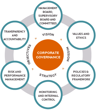
An example of corporate governance framework issues to address.
Image credit: Wikimedia/Creative Commons
ESG policies should include very clear and specific objectives and targets. This will ensure that the policies are implemented accurately and effectively. These objectives and targets should also be quantifiable and aligned with a company or organization's larger mission, vision statement, and business plan. For example, if a company is planning to reduce its greenhouse gas emissions by 35% by the year 2030, they must explain how they will do that, how they will measure it, and be able to prove that they are meeting the goal. The policies should be developed with input and participation by employees, stakeholders, and shareholders, and must be transparent and attainable in order to be effective. Polices will need to be reviewed and modified as situations, values, and circumstances change and as new tools, technologies, and opportunities arise.
Reporting of ESG measures and plans requires analyzing specific forms of data in order to create an ESG rating or ESG score. This information is used by investment analysts to determine their effectiveness and accuracy, which will then in turn determine whether or not a business or company can become engaged with a proposed business, project, or investment. Carbon accounting software is a significant part of reporting, since carbon emissions reduction and/or carbon neutrality are important aspects of the environmental issue of ESG. For example, to create a complete and accurate picture of the emissions, it is important that the report includes the source and measurements of current impacts, specific activities or measures to reduce or offset carbon emissions, and how this is certified.
There are a number of ESG reporting frameworks due to the variety of companies that are participating in this type of reporting. There are also such a wide range of industries that have different types of ESG impacts and aspects, so the reporting frameworks need to be able to report on different types of metrics. Additionally, different types of stakeholders such as investors, regulators, and even consumers often want to be able to review various types of information. Each of the ESG reporting frameworks will have their own type of metrics, methodology, and scoring system. This can make it difficult to compare information. So, it is important to have a good understanding of how the information is collected, analyzed, and presented in order to interpret it correctly. The most popular ESG reporting frameworks include standards developed by the Carbon Disclosure Project, Climate Disclosure Standards Board, Global Reporting Initiative, International Integrated Reporting Council , and the Sustainability Accounting Standards Board.
Today, businesses and organizations that have robust ESG policies tend to gain consumers and investors that also value sustainability and ethical behavior and decision-making practices. When ESG issues are prioritized, it is also possible to reduce risks and cultivate better relationships with investors, employees, and other organizations, businesses, and companies that are in alignment with these values. Additionally, investors now prefer, and in many cases are required, to support only socially and environmentally responsible businesses, companies, and organizations. With the increased focus on addressing climate change, more businesses, companies, and organizations will need to be a part of the solution, especially since any business activity, product, or project that is carbon intensive is now considered high risk.
ESG policies show a commitment to doing more than just generating a profit and to demonstrating values that have a positive impact on people and the planet. ESG policies also help reduce operating costs and increase employee engagement and satisfaction. They can also improve the financial standing and performance as well as the reputation of a business or company over the long-term.

Solar energy and wind power are among the many forms of renewable energy sources that can be implemented to meet ESG goals such as reducing carbon emissions. Photo Credits, Left to Right: NREL.gov and DOE.gov.
ESG can also align with and support larger initiatives such as the U.N.'s Sustainable Development goals, LEED, Living Future Challenge, and other green-rated building projects, Zero Net Carbon Buildings, the Fair Housing Act, and many other strategies, investments, and markets that are engaged in creating a more sustainable, resilient, inclusive, and just future for all.
For example, if a building is designed to meet LEED or other green building rating system requirements, ensuring that it performs as intended, can directly tie to the organizations and companies who own or lease the building or spaces through the ESG policies. In another case, for a residential real estate investor it may be detrimental to the approval and funding of a housing project if it is not meeting LEED requirements, addressing fair housing laws, or located near good schools. It is important to also consider ESG before acquiring an existing building to better understand and plan for the eventual transition that may entail upgrades, retrofits, and other strategies that are necessary to bring the property into alignment with ESG.

ESG through the lens of the U.N.'s Sustainable Development Goals Image Credit: United Nations
As ESG continues to grow and become more ingrained into business, investing, and the economy, there will be a need to look at the issues more holistically. This means that all of the potential impacts that a company or organization has on the world around them will need to be considered and addressed. This will also entail creating a culture within the business or organization that is committed to the ESG goals and where everyone feels a sense of responsibility to the objectives. This may also require hiring and collaborating with new people that align with the mission and vision of the company or organization and the ESG goals.
Technology advancements and improved access to ESG-related data will only continue to further enhance the ability of investors to assess a business or company's ESG performance more accurately. As a result, development of more sophisticated ESG investment products and strategies, as well as an increasing integration of ESG goals into mainstream investment decision-making, are likely to happen in the near future.
Mechanical insulation systems are defined as the materials and components used to insulate piping, equipment, vessels, ducts, and other types of mechanical items. Although important to facility operations and manufacturing processes, mechanical separation is often overlooked and undervalued. National standards, universal energy policies, or generally accepted recommendations as to what should be insulated, what insulation systems are acceptable for a specific use, and application best practices do not currently exist. As a result, the value of mechanical insulation is not being realized to its potential for energy conservation, reducing the dependency on foreign energy sources, improving the environment by reducing greenhouse gas emissions, improving global competitiveness, and providing a safer work environment for personnel and process.
Insulation is applied, but it is rarely engineered. With the best intentions, but not necessarily thorough knowledge, many specifications have evolved over the years primarily based on the modification of old documents. This practice-combined with the lack of education and awareness programs on the value of having a properly engineered, installed, and maintained mechanical insulation system-has led to the underutilization of mechanical insulation in energy conservation, emission reduction, process and productivity improvement, life-cycle cost reduction, personnel and life safety, workplace improvements, and a host of other applications.
Whether someone is looking for basic insulation information or needs to design a complex insulation system, NIA's Mechanical Insulation Design Guide (Design Guide) is the best resource. Designed to assist the novice or the knowledgeable user alike in the design, selection, specification, installation, and maintenance of mechanical insulation, the Design Guide is continually updated with the most current and complete information.
Click to visit the Design Guide
Mechanical insulation is often used to limit heat gain or loss from operating at temperatures. However, there are far more reasons to use insulation on a project and that reason will impact the final insulation system design. Of course, insulating may be done to achieve multiple goals. Here are some common reasons.
Condensation Control: minimizing condensation and the potential for mold growth by keeping the surface temperature above the dew point of the surrounding air. This can also help avoid slip and fall hazards.
Energy Conservation—Financial Considerations: minimizing unwanted heat loss/gain from systems while minimizing the use of scarce natural resources and saving operational expenses.
Economic Considerations—Return on Investment: maximizing return on investment and minimizing the life-cycle cost.
Economic Thickness Considerations: considering the initial installed cost of the insulation system plus the ongoing value of energy savings over the expected service lifetime.
Environmental Considerations—Sustainability: minimizing the emissions associated with energy usage of projects.
Fire Safety: protecting critical building elements and slowing the spread of fire in buildings.
Freeze Prevention: minimizing energy required for heat tracing systems and/or extending the time to freezing in the event of system failure.
Personnel Protection—Safety: controlling surface temperatures to avoid contact burns (hot or cold).
Process Control: minimizing temperature change in processes where close control is needed.
Noise Control: reducing/controlling noise in mechanical systems.
In some projects, multiple design objectives must be satisfied simultaneously. For example, the objective may be to provide the economic thickness of insulation and to avoid surface condensation on a chilled water line. The chilled water line may pass through various spaces within the project. Since the various spaces may have differing temperature and humidity conditions, it is likely that different insulation materials, thicknesses, and coverings may be required for a single line. Because projects may involve many lines, operating at different service temperatures in various environmental conditions, it is clear that a systematic approach is required for all but the simplest projects.
Learn more about these design considerations and how to plan a project, or use the insulation design calculators at the Design Guide website.
The design process for mechanical insulation systems entails developing answers to six basic questions: Why? What? Where? How? How to? and How much?
The Design Guide is divided into sections that answer each of these questions:
The Design Guide was created by the National Insulation Association to address these questions and includes information on the design, specification, installation, and maintenance of insulation systems used in the commercial and industrial sectors.
The overall objective of the Design Guide is to identify, develop, and disseminate information related to mechanical insulation in commercial and industrial applications by examining current policies, procedures, and practices; identifying research or testing needs; developing recommendations utilizing the best science and information available; providing education and awareness programs as to the merits and value of properly designed, installed, and maintained insulation systems; and to establish a roadmap to implement improvements in insulation system design and selection; and establish application best practices. It is continually updated as deemed necessary and appropriate by the NIA to reflect current and state-of-the-art information.
Mechanical insulation encompasses all thermal, acoustical, and personnel safety requirements in:

Removeable blanket insulation Image credit: Christopher Vella/Wikimedia Commons
Mechanical insulation in the Commercial Sector is defined to include systems used in education, health care, institutional, retail and wholesale, office, food processing, light manufacturing, and similar types of applications.
Mechanical insulation in the Industrial Sector is defined to include systems used in power, petrochemical, chemical, pulp and paper, refining, gas processing, brewery, heavy manufacturing, and similar types of applications.
The scope of the Design Guide includes the design, specification, installation, and maintenance of insulation systems for use within the markets defined above. Specialized insulated air-handling products (flex-duct, duct liner, and duct board products) are not considered to be mechanical insulation in the context of this Design Guide and are not addressed.
The Design Guide is an evolving, online resource intended to provide architects, engineers, facility managers, project managers, etc. with design guidance, criteria, and technology for mechanical insulation systems. The Guide is continually updated with new information and is structured as a "vertical portal," enabling users to access increasingly specific information as they navigate deeper into the site.
Click here to access the Mechanical Insulation Design Guide.
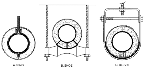
Insulating Pipe Hangers Image Credit: ©American Society of Heating, Refrigerating and Air-Conditioning Engineers, Inc.
Research and Data
Insulation Industry Opportunity Study
A coalition of trade associations, including the North American Insulation Manufacturers Association, the Insulation Contractors Association of America, the National Insulation Association, the American Chemistry Council (Plastics Division), and the Polyisocyanurate Insulation Manufacturers Association, commissioned a study that quantifies the benefits of completing insulation retrofit projects across residential, commercial, and industrial buildings and underlines the potential impact forward-thinking policies can have on decarbonizing the built environment. A press release, Executive Summary , full copy of the study , and webinar are available for reference.
A Study on Insulation's Positive Impact on Energy Efficiency and Emission Reductions
The National Insulation Association (NIA) and the Foundation for Mechanical Insulation Education, Training, and Industry Advancement commissioned—for the first time in the history of the mechanical insulation industry—a study to determine the impact mechanical insulation systems can have on reducing the demand for energy and greenhouse gas emissions. This analysis of high-service temperature ranges (150°F–800°F) examines and interprets an 11–year window of information.
For more information about this study please visit insulation.org/about-insulation/carbon-reductions/
It can be difficult to find information on mechanical insulation, so NIA members and staff have created and compiled the following free technical resources. NIA's Technical Information Committee (TIC) reviews and updates these documents quarterly.
To access NIA's codes and specification resources including the Insulation Materials Specification Chart and Guide to Insulation Product Specifications click here.
The following are examples of commonly referenced government codes and standards:
NIA has a vast collection of technical resources about mechanical insulation and the general insulation industry.
Glossary of Mechanical Insulation Terms: This extensive glossary can help make sense of even the most technical insulation jargon. Click here to access the glossary.
Insulation Outlook Magazine: An award-winning publication, Insulation Outlook® is the only international magazine devoted exclusively to industrial and commercial insulation applications, products, and materials. It is free for engineers, specifiers, mechanical contractors, and insulation end users. For subscription information, click here. To access Insulation Outlook's article database, click here.
Insulation Products and Providers: For the most up-to-date information on how to use or install insulation products or accessories, it is best to reach out directly to the experts. For contact information on NIA member companies, click here.
MICA's National Commercial & Industrial Insulation Standards Manual: The National Commercial & Industrial Insulation Standards Manual was developed by the Midwest Insulation Contractors Association (MICA) to serve as a useful resource for commercial and industrial insulation professionals. Widely accepted as the industry standard, the manual is a must-have guide for contractors, engineers, architects, and specifiers. For more information about the MICA National Commercial & Industrial Insulation Standards Manual, click here.
NIA's Online Store: NIA is committed to delivering access to top products and services that provide technical resources, increase industry awareness, and improve worker safety. If a specific product cannot be found, please contact products@insulation.org. To access NIA's online store, click here.
NIA is committed to industry advancement and offers access to a variety of training opportunities and online tools for NIA members and non-members. The resources listed below are designed to advance a business and increase industry and technical knowledge.
NIA's Education Center: NIA's Education Center is a new concept in training and education for the insulation industry to meet the growing need for easily accessible, on-demand training from a trusted industry source. With more than 30 topics in development, it will be the go-to national resource for information and training tools specifically designed for anyone who is involved in the mechanical insulation industry.
Free Industry Resources—Available to everyone through the Education Center.
For information about the NIA Education Center email training@insulation.org. To explore the NIA Education Center, click here.

NIA's Thermal Insulation Inspector Certification: NIA's Thermal Insulation Inspector Certification Program, a two-part, four-day course to educate insulation inspectors on how to evaluate installation work and determine whether it is compliant with mechanical insulation specifications.
NIA Certified Thermal Insulation Inspector Benefits
This certification program provides education on mechanical insulation, how to verify that the insulation is being installed to the specification, and how to identify potential areas of concern during initial installation or ongoing operations. This certification-level course is designed for experienced insulation professionals ready to learn a new specialty and companies ready to offer insulation system inspection as part of their services. The course is beneficial for anyone who has responsibility for contracts, maintenance, business development, quality assurance (QA)/quality control (QC), project oversight, safety, inspections, estimating, management, product development, mechanical insulation system design, and specification development. For more information about NIA's Thermal Insulation Inspector Certification program, click here. To find a Certified Thermal Insulation Inspector, click here. For a list of insulation inspector program FAQs, click here.

NIA's Insulation Energy Appraiser Certification: The Insulation Energy Appraisal Program™ (IEAP) is a 2–day course that teaches students how to determine the optimal insulation thickness and corresponding energy and dollar savings for a project. The program was designed to teach students the necessary information to give facility managers a better understanding of the true dollar and performance value of their insulated systems.
During the course students will learn how to conduct a facility walkthrough; use the 3E Plus® software; utilize infrared cameras during inspections; understand steam efficiencies; analyze and complete an appraisal spreadsheet; and present a customer with a final report that outlines the potential savings and emission reductions that mechanical insulation can provide. If interested in taking the IEAP course, email training@insulation.org for more information.
Certified Appraisers: Students who pass the certified course exam become Certified Insulation Energy Appraisers™. The certification is valid for 3 years, after which the individual must recertify. After passing the exam, students will receive a certificate, lapel pin, and marketing kit. The marketing kit includes the official copyrighted Certified Insulation Energy Appraiser™ logo to promote their certification to clients. For more information about NIA's Insulation Energy Appraiser Program, click here. To find a Certified Thermal Insulation Inspector, click here.
The purpose of the ACP is to define designs standards for buildings, site development, and streetscapes that serve to integrate the visual character throughout the base.
This Installation Facilities Standards (IFS) document is part of the Air Force Corporate Facilities Standards (AFCFS) program and provides facility design standards for Pease Air National Guard Base. IFS replaces the Architectural Compatibility Plan (and similar legacy documents), as a component plan of the Installation Development Plan (IDP). For more information contact the Base Civil Engineer.
This ANGETL provides streamline procedures for processing new and annual renewals of waiver requests for deviations from airfield and airspace criteria and standards on land that is under the Air National Guard jurisdiction. It supplements the requirements outlined in United Facilities Criteria (UFC) 3-260-1.
This ANGETL defines what an ANG MCCA is, when it is appropriate to use an MCCA, and what the procedures are to enter into an MCCA. The National Guard Bureau’s Office of Grants and Cooperative Agreements (NGB-PARC-A) is responsible for the oversight and management of the National Guard Grants and Agreement Program. The purpose of this ANGETL is not to replicate the policy guidance for this program that is managed by NGB-PARC-A, but to outline the steps necessary to enter into an MCCA and the procedures to follow when an MCCA is necessary to support an ANG Military Construction Project (MCP), a Sustainment, Repair, or Maintenance (SRM) Project, or other construction project.
This ANGETL provides guidance for compliance with Handicapped Accessibility Laws and Standards on ANG Installations. This ETL supersedes ANGETL 98-02 Compliance with Handicapped Accessibility Standards.
This ANGETL and its two companion ANGETLs provide guidance to the BCE on the design process and construction as it pertains to the relationship between the BCE and NGB/A7O and not the onsite day to day construction management. The companions are ANGETL 12-06 Design Meetings and Presentations and ANGETL 12-07 Preparation of Project Documentation Package.
This ANGETL is a companion to ANGETL 12-05, Design and Construction Handbook. This ANGETL provides guidance to the Base Civil Engineer (BCE) for preparing documentation for Military Construction (MILCON) and Sustainment Restoration and Modernization (SRM) projects at the beginning of the design process. This documentation is provided to the A-E at the beginning of the design process. It applies to projects utilizing an Architech Engineer (A-E) in the design, bid, and build environment for NGB and locally approved projects.
*This ANGETL should be read in conjunction with the ANGETL 12-05, Design and Construction Handbook.
The purpose of this ANGETL is to outline and explain the Element of Expense Investment Codes (EEIC's) authorized for use in implementing civil engineering agreements developed in support of Facility Operations (FO) formally known as Real Property Services (RPS) and Sustainment, Restoration and Modernization (SRM) funds as part of the Master Cooperative Agreement (MCA) with each state. The Master Cooperative Agreement Appendices covered by this ANGETL are Appendix 21, ANG Facilities Operations and Maintenance Activities (FOMA); Appendix 22, ANG Environmental; Appendix 24, ANG Fire Protection. This ANGETL also provides submittal instructions for Financial Plans (FinPlan) prepared in support of these appendices.
Provide general policy guidance on the proper funding sources for acquisition of, as well as operation and maintenance costs in support of facility alarm systems or components, permanently installed bollards, drop-arm barriers, tire shredders, pop-up barriers, and Aircraft Arresting Systems.
This ANGETL prescribes the policies and procedures for administering certain sections of the Master Cooperative Agreement (MCA) for janitorial services through contractual service or with in-house maintenance personnel.
This ANGETL prescribes the policies and procedures for calculating work order shop rates of the in-house ANG CE maintenance staff.
This ANGETL provides design policies for the Air National Guard.
The purpose of the ANGETL is to inform and implement increasingly robust sustainability thresholds for best practices in sustainable planning, design and construction of sites and facilities as well as to comply with energy and water resource conservation federal directives.
The purpose of this ANGETL is to provide guidance in implementing the mechanical and plumbing design policy.
This ANGETL is to provides guidance in implementing the electrical design policy.
This ANGETL implements required project closeout procedures necessary for the physical and financial closeout of MILCON constructions projects.
This ANGETL provides reporting requirements associated with the design and construction of Air National Guard (ANG) Military Construction (MILCON) and Sustainment, Restoration, and Modernization (SRM) projects.
This ANGETL is a companion to ANGETL 12-05 Design and Construction Handbook. This ANGETL provides guidance for the Military Construction Program (MCP) and selected Sustainment, Repair and Modernization (SRM) projects on conducting the following meetings and presentations:
*This ANGETL should be read in conjunction with the Design and Construction Handbook.
To provide guidance in implementing ANGI 32-1003, Facilities Board.
This ANG ETL provides guidance to the Air National Guard (ANG) Civil Engineering community and contracted consultants defining required format for GIS data created for and delivered to the ANG.
*NOTE: This ANG ETL supersedes ANG ETL 17-11, Geographic Information Systems (GIS) Data Format Specifications which supersedes ANG ETL 32-1018, Project Execution Process for Electronic Data Deliverables.
This ANG ETL provides guidance to the Air National Guard (ANG) Civil Engineering for Sustainment Management System Guidance to meet the Office of Secretary of Defense requirements.
This ANGETL documents a Financial Improvement and Audit Readiness (FIAR) compliant process to be used to track ANG CIP and capital improvements (CIMP) to existing assets. It outlines the ANG process to account for the costs associated with all ANG construction type projects (major & minor construction) and work items whose full, or partial, value is determined to be capitalized and/or expensed by the base Real Property Officer/Base Civil Engineer.
This ANGETL provides programming requirements for the Air National Guard.
This ANGETL prescribes the policies and procedures for calculating work order shop rates of the in-house ANG CE maintenance staff.
This ANGETL provides guidance in implementing the Sensitive Compartmented Information Facility (SCIF) and antiterrorism (AT) design policy.
This ANGETL provides guidance in implementing the Air National Guard (ANG) fire protection design policy.
This ANGETL provides guidance in implementing the electrical design policy.
To provide design policy for ANG airfield and vehicle pavements.
The Air National Guard (ANG) Design Objectives and Procedures, developed by the National Guard Bureau (NGB)/A4I, is established to define the overall objectives in accomplishing the ANG facilities design and construction management program and the procedures to be followed in achieving that end.
This Air National Guard Instruction (ANGI) implements the Training Site program which provides Civil Engineers and Force Support Squadrons (FSS) the opportunity to accomplish contingency and AFS skill level hands-on training requirements that cannot be obtained through home station training due to complexity of tasks, uniqueness of equipment, and cost of Air Force-wide implementation to maintain the highest state of readiness possible. This publication redefines the Regional Training Sites purposes. It adds the RED HORSE Training Center to the venues and aligns the available training with the requirements in AFIs 10-209 and 10-210. It also redefines roles and responsibilities.
This instruction provides direction to the Air National Guard Installations and Mission Support (NGB/A7), State Military Departments, Base Civil Engineers (BCE), and design and construction agents concerned with the facility maintenance and construction of ANG facilities. Policies, procedures and criteria outlined in this instruction apply to all ANG facility operations and maintenance and minor construction projects, whether entirely or partially federally funded.
This instruction outlines procedures for Unit enhancement, training and implementation of Affiliated Units with Staff Augmentation Teams (S-Teams). This instruction recognizes that the demand for theater engineering assets is high and capitalizes on the opportunity for S-Team and Affiliate Units to train together and be a viable resource to the ANG and the Air Force. By establishing informal relationships at home stations and in training environments, team integrity will be enhanced when deployed together in theater. The S-Team units and Affiliate Units will work together to foster a spirit of cooperation and collaboration to enhance training and increase capabilities. Affiliate Units are still under ADCON and OPCON of their various states, but will train to the same Air Force Instruction 10-210 standards as S-Teams, since they may be mobilized and deployed in support of S-Team missions. This relationship is strictly informal during non mobilization periods but highly encouraged since they will be mobilized into a single unit.
This instruction implements AFPD 32-10, Installations and Facilities. It establishes the Facilities Board (FB) at each Air National Guard (ANG) installation and assigns responsibilities and membership.
This document is substantially revised and must be completely reviewed.
This ANGI provides direction to the Air National Guard Installations and Mission Support Directorate (NGB/A7), United States Property and Fiscal Officers (USPFO), State Military Departments, Base Civil Engineers (BCEs), and design and construction agents concerned with the design and construction of ANG facilities.
This pamphlet implements AFPD 10-10, Civil Aircraft Use of United States Air Force Airfields, and AFPD 32-10, Installations and Facilities, and applies to Air National Guard (ANG) flying units that operate on public airports. This pamphlet provides guidance for negotiating fair and reasonable charges to the Government (AF) for joint use of the flying facilities of a public airport.
This document is substantially revised and must be completely reviewed.
This publication is dedicated to providing the basic information needed to support your program. This pamphlet is written as a procedural guide and not intended as an instruction or as a mandatory procedure. It is a guide only to be used by ANG Civil Engineers for local self-help programs. It is not all-inclusive and some of the suggestions and checklists may or may not apply to your self-help program. As with any program it requires the support of all functional managers within civil engineering and the base populace.
Animal research and animal research facilities are critical to the biomedical research enterprise. Animal species are used in every stage of the research and development effort-from discovery, to development and safety testing, to clinical trials, and to manufacture-because their biological systems, genetic structures, and immunological responses, in various ways, closely mirror ours as a species.
Numerous organizations have clearly articulated the importance and the value of animal research. Three of them are:
The animal research facility, also known as the vivarium, is a specially designed building type, which accommodates exquisitely controlled environments for the care and maintenance of experimental animals. Animal research facilities are related to but distinct from research laboratories. The facilities are complex, and expensive to build and to operate, but they are vital to the support of a proper, safe, and humane research effort.
Clients are pushing project design teams to create laboratories that are responsive to current and future needs; that encourage interaction among scientists from various disciplines; that help recruit and retain qualified scientists; and that facilitates partnerships and development. As such, a separate WBDG Resource Page on Trends in Lab Design has been developed to elaborate on this emerging model of laboratory design.
Whether vivariums are embedded within a lab building, are in a separate structure connected to a lab building, or are independent free-standing structures, they share the same basic attributes.

Walter Reed Army Institute of Research, Forest Glen, MD—A technically advanced, highly flexible facility which houses multiple organizations from the Army & Navy's major domestic biomedical research activities. Photo Credit: HLW International LLP
Through the capabilities of their particular architecture and building systems, they maintain tight environmental control over the facility to avoid the introduction of contaminants or pathogens, and prevent the possibility of infectious outbreaks, and avoid the transmission of odors. See also WBDG High-Performance HVAC.
These facilities are fundamentally about the care and maintenance of the experimental animals.
Promote maintainability and cleanliness. See also WBDG Sustainable O&M Practices.
Organize circulation to permit controlled flows of people, animals, material, supplies, and wastes.
The ability of the operator to maintain and adapt environmental control within spaces and between circulation paths and to avoid contaminants or infection.
Cage sizing and cage systems are species-dependent and are governed by the standards set forth in the Guide for the Care and Use of Laboratory Animals. These in turn influence room sizes, room environment, and circulation patterns.
Research using animals is sensitive, and the design of these facilities requires a heightened awareness to the issues of security control to maintain confidentiality and to prevent unauthorized intrusions.
Animal Housing Rooms (AHRs)—Accommodate caging, bedding change stations, and sinks. See Figures 1, 2, and 3 for examples. AHRs can be organized as individual rooms accessed from a corridor system or multiple rooms could be organized into self-contained suites.
Figure 1: Animal Housing Room for Rodents in Ventilated Racks View enlarged plan
Figure 2: Animal Housing Room for Non-human Primates View enlarged plan
Figure 3: Animal Housing Room for Dogs View enlarged plan
Procedure Rooms—Proximate to AHRs and frequently interchangeable with them; they are a primary setting for research activity within the unit. The method of allowing researcher access under controlled conditions is a critical issue to be solved.
Barrier Elements—Airlocks, lockers, pass-through autoclaves. These provide the primary barrier and access control that separates the controlled animal care environment from external influences.
Cagewash—The hub for all cleaning, sanitizing, and husbandry activities. These areas are dominated by equipment-generated heat and moisture. The major equipment items include pass-through rackwashers, tunnelwashers, pass-through autoclaves, bedding dispensers and dump stations, and bottle washing and filling stations.
Cage Storage—A necessary function, but a space consumer, which unfortunately is frequently short shrifted.
Storage—A necessary space and function for feed, bedding, and equipment has to be incorporated into the operational flow and space allocation.
Quarantine—Isolated AHRs for suspect and incoming animals that could be a source of infection.
Dedicated Receiving Dock—A dock specific to animal functions is generally required. An elevator dedicated to animal usage should be located near the dock.
Necropsy/Perfusion—Critical support function used for post mortem procedures on sacrificed animals. A "dirty" function that should not be proximate to "clean" areas.
Containment Facilities—Facilities for working with potentially infectious biological agents. They operate under negative pressure to prevent the escape of air to the general environment. Wastes and effluents are separately contained and decontaminated. Sophisticated control and monitoring systems and equipment are employed to achieve closely controlled and regulated air pressurizations and flows.
Barrier Facilities—Facilities for working with immuno-compromised species. These operate under positive pressure to keep contaminants out. As in containment facilities, control and monitoring systems and equipment are utilized in barrier facilities to maintain the required pressures and flows.
Veterinary Care—Lab and care functions, e.g. surgery, clinical chemistry, and histology.
Veterinary Office Space—Some provision for in-unit office spaces for veterinary care staff.
Staff Support Areas—Break area, cafeterias, workstation, lockers, and rest-room facilities. All are intended to support veterinary and research staff during their in-unit tours of duty.
Mechanical/Electrical Equipment Spaces—Mechanical equipment rooms, electrical and telecom closets, rooms for terminal trim devices such as dampers, coils, humidifiers and controls, distribution shafts, and mechanical penthouses. A desirable goal is to locate the spaces and devices in a manner that allows the separation of maintenance functions from animal care functions.
Corridors tie everything together. These should be wide enough to accommodate animal rack, cart, and material traffic flow, not just egress requirements. Corridors should have a clear width of 7'–0" to 8'–0". Corridors should have impervious finishes so that they are easy to clean and maintain. Protective components such as bumper and corner guards are frequently employed to protect walls and doors from heavy, abusive traffic.
The general organization of a vivarium is illustrated in Figure 4.
Important Attributes
Floor-to-Floor Height—The clear height from floor to ceiling should be 8'–6" to 9'–0". The clear height above the ceiling should be 5'–0" to the underside of the structure to accommodate infrastructure support system distribution. Overall floor-to-floor height should be approximately 16'–0".
Floor and Framing System—Should be stable, monolithic, (preferably concrete), and capable of a 125 psf live load to dampen vibration. Epoxy terrazzo or resinous floor coatings are preferred.
Interior Walls and Partitions—Should be stable and capable of withstanding abuse and wash-down. Concrete masonry units are preferred substrate because of their strength and stability. There are many combinations of wall coatings, most of which employ block filler on CMUs for a smooth surface, trowelled on or sprayed on cement or epoxy based undercoatings, and are top coats with epoxy based products. Steel studs and moisture-resistant gypsum board can be used if necessary but should be coupled with protection, e.g., rails, bumpers, corner guards. Walls should have an impervious, easily cleanable finish, either block filler with latex paint, high-build coatings, or solid panels.
Doors—Should be a minimum of 42" wide and 84" high or more. Doors should be tall enough to accommodate the free movement of racks with integrated blowers. The opening size depends on the cage and rack system in use. The other key principle is that door assemblies should be constructed to prohibit the growth of vermin or bacteria. There are numerous system choices. What they should have in common is solidity, that is the absence of voids in the top and bottom rails of the door, the jambs and the strike; an easily cleanable and maintainable surface like epoxy painted steel, stainless steel, or fiberglass reinforced plastic (FRP); and surface that won't dent or dink. Doors need to be properly protected, particularly latches, locks, and other hardware. Continuous hinges are preferred.
Ceilings—Should consist of moisture-resistant gypsum board, latex paint or high-build coating, and sealant at intersections with walls and openings to ensure air and water tightness.
Overall system design is largely governed by the Guide for the Care and Use of Laboratory Animals and ASHRAE Handbook—HVAC Applications, Chapters 16 and 24.
Example Building Automation System (BAS) that controls airflow and space temperature, and monitors system performance, etc. from a central location.
It is the maintainer of environmental control via regulation of airflow, air cleanliness via filtration, temperature, humidity, odor transmission, and contaminant control.
Air changes per hour, a key benchmark of system capability, can vary from a minimum of 10 to greater than 20, which equates to 1.5 cfm/sf to more than 3 cfm/sf.
Air quality, caging type and caging density are the primary determinants of airflow rate.
Since HVAC is the life-sustaining system, consideration should be given to methods of providing redundancy and backup to maintain continual operation. See also WBDG Productive—Assure Reliable Systems and Spaces.
Plumbing systems are pervasive, but are varied, discrete, and independent. The most important elements are animal watering and major water users such as cage and rack washers. Watering system vendors maintain reliable empirical databases on watering needs by species. For major equipment, load capacity is calculated system by system.
Electrical systems are ubiquitous. The most critical issues are reliable power and redundancy and back-up for critical systems and equipment via standby generators, weather-protected outlets in wet locations, and the increasing use of computers in procedure and holding rooms. Other critical electrical systems include: lighting cycle control, security, and monitoring of water usage.
In the New York City metropolitan area, new animal research facility construction in 2005 costs $425 — $475/sf, renovations cost $325 — $375/sf. Nationwide costs are generally 85% — 95% of the NY metro costs, depending on local market conditions.
MEP systems represent 45% — 50% of the total construction cost.
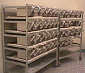
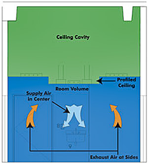
Automated record-keeping and integration with Building Automation Systems.
Initiatives to promote psychological well-being of animals are affecting all species. Providing for such natural behaviors as exercise, opportunities for group interactions, and nesting and foraging are warranting new ideas to replace more stressful traditional housing paradigms.
Labor saving technologies such as robotics and to a lesser extent, overhead gantry- or floor rail-based-systems, are being more extensively applied in cagewash facilities.
Reliance on the institutional knowledge of veterinary staff at all levels during the design process is increasing.
A "zoning" approach to facility layout that allows access to daylight via windows or other means at office and non-sensitive support spaces without having the staff leave the animal environment. This approach also provides for maintenance and device access zones for non-vivarium operational staff to service the vivarium MEP systems without crossing the animal environment barrier.
Designing the AHR space as a flexibly-rearranged entity which can be readily changed between animal holding and procedural functions with a minimum of refit as study paradigms change.
NAVFAC Planning, Design, and Construction Criteria provides antiterrorism and security engineering criteria training to NAVFAC components in support of the Chief Engineer's community management plan.
Julie Heup, P.E.
Special Assistant for Antiterrorism and Security Engineering
Planning, Design, and Construction Criteria
Naval Facilities Engineering Systems Command
Norfolk, Virginia
John Lynch, P.E.
Antiterrorism and Security Engineering
Planning, Design, and Construction Criteria
Naval Facilities Engineering Systems Command
Norfolk, Virginia
Synopsis
Sessions
NAVFAC FAR EAST 2024
Synopsis
Sessions
NAVFAC FAR EAST 2024
Synopsis
Sessions
NAVFAC FAR EAST 2024
Synopsis
Sessions
NAVFAC FAR EAST 2024
Synopsis
Sessions
FAR EAST 2024
Synopsis
Sessions
NAVFAC WASHINGTON 2024
Synopsis
Sessions
NAVFAC FAR EAST 2024
Synopsis
Sessions
NAVFAC FAR EAST 2024
Synopsis
Sessions
NAVFAC FAR EAST 2024
Synopsis
Sessions
NAVFAC FAR EAST 2024
Work on historic buildings, landscapes, archaeological sites, or other cultural resources, requires knowledge of a unique process of compliance and review. This process differs from work on existing buildings or on new construction. The preservation process involves five basic steps: Identify, Investigate, Develop, Execute, and Educate. They should be considered in concert with other project goals requiring close collaboration between preservationists and design disciplines. To ensure a balanced, economically viable, and preservation-sensitive project, the outline below should be followed. Work on existing buildings or on new construction should also be considered in concert with other project goals requiring close collaboration between preservationists and other design disciplines.
Properties may be designated as historic at the federal, state, and/or local government levels. Designation recognizes a property's historic, architectural, and community value, and from a sustainability perspective, is an indication that a building is worthy of preservation. All designating agencies use qualifications that emphasize age (usually 50 years old and older), historic significance, architectural and engineering merit, and integrity of design, character, workmanship and materials. Integrity means how well a building or property has retained the important aspects of its historic construction, appearance and association.

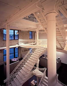
Minneapolis Brewing Company, Brew House; Minneapolis, Minnesota. This imposing building was constructed in 1891 in NE Minneapolis for the production of "Grain Belt Beer." Abandoned for several decades, the project earned an award, for its rehabilitation into office space, by the National Trust for Historic Preservation. Photo Credits: National Park Service and AIArchitect
Written and photographic documentation of a property, including a narrative description and a statement of significance, is required for nomination. This documentation, presented in the National Register of Historic Places Registration Form (NPS Form 10-900) or a state or local inventory form, is a key source of information to use in planning for treatment of a building. An on-line index of National Register properties is available at here.
Some income producing properties listed in the National Register, or eligible for listing in the National Register, may qualify for a federal historic preservation tax credit. States may also offer state tax credits to eligible properties.

Monticello, Charlottesville, Virginia, Thomas Jefferson, 1768 to 1782. Photo Credit: Library of Congress, Prints & Photographs Division, FSA-OWI Collection, John Collier Photographer. Reproduction number, e.g., LC-USF35-1326
National Register designation offers some protection when federal actions may impact a property. Federal financial assistance, permit, or license trigger a consultative review process known as Section 106 review which aims to avoid, minimize, or mitigate adverse effects on historic properties. The protections apply when properties are eligible, even if they are not officially listed in the National Register. Private actions are not regulated regarding National Register listed properties, although local zoning may impose local review requirements if changes are proposed for a historic building. Some states also have state laws that protect historic properties.
State Historic Preservation Offices (SHPOs) are sources of information on designated federal and state historic buildings, tax credits, and relevant laws and regulations. See ncshpo.org for a list of SHPO contacts.
Community engagement is important. Interested parties and the public can contribute insights, information and talent to the success of a project. So consider working with advocacy groups, neighborhoods, and local community organizations in the process. Likewise, professionals with related skills in architectural history, historic architectural design, ethnography, and community planning can recognize and help accommodate historic significance, architectural character, and intangible value in the final project. Build a team that best fits the needs and goals of the project.
Completing a state and/or national historic register nomination requires general knowledge of the resource type being considered (building, landscape, archaeological site), which necessitates investigation and historical research requiring qualified preservation professionals. Procuring qualified preservation professionals can make the process more efficient. (Refer to section on Form a Qualified and Experienced Project Team in Section B below.) There may also be regulations, guidelines, and applicable codes that must be followed. Preparing a nomination should be done in consultation with the consulting agencies (State Historic Preservation Officer, the Federal Preservation Officer, and the Tribal Historic Preservation Officer) to make certain all requirements are met.
For the long-term preservation of a historic property, it is very important to understand its history before any construction begins. Consider the following:
Archival research to verify the original appearance of the building and site is helpful in establishing preservation priorities and in preparing treatment alternatives.
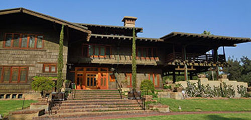
The Gamble House in Pasadena, California, designed by Greene and Greene in 1909 is considered to be one of the finest examples of Craftsman architecture in the U.S. A major restoration of the house was undertaken between 2003 and 2004. Photo Credit: National Park Service
An excellent planning tool for successfully completing a project for any historic resource is to develop a Preservation Management Plan. This plan may address a single building or multiple facilities and cultural resources. This document records a resource's history, why it is significant, what are the most important features to preserve. The plan delineates which areas require special protection or which areas first merit rehabilitation. The preservation management plan guides future maintenance, repairs, and alterations. Some also provide detailed guidance for rehabilitation or adaptive use.
The following are sources to aid in archival research concerning the property:
When a treatment is proposed for a historic property, compliance involving a variety of public agencies may be required. Compliance with multiple federal laws is mandatory if the property is using federal funds, leases, grants, permits, or licenses (even if the historic resource is privately owned), is on federal land, or is under the jurisdiction of the federal government. For example, the National Environmental Policy Act (NEPA) requires project planners to assess the environmental effects of their proposed action before major renovations proceed. To save time and money, determine ahead of time who must review the preservation project and learn what is required for approval (at all governmental levels).
Section 106 and Section 110 of the National Historic Preservation Act (54 U.S.C. § 300101 et seq.)
Section 106, 36 CFR Part 800, Protection of Historic Properties: Section 106 regulations require that the head of any federal agency "prior to the approval of the expenditure of any federal funds on the [construction] undertaking... take into account the effect of the undertaking on any [historic] district, site, building, structure, or object". Or, more simply, if federal funds are used to do work on an individual property, then studies must be conducted to determine the potential effect of the work on the property. If any historic or cultural resource (building, land, structure, object, or feature) will be adversely affected by the work, then mitigation and/or remedial plans must be made, as well as a plan to suitably document any resource to be lost. The Advisory Council on Historic Preservation establishes policy on this process. (Note that the NHPA has been renumbered and Section 106 is now legally cited as 54 U.S.C. § 306108, although by consensus it is still commonly referenced as Section 106.)
Section 110: Section 110 regulations require that each federal agency establish and maintain a "preservation program for the identification, evaluation, and nomination to the National Register of Historic Places, and protection of historic properties" for all properties owned by or under the jurisdiction of the agency, thus providing responsible management of current and future historic properties under their care.(Note that the NHPA has been renumbered and Section 110 is now legally cited as 54 U.S.C. §§ 306101- 306114 although by consensus the sections are still commonly referenced as Section 110(a), Section 110(k), etc.)
For more information on compliance, see A Citizen's Guide to Section 106 Review and refer to the following:
Sometimes there are historic easements, covenants, mechanisms of title transfer, or other legal agreements placed on historic properties that can restrict work undertaken.


The Commonwealth of Virginia holds an easement on this former state hospital in Staunton, Virginia, with buildings dating from the 1820s. Photo Credit: Audrey Tepper
For more information on easements, refer to the following:
Under Section 106 of the NHPA, agencies may have binding agreements with other organizations establishing terms and conditions for protecting historic or archaeological resources.
Under Section 111 of the NHPA, agencies may also lease space in federal historic buildings not needed for agency purposes, to nonfederal entitles. Such leases can supplement a predominantly federal occupancy or generate revenue to maintain historic federal buildings between federal tenants. Lease stipulations may include shared maintenance responsibilities as well as preservation conditions and processes for review of proposed alterations. Leases to nonfederal tenants in most federally occupied buildings include provisions for compliance with federal security standards, which may require separate building access and circulation, generally accomplished by segmenting the building horizontally.
For information on compliance to local regulations, refer to the following:
Until recently, building codes were generally written exclusively for new construction with few provisions made for historic buildings and their unique requirements. New codes are now being developed for older structures on local, state, and national levels. These include those listed in the
Relevant Codes & Standards section below.
Additionally, significant older buildings often qualify for zone or code variances if provisions are not explicitly made for historic buildings in the state or local code. Federal Agencies must adhere to other mandates, such as those listed in the WBDG Mandates/Reference section. Federal employees embarking upon a project involving a historic building in addition to checking with the agency's Federal Preservation Officer (FPO), should check with their environmental compliance office, preservation office, and/or facilities division for immediate requirements that must be adhered to.
Two terms commonly used in the Standards—and in historic preservation in general—are important for this discussion: the 'historic character' and the 'integrity' of a property. 'Historic character' is, in essence, the things that make a building special—its 'visually distinctive features, materials, and spaces,' for example, or the architectural styling of a structure or its unique methods of construction or craftsmanship. 'Integrity' refers to whether or not a building retains these important 'character-defining' features and has not been inappropriately changed over time.

Character-defining elements of the U.S. Capitol include: symmetrical massing, the prominent dome, and extensive grounds. Photo Credit: Architect of the Capitol
The terms "character-defining" or "architectural character" refer to all those distinctive elements and physical features that comprise the appearance of every historic building. Character-defining aspects of a historic building include its massing, materials, features, craftsmanship, decorative details, interior spaces and features, as well its site and environment.
Consider the following in identifying the character defining features of the historic property:

Archival documentation of the White House. Photo Credit: National Park Service, Historic American Buildings Survey
Following are recommended sources to aid in the investigation and to help identify a building's most salient features:
The goal of preservation is to protect the historic integrity of an individual building and its surroundings. Once the important features of a property are identified, their protection is a priority. The design process should respect and respond to the historic features.
This former rail station depot was converted to a hotel with reception areas that preserved the grandeur of the original passenger waiting rooms.
Photo Credit: National Park Service
Consider the following:
Instead of demolishing the former train shed, it was converted into an indoor ice arena. Photo Credits: National Park Service and Audrey Tepper
See The Secretary of the Interior's Standards for the Treatment of Historic Properties for more information.
A historic property's architectural integrity and successful long-term preservation rest on decisions made throughout the entire design and construction process. Therefore, assembling an experienced, competent project team is extremely important. The selected preservation professionals should have experience working on similar historic preservation projects (e.g., the same building type or property), and understanding their unique requirements.
Historic building surveys, planning documents, and technical studies concerning repair and alteration of historic material and spaces should be prepared only by firms and individuals meeting, at a minimum, Department of Interior qualification standards for the applicable preservation professions. This should also be done in accordance with the Secretary's Standards for the Treatment of Historic Properties. These individuals include but are not limited to architectural conservators, architectural historians, preservation architects, preservation engineers, and other allied preservation professionals. It is recommended to include one or more people with knowledge, skills, and experience in the preservation trades and crafts on the team for historic preservation projects. Preservation trades people can be very helpful in the planning and design process in the survey of needs, temporary removal of building fabric for investigation of hidden features and problems, development of scope, suggesting and reviewing treatment and repair options, estimating quantities, and review of construction details and specifications. Having an interactive relationship between designers and preservation trades people in the planning and design process can often reduce project unknowns, reduce likelihood of change orders, and help in quality control. Preservation trades people can also produce mock ups of preservation treatments that can be used in the bid process as the standard of technique, results and/or quality expected in the project construction phase. See Resources section below for referrals to preservation trades and crafts people, or check with SHPO offices or local preservation organizations for referrals in your area.
Some agencies have developed criteria and procedures for evaluating the competency of preservation professionals and construction contractors.
There are many sources for finding good expertise in historic preservation, including:
Continuing the preservation process with sound preservation planning is the next course of action. Prior to construction, it is essential to create a planning document outlining the significance of a historic building, documenting the qualities and elements that contribute to its historic character, establishing preservation priorities, and addressing how the building is to be treated. This plan can be either a "preservation management plan" or "Historic Structures Report." In government agencies, this type of document may also be referred to as an Integrated Cultural Resource Management Plan (ICRMP) and Building Preservation Plan (BPP). In addition, a "Cultural Landscape Report or Inventory" may also need to be prepared.
For additional information on preservation management plans, refer to Cultural Resouce Management Guideline from the National Park Service, as well as this example of Historic District Design Guidelines , based on the Secretary of the Interior's Standards.
Federal regulation requires development of individual preservation management plans if the property is federally owned or uses federal funds. The plan can take many forms, but MUST include the following types of information:
The following types of information may be included in a preservation management plan or Historic Structures Report:
Preservation management plans identify character-defining qualities and establish preservation priorities for matching program functions to specific buildings or spaces. The goal is to make the best possible use of existing historic features, minimizing the need for interventions that might compromise the historic character of the building or site. Comprehensive planning is encouraged so that all changes, large or small, are part of a well-integrated building plan, as opposed to piecemeal alterations undertaken without regard to long-term effects.
This late 19th century Chicago hotel ballroom conversion into a parking garage is not a suitable use or program for this type of highly articulated finished space. Photo Credit: National Park Service
Using preservation zoning to establish a hierarchy based on architectural merit, historic significance, and historic integrity is a helpful approach. These zone categories are then correlated to appropriate levels of treatment, in accordance with the Secretary of the Interior's Standards. The proportion of zones dictating a stricter vs. more lenient design approach is unique to each building. In some buildings, every space is highly significant and all changes must be taken with great care, under the guidance of an experienced preservation professional or team. Other buildings can accommodate greater change while still maintaining their historic character.
Buildings well matched to their tenants and functions require very little change. Whenever changing building occupancy or functions, seek uses and tenants suited to the building. Suitable uses are functions that minimize the need to alter character-defining features or spaces. The less modification required by the proposed program, the more suitable the program.
Accommodating new functions demands ingenuity. The success of which rests, to a great extent, upon the ability to successfully integrate old and new so that the property retains its historic character and the parts still relate to the whole. For specific structures deemed historic (or eligible) and perform scientific research, the Advisory Council on Historic Preservation developed guidance on Balancing Historic Preservation Needs with Scientific and Highly Technical Facilities .
In addressing changing space requirements, first consider options that enable the historic building to continue serving the function for which it was originally constructed. When the historic function is no longer viable, feasibility studies are undertaken to assess the financial and practical achievability of treatment options.
The underlying philosophy behind any preservation project is to keep to a minimum the proposed changes to a historic property. For its long-term protection, the historic property must always come first. Therefore, any changes should play a secondary role to the historic property and new work must not dictate what occurs on site. The role of the preservation design team or specialist is to help ensure that these changes contribute to, rather than detract from, a building's historic character and design unity.
If a historic property is on federal land or using federal funds and changes are proposed, the State Historic Preservation Officer (SHPO) in which the property is located must be consulted to comply with Section 106. The Secretary of the Interior's Standards provide the framework for responsible preservation design. Technical guidance is available to help resolve common preservation challenges.

U.S. Courthouse, Scranton, Pennsylvania. Adding an adjoining or freestanding annex, which is on the left of this image, has enabled many federal courts to remain in historic courthouse buildings, allowing continued public access to ceremonial courtrooms. Photo Credit: U.S. General Services Administration
For more detailed design guidance, refer to the following WBDG pages:
Skilled contractors repair historic steel industrial sash. Photo Credit: Audrey Tepper
Similar to the selection of the project team, the construction team should consist of qualified contractors and subcontractors with experience working on similar historic properties. Select contractors early enough to include them in developing solutions that meet the project goals (where the contract process so permits).
GSA has developed contract language and evaluation criteria to verify the competency of architectural and engineering firms, as well as, construction contractors that propose to work on historic buildings. GSA's preservation project management online guidance also includes a model scope of services for architectural and engineering design work involving historic buildings. For more information, visit the GSA Historic Buildings.
Construction activity during the course of a project can damage historic resources. Therefore, providing temporary protection of a building or site including character-defining features during this time should be incorporated in planning and construction documents. On-site supervision with regular inspections ensures that historic fabric is not at risk. For additional information on temporary protection, see the National Park Service's Tech Notes on Temporary Protection.
Many historic buildings are destroyed as a result of fires during construction. Fire-safe clean-up, including removal of flammable solvents and rags and debris, is critical. Fire suppression systems must be maintained and augmented when appropriate. Leave pathways to exits clear, and ensure that fire doors remain closed. Additional supervision may be required while high-risk construction activities are underway.
Historic building sensitively rehabilitated after devastating fire. Photo Credit: National Park Service
Educating everyone involved in the project—from the property owner, to the consultants (architectural, structural, mechanical, plumbing, electrical, civil), to the contractors and laborers, and to the eventual property users—about why the property is worthy of preservation is vitally important. The better informed one is the more likely one is to treat the property with care.
Regular on-site supervision and good communication between the preservation team and the construction team can protect a historic building while construction is underway. Sometimes features worthy of preservation are uncovered as work progresses and this can ensure these and other important elements are not compromised.
Wayside signs or exhibits describing construction/preservation work can generate interest in the project while building goodwill among tenants and visitors who are inconvenienced by construction. The costs of these installations can be offset by reduced effort required to respond to questions and complaints.

Ongoing maintenance at the Eisenhower Executive Office Building, Washington DC. Photo Credit: U.S. General Services Administration
For the long-term protection of a historic resource, operational guidelines should be developed for not only tenants, but also for the building staff. These guidelines should provide:
Tenants must know what they can and cannot do prior to leasing. This type of information may be included in leasing documents and through the development of tenant guidelines.
Historic properties must also be protected when tenants move in or relocate to a property. Transporting furniture and office equipment can often cause damage unless care is taken to protect important features during increased levels of activity. Once again, accommodations for temporary protection should be made early on in the planning process and in construction documents.
Leases should also include procedural guidance for Section106 compliance when alterations are unavoidable.
Historic properties are often used for special events (e.g., exhibitions, receptions, parties, demonstrations, etc.). These activities increase the wear and tear on a property and can damage an historic resource. Temporary protection of the architectural fabric and landscapes when equipment is moved in and out, and when the space is being used, should be provided.
Historic buildings must be protected when special events are held. Former general post office/Hotel Monaco, Washington, DC. Photo Credit: National Park Service
The following actions are recommended to minimize the effects of special events on the historic property:
Technical guidance provided in the preservation management plans and other preservation plans should be periodically updated to ensure that the plans reflect current conditions especially following major rehabilitation, restoration, alteration or adjoining new construction. Updating also ensures that recommendations take into account technical advancements in treatment technologies that may have occurred since the plan was initially created. The opportunity should also be taken to confirm that photographic and narrative documentation is complete and sufficiently detailed to meet current needs. Updates should be undertaken by a specialist firm meeting the Department of Interior qualification standards, preferably by the firm who prepared the original plan.
Changing missions and operations will often render historic properties excess to an organization's function. Any discussion concerning life-cycle costing is not complete unless the end of an asset's useful life is planned. Divestiture is the use of any authorized method to permanently remove the real property asset from the organization's inventory. Real property that is no longer required for current validated missions or established and authorized future missions will usually be identified as excess property and properly divested. In this regard, divesting of a property will be considered either by disposal in which the ownership of the property is transferred or by demolition in which the property is torn down, deconstructed, or otherwise destroyed. Within the Federal government, the divestiture process is highly regulated, documented, and controlled.
Generally the Federal government promotes the use of historic buildings. Disposal of a historic property is the preferred course of action if the building cannot be repurposed for an organization's reuse. Methods of disposal include the sale, exchange, or transfer of the real property. For instance, the National Historic Lighthouse Preservation Act (NHLPA) of 2000 (P.L. 106-355) permits historic lighthouse properties excess to U.S. Coast Guard needs may be transferred at no cost to state or local governments, nonprofit corporations, or community development organizations for educational, cultural, recreational, or other uses that provide for long-term stewardship and public access.
Some agencies have disposal authorities and NHPA agreements supporting public-private preservation partnerships and agency-specific stewardship strategies. The Veterans Administration (VA) developed a Program Comment under the NHPA's Section 106 regulations (36 CFR 800.14(e)) to establish a hierarchical method of considering re-use, disposition, or demolition of vacant and underutilized secondary buildings on VA campuses. GSA disposal authorities allow transfer at below market value (up to 100 percent discount) to provide public benefits, including preservation and continued public access. Public benefit transfers also authorize the Government's option to revert the property back to Federal Government ownership if a transferee fails to maintain or use the property as stipulated in the transfer agreement. Property conveyed under certain circumstances may be used for revenue-producing activities to support the historic building's preservation.
Agencies such as GSA and the National Park Service have also used NHPA Section 111 leasing authoring to shift the burden of operational and maintenance costs for historic federal properties to nonfederal tenants. Although specialized federal functions and access restrictions required for security reasons are a common obstacle to shared federal and non-federal use, Section 111 has enabled many historic buildings to remain in federal ownership with provisions for public access to spaces of special significance. Revenue generated by Section 111 leases is reinvested, in turn, in the earning historic building or other historic buildings controlled by the agency.
To protect a vacant, unoccupied facility from the elements, vandalism, or trespassing while the future of the facility is considered, buildings can be temporarily closed. Mothballing is the term used for the systematic de-activation of a building after documentation and stabilization have been completed. This process requires securing the building from unwanted entry, securing components and decorative features, preventing moisture intrusion at the exterior envelope and roof, providing interior ventilation, and developing a maintenance and monitoring plan.
See NPS Preservation Brief 31: Mothballing Historic Buildings
While demolition of a historic property is usually not recommended, procedures are in place to regulate this activity. Part of the process for determining viability of alternatives to avoid demolition, should be an economic analysis of the alternatives which should include a no action alternative. When alternatives to avoid adversely affecting historic and cultural properties are determined by the consulting parties not to be prudent and feasible, mitigation measures with the SHPO or THPO shall be developed to minimize the potentially adverse effect. Mitigation measures shall be appropriate to the nature and importance of the historic and cultural properties in question. In all cases, there will be preservation of such physical features as may be prudent and feasible. Such measures may include, but are not limited to:
Whenever an action may result in destruction or alteration of an historic property, the property will be properly documented prior to its alteration.
The Air Force retains A-E services for facility design, facility maintenance design, and repair, engineering studies, comprehensive planning, research and studies, research and development, environmental services and related development, work under the Brooks Act (P.L. 92-582; 40 U.S. 582; 40 U.S. Code 541-544). This includes administrative, religious, educational, recreational, industrial, maintenance, support facilities, housing, and utilities. Other efforts include Other efforts include installation planning and environmental programs such as environmental restoration, pollution prevention, and environmental compliance. Contracts for these efforts are issued by installation contracting offices or other agencies representing the Air Force. This brochure covers:
This document contains scoping and technical requirements for accessibility to sites, facilities, buildings, and elements by individuals with disabilities. The requirements are to be applied during the design, construction, addition to, alteration, and lease of sites, facilities, buildings, and elements to the extent required by regulations issued by Federal agencies under the Architectural Barriers Act of 1968 (ABA).
Architectural Design Manual for New Hospitals, Replacement Hospitals, Ambulatory Care, Clinical Additions, Community Living Centers, Domiciliaries, Energy Centers, Outpatient Clinics, and Regional Office Projects
The purpose of this manual is to serve as the master reference document for architectural planning and design of Department of Veterans Affairs (VA) facilities. Architectural requirements and criteria in this manual are expected to be followed in planning of VA facilities. Architect/Engineer (henceforth referred to as the A/E) engaged in the design and renovation of the VA facilities are required to follow this manual. VA facilities are defined as:
Architectural programming began when architecture began. Structures have always been based on programs: decisions were made, something was designed, built and occupied. In a way, archaeologists excavate buildings to try to determine their programs.
Today, we define architectural programming as the research and decision-making process that identifies the scope of work to be designed. Synonyms include "facility programming," "functional and operational requirements," and "scoping." In the early 1960s, William Peña, John Focke, and Bill Caudill of Caudill, Rowlett, and Scott (CRS) developed a process for organizing programming efforts. Their work was documented in Problem Seeking, the text that guided many architects and clients who sought to identify the scope of a design problem prior to beginning the design, which is intended to solve the problem.
In the 1980s and 1990s, some architectural schools began to drop architectural programming from their curricula. The emphasis of the Post-Modern and Deconstruction agendas was instead on form-making. Programming and its attention to the users of buildings was not a priority. Now, several generations of architects have little familiarity with architectural programming and the advantages it offers:
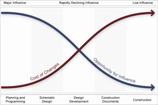
The most cost-effective time to make changes is during programming. This phase of a project is the best time for interested parties to influence the outcome of a project.
The "whole building" design approach is intended "to create a successful high-performance building." To achieve that goal, we must apply the integrated design approach to the project during the planning and programming phases. People involved in the building design should interact closely throughout the design process. The owner, building occupants, and operation and maintenance personnel should be involved to contribute their understanding of how the building and its systems will work for them once they occupy it. The fundamental challenge of "whole building" design is to understand that all building systems are interdependent. (Source: WBDG Web site, the goal of "Whole Building" design).
According to standard AIA agreements, programming is the responsibility of the owner. However, the owner's programmatic direction can vary from vague to very specific. In some cases, the owner does not have the expertise to develop the program and must use the services of a programming consultant. Most programming consultants are either architects or have architectural training, but others have become skilled through experience. Many architects perform programming as an additional service to their standard contracts. Many building type consultants (laboratory, health care, theater, etc.) have expertise in programming components of facilities.
Programming may happen for different purposes and may impact the level of detail of investigation and deliverables. For instance, programming at the master planning level is more strategic in nature—providing information to building owners to make decisions regarding current and projected space needs and rough budgeting for implementation. Programming at the individual project level provides specific, detailed information to guide building design.
The following discussion is intended to provide a clear process for conducting the research and decision-making that defines the scope of work for the design effort. It is imperative that the major decision-maker—the client-owner—allows participation of all of the stakeholders, or the client-users, who are affected by the design. Experience has shown that client-users' involvement in the programming process results in designs that can be optimized more efficiently.
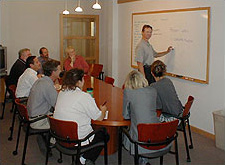
Design programming should involve the parties that are affected by the design solution.
Prior to the beginning of the process of programming a project, the programmer and the client-owner develop a list of the stakeholders to be involved. One organizational method is to form a Project Programming Committee with representatives from the stakeholder groups. For example, if the project is to be an office/classroom building for the humanities department at an institution of higher education, the Project Programming Committee could include representatives from the involved academic department(s), faculty, students, and building operations and facility maintenance departments.
Lines of communication must be established to determine how and when meetings will be called, what the agenda will be, how contacts will be made, and how records of the meetings will be kept. The authority of the committee must be made clear. In the example above, the committee's authority will be to make recommendations to the college authorities. Within that framework, the committee must decide how it will make decisions as a committee (by consensus? majority rule? other means?).
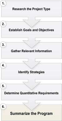
Many different programming formats incorporate the same essential elements. In all cases, the design programming fits within a larger context of planning efforts which can also be programmed. For design programming for a building, we propose a six-step process as follows:
This step is necessary if the programmer is working on a project type for the first time. The programmer should become familiar with some of the following relevant information:
This information can be obtained from literature on the building type, analysis of plans of existing projects, expert consultants familiar with the building type, and/or cost estimating services.
Working with the committee, the programmer solicits and suggests broad goal statements that will guide the remainder of the programming process. (See Design Objectives on the WBDG Web site.) Each of the following categories of goals should be addressed:
Based upon the goals, the categories of relevant information can be determined and researched. Typical categories include:
Programmatic strategies suggest a way to accomplish the goals given what one now knows about the opportunities and constraints. A familiar example of a programmatic strategy is the relationship or "bubble" diagram. These diagrams indicate what functions should be near each other in order for the project to function smoothly. Relationship diagrams can also indicate the desired circulation connections between spaces, what spaces require security or audio privacy, or other aspects of special relationships.
Other types of strategies recur in programs for many different types of projects. Some examples of common categories of programmatic strategies include:
Ideally, each of the goals and objectives identified in Step 2 will have some sort of strategy for addressing that goal. Otherwise, either the goal is not very important, or more discussion is required to address how to achieve that goal or objective.

Cost, schedule, and affordable area are interdependent. Costs are affected by inflation through time. Affordable area is determined by available budgets.
In this step, one must reconcile the available budget with the amount of improvements desired within the project time frame. First, a list of spaces is developed to accommodate all of the activities desired (see Exhibit A). The space criteria researched in Step 3 are the basis of this list of space requirements. The space requirements are listed as net assignable square feet (NASF), referring to the space assigned to an activity, not including circulation to that space.
A percentage for "tare" space is added to the total NASF. Tare space is the area needed for circulation, walls, mechanical, electrical and telephone equipment, wall thickness, and public toilets. Building efficiency is the ratio of NASF to gross square feet (GSF), the total area including the NASF and tare areas. Building efficiency equals NASF/GSF. The building efficiency for a building type was researched in Step 1 and possibly Step 3. See Exhibit A for an example of space requirements.
The building efficiency of an existing space used by a client can inform the selection of the net-to-gross ratio. The example below of an office suite within an office building illustrates the areas of net assignable square feet and tare area. Notice that some space within an office is considered circulation, even though it is not delineated with walls. We call this circulation, "phantom corridor."
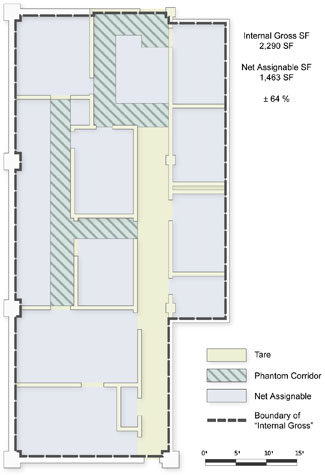
In the case of a tenant improvement within a larger building, one establishes the "internal gross" of the leased space. Additional support space or tare area such as mechanical rooms and public toilets would not be included in the calculation for this project type.
The desired GSF is then tested against the available budget (see Exhibit B). In drafting the total project cost, the programmer uses the cost per square foot amount researched in Step 1. Factors for inflation should be included, based upon the project schedule. Costs should be projected to the date of the mid-point of construction because bidders calculate estimates on the assumption that costs could change from the time of the bid date.
The total project cost includes the construction cost (for building and site work), plus amounts for architect's fees, furniture and equipment, communications, contingency, printing for bid sets, contingency, soils tests, topological surveys, and any other costs that must come from the owner's budget. The intention is to help the owner prepare for all the project costs, not just those costs assigned to construction.
If the bottom line for the project costs is more than the budget, three things can happen: 1) space can be trimmed back or delegated to a later phase (a reduction in quantity); 2) the cost per square foot can be reduced (a reduction in quality); or 3) both. This reconciliation of the desired space and the available budget is critical to defining a realistic scope of work.
Finally, once all of the preceding steps are executed, summary statements can be written defining "in a nut shell" the results of the programming effort. All of the pertinent information included above can be documented for the owner, committee members, and the design team as well. The decision-makers should sign-off on the scope of work as described in the program.
Once a program is completed and approved by the client, the information must be integrated into the design process. Some clients want the programmer to stay involved after the programming phase to insure that the requirements defined in the program are realized in the design work.
Some of the emerging issues in the discipline of architectural programming include:
A very important part of programming is identifying relevant codes and standards that apply to the project (see Steps 1 and 3 above). Codes, covenants, deed restrictions, zoning requirements, licensing requirements, and other legal obligations can have significant influence on costs and therefore, affordable GSF. These factors must be identified prior to design.
Many governments and institutions have developed standards and guidelines for space allocations. For example, the General Services Administration (GSA), military, and higher education institutions all have standards and guidelines. These standards must be adhered to in programming projects for these clients. The standards are also useful as guidelines for agencies that have not developed their own standards.
Some standards are mandated by statutes in some jurisdictions for licensing, accreditation, or equity purposes. Schools, hospitals, correctional facilities, and other licensed or accredited institutions may be required to meet these standards prior to opening their doors.
Some building codes identify the number of square feet allocated per person for certain types of occupancy. However, while these ratios may determine the legal occupancy numbers for the facility, exiting requirements, fire separations, etc., they represent the minimum requirements. It may be necessary to accommodate specific activities adequately with more space.
Case Studies, Federal Mandates
Cost Estimating for a discussion of conceptual cost estimating.
Cost-Effective for additional cost estimating software resources.
Graphic standards and other design standard sources:
In this example of space requirements, the list is divided into two parts representing space with significantly different construction costs.
Note that the Construction Cost, Line E, is significantly less than the Total Project Cost. The client needs to know what the total project will cost, not just the construction cost.
The modern profession of architecture echoes with its origins, its rich history, and the fast-paced changes of the 21st century. Through antiquity, architecture and construction were united by the cultural intentions of a "Master Builder," who balanced art, science, materials, form, style and craft to achieve his vision.
"The regulated profession of architecture is relatively new. Yet there have been architects for as long as societies have built, with little distinction between designers and builders. In ancient, traditional cultures and languages, the same word was used for both architect and builder. Construction was an integrated craft in which the master mason or master carpenter knew how to design, to assemble labor and materials, to estimate costs, to manage the construction process, and to erect structures from foundation to roof."
(Roger K. Lewis, p.149, from Architect? A Candid Guide to the Profession)
Roger K. Lewis illustrates that architects balance ideas, form, and function. Photo Credit: Roger K. Lewis
Beginning in the seventeenth century, with the rise of professionalism, the discipline of architecture became increasingly specialized. With the nineteenth century expansion of scientific knowledge, the evolution of other technically oriented disciplines such as engineering, and the corresponding introduction of more complex construction systems, the discipline of architecture became more focused on questions of basic functionality and aesthetics. In pursuit of professional status, architects wanted no longer to be perceived as craftspersons. During the 19th and 20th centuries, the profession made conscious efforts to distance architects from contractors.
This specialist role now forms the basis of most widely accepted modern definitions of architectural practice. For instance, the United States Department of Labor defines architects as licensed professionals who transform space needs into concepts, images, and plans of buildings to be constructed by others. Still, echoes of the "Master Builder" remain, as architects are usually responsible for orchestrating and coordinating the work of many disciplines during the design phases. It is not unusual for architects also to be involved in the early stages of project feasibility, to help clients define a program, choose the site, and otherwise decide on highest and best uses.
The discipline of architecture has both legal and cultural definitions. In the United States, all states have regulations that govern conditions of licensure, registration, use of the title "architect" and the provision of professional services, succinctly summarized by The American Institute of Architects. Each state or jurisdiction creates its own requirements for each of these aspects of the discipline. While legal definitions mandate the ways in which the profession is responsible for safeguarding the health, safety, and welfare of the public, cultural definitions characterize the ways in the discipline responds to social, aesthetic, and ethical aspects of making cities, buildings, and landscapes. A "whole building" approach must necessarily incorporate both sets of disciplinary definitions.

Sometimes beauty and functionality are in tension, as seen by Roger K. Lewis. Photo Credit: Roger K. Lewis
Today, the required legal, technical, and cultural knowledge base has such breadth and depth that it is no longer in the best interest of the project for one discipline to hold, implement, and be responsible for all building-related knowledge, as did the Master Builder of old. Professional malpractice concerns have led liability insurance companies to encourage, even implicitly force, architects to limit activities to design. For example, "construction supervision" became "construction observation," moving the architect further away from the risks associated with construction activities.
According to some industry analysts, such as Carl Sapers, the architect's role has been further limited by the idea that buildings are commodities, consisting of assemblies of standard materials and systems best understood by their suppliers and constructors. New forms of project delivery, including "design/build", "bridging", and "construction management", come out of a belief that architects are no longer able to stay abreast of complex information in order to lead the design process on the owner's behalf. (Carl Sapers, "Toward Architectural Practice in the 21st Century," in Harvard Design Magazine, Fall 2003/Winter 2004)
However, this standardized approach to efficient building design is not necessarily synonymous with the requirements for whole building design. Integrated, high-performance design requires both efficiency and innovation. It requires a design process in which the users, owners, and project participants are all integral team members.
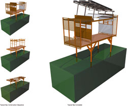
An innovative approach to efficiency: a prefabricated structure for an ecologically-sensitive site. Kingman Island Environmental Education Center competition finalist. Photo Credit: University of Maryland School of Architecture, Planning, and Preservation
With whole building design, the project team can be guided once again by a collective vision. This structure, along with the process by which the design team works together, has been termed by Bill Reed as the "Composite Master Builder". The term recasts the historical single Master Builder as a diverse group of professionals working together towards a common end. The intention is to bring all of the specialists together, allowing them to function as if they were one mind. The process avoids, as Mario Salvadori says, the "reciprocal ignorance" of the specialists in the design and building field.
The cast of specialists is potentially quite large, and depending on the complexity of the project, can include:
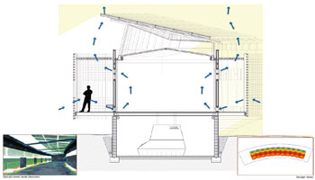
A cast of specialists worked together to design building systems using the building section as a tool. Kingman Island Environmental Education Center competition finalist. Photo Credit: University of Maryland School of Architecture, Planning, and Preservation
The legal obligations of the profession, comprehensive training in holistic problem-solving, and an understanding of broad cultural concerns make architects ideally suited for the leadership of design teams.
Architects in the United States have historically been bound by comprehensive legal requirements and responsibilities for the building design. They are legally obligated to safeguard the public health, safety, and welfare. This presumes that architects maintain at minimum a clear overview of the project team's work. Arguably, the most effective way to discharge this public duty is to oversee and coordinate the work of the project team.
The profession emphasizes comprehensive training in the arts and sciences, as well as a holistic approach to design problems. Architectural education teaches both abstract and concrete problem-solving. Its core skills are learned and re-learned, in an iterative process that incorporates history, theory, technology, and other social and cultural factors. Architects are both specialists and generalists, which ideally enables them to communicate effectively with other specialists while maintaining the "big-picture" view of the project goals.
In addition to health, safety, and welfare considerations, buildings incorporate the culture that created them. The built environment is both "mirror and lamp", shaping while acting as a repository of cultural meaning. As Churchill said, "We shape our buildings; thereafter they shape us." With their knowledge of the arts and culture, architects hold a comprehensive understanding of the project context and can help the design team move beyond mere problem-solving.
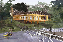
Holistic building design comes out of a comprehensive understanding of the project context. Kingman Island Environmental Education Center competition finalist. Photo Credit: University of Maryland School of Architecture, Planning, and Preservation
As leaders and participants in the design process, architects need to understand and work collaboratively with other disciplines. To this end, architects need to pursue education and training throughout their professional careers. Many excellent examples of interdisciplinary design studios exist in the United States. These studios involve students, faculty, practicing design and engineering professionals, and even clients and regulatory officials. Some studios participate in service-learning projects to build structures for deserving clients. Everyone involved—students, professionals and members of the community—benefits from the process itself, as well as the cross-pollination of ideas and techniques. Examples include Studio 804 at the University of Kansas School of Architecture and Urban Design, and Architecture 600 Integrated Design Studio V at the University of Maryland's School of Architecture, Planning, and Preservation.
Continuing education is a lifelong endeavor for practicing architects and is mandated in many jurisdictions, as well as by The American Institute of Architects (AIA). Typically, this education involves technical training, management courses, legal and liability issues, and learning about new materials and products. The practice of seeking out training in the various aspects of leadership of an integrated design team, such as workshop facilitation, is not yet common. However, critical skills are needed to assume this role, which was addressed in a recent article in Environmental Building News. Current practitioners of integrated design, such as Terry Brennan of Camroden Associates, observe that architects have the intention to become cooperative but lack the skills. "The lead designer must be skilled in nurturing and giving form to the collective vision, rather than expressing his or her own vision. Not all architects are comfortable with this role, which is more akin to that of a midwife than to that of an individual artist." (EBN, November 2004, "Integrated Design" feature article)

Project charrettes for the Kingman Island Environmental Education Center establish early and regular interaction among design team members. University of Maryland School of Architecture, Planning, and Preservation
In daily practice, early and regular, structured interaction of the "Composite Master Builder," is critical to establishing a project vision and maintaining momentum throughout the design and construction process. Activities might include charrettes, workshops, peer review, and post-occupancy review.
The whole team interaction focuses on collaborative, integrated problem solving, to address issues such as:

Roger K. Lewis' view of emerging issues. Photo Credit: Roger K. Lewis
The context of architectural practice is always evolving. Beginning with the subject of buildings themselves, the cataloguing of building types is a practice as old as the discipline. It is common to see evolution of building and program types, and adaptive reuse of waning types, as a mirror of a culture. Building types evolve in response to cultural change—new programmatic needs, recent events that challenge norms of an equitable accessibility as well as secure facilities and environments, and changes in practice to accommodate a diverse populace. Department stores, train stations, shopping malls, airports, high-rise apartment buildings, living machines, and recycling centers have changed our building and urban landscapes.
Evolutions in current architectural practice also include a re-commitment to community and public service, and an abiding interest and concern for our cities and landscapes. Both find articulation in "smart growth" initiatives, inventive real estate investment and development schemes, urban redevelopment, and trends in the historic preservation of cities and buildings. Additionally, cultural preservation is seen as equally important to building fabric preservation and conservation. Sustainable design takes these concerns further in advocating a beneficial relationship between the built and natural environments.
Cultural preservation and resource conservation in action at the Bradley residence, designed by Amy E. Gardner AIA. Photo Credit: the authors
In the Brown residence designed by Julie Gabrielli, sustainable design takes a "cradle-to-cradle" view, combining antique timbers with 21st century technologies—a "wondrous hybrid". Photo Credit: the authors
In fact, the tilt towards a sustainable practice might well be thought of as an expected standard of practice, encompassing issues such as those connected to planning, zoning, and building codes; building science and performance; energy sources, management, and use; material resource management, science, and invention; and broad concepts of waste and renewal of natural and technical systems. Discussions of these concepts is persuasively argued by William McDonough and Michael Braungart in Cradle to Cradle.
Globalization of practice, especially as it relates to changes in the workforce, labor, and practice, has the potential to dramatically change the discipline. The outsourcing of design and drawing labor overseas; the robotic manufacturing of building components and materials; and the use of sophisticated three-dimensional computer programs to design buildings raise questions and challenge current modes of project delivery. Trends in computer-aided building design and manufacturing figure prominently in any discussion of project delivery methods.

Norman Foster's Swiss Re Headquarters in London demonstrates sophisticated building technologies developed through advanced modeling systems.
A significant current trend in computer programs for building design and documentation, for example, is the move towards Building Information Modeling. The initial purpose of computer drawing systems was to automate two dimensional drafting. It did so through representing three dimensional building elements with an assemblage of two dimensional symbols such as lines. However, Building Information Modeling (BIM) is an object-oriented CAD system, in which two-dimensional symbols that stood for building elements are replaced by three-dimensional objects with embedded information, capable of representing elements of construction. This allows for multiple views to be generated, for multiple building systems to be coordinated, for materials and quantities to be known and referenced to each other, all during the design and documentation phases of a project. These qualities allow for a degree of interconnectedness during design and documentation phases not readily achievable in two-dimensional CAD systems.
Industry experts predict that BIM will revolutionize not only the delivery of design and documents, but also the relationship between design team members, owners, and construction entities and the relationship between design and construction activities. However, Ken Sanders, FAIA, observes in the September 2004 issue of Architectural Record: that "the critical path isn't BIM, but rather process innovation squarely focused on people, partnerships, shared expertise, and timely decision making." Nevertheless changes in the way that design teams conceive, develop, and communicate information about buildings are positioned to have a dramatic impact on the practice of architecture.
Architectural projects can be executed through a variety of project delivery methods. Prior to the twentieth century, there was a single project delivery method—the architect won a commission, produced drawings for design and construction, pulled labor and materials lists together, and oversaw the building of the project. As architects moved the discipline towards a profession and away from a craft, different project delivery methods developed to accommodate the changing relationship between architects and craftspeople.
Currently, three project delivery methods dominate in the United States: design-bid-build, design-build, and construction management. In order to assist owners and the construction industry by establishing accepted definitions of project delivery methods, the AIA and the Associated General Contractors of America jointly created a document entitled "Primer on Project Delivery", offering information on these methods for owners and architects. However, each method may be summarized to capture a flavor of the intent. Design-bid-build is a method by which project delivery is separated into three distinct phases: a project is designed and documented with drawings and specifications, competitively bid to multiple general contractors, and then built by the general contractor, guided by a contract with the owner of the project. Design-build is a project delivery method in which a single entity (for example a general contractor in a joint venture with a design team including architects and engineers) holds a single contract with an owner for both the design and construction of a project. Finally, the construction management method is a process that involves the coordination and management of the entire process via a single entity—from site survey through occupation. It encompasses the evaluation, selection, and management of all contractors, as well as the administration of the project budget relative to the implementation of design.
Project management is also a significant term within architectural practice. In the execution of a project, the work of all disciplines and relationships needs to be orchestrated—architectural design, the coordination of other design disciplines, team members' design and drawing work, client relationships, time and fee tracking, to name a few. This orchestration is achieved through the architectural project manger, a conductor of sorts. The goals of project management include the orchestration and integration of an overlapping set of issues including project scope, schedule and budgets, development of the design, management of the delivery team throughout the various phases of the project from inception to initial occupancy.
Both project delivery methods and internal project management roles are evolving in a manner commensurate with evolutions in digital technologies, building technology, and construction case law. Similarly, contracts evolve following events in construction and professional case law. Currently, more than 90 documents authored by The American Institute of Architects constitute an industry standard for contracts and project administration forms—according to the AIA, "a significant body of case law concerning contracts for design and construction is based largely on the language of AIA standard forms."
The changing context of architectural practice points to challenges to and opportunities for whole building design. Evolutions such as BIM have the potential to facilitate—or further complicate—integrated work. Areas of evolution should be carefully analyzed for potential avenues for integrated rather than episodic action, allowing the objectives of whole building design to be met in a holistic fashion.

Roger K. Lewis captures the complexity and magnitude of code requirements. Photo Credit: Roger K. Lewis
Since at least the Code of Hammurabi in the 18th Century BC, there have been codes governing the design and construction of buildings. While Hammurabi had rather onerous requirements for quality (for instance, if the owner is killed by a building, its builder is sentenced to death), many subsequent codes were established in reaction to dramatic events such as fires, earthquakes, and floods. Some codes, such as the Code of Napoleon, 18th Century AD, provided for loss replacement as a sort of insurance policy. Still other codes established rules for materials or systems: the Lord Mayor of London in 1189 required party walls between buildings, and the Charlestown General Assembly in 1740 required brick and stone for exterior walls.
Until recently, most building codes have been prescriptive, effectively casting design professionals in the role of negotiators between the owner's ideas and the realities of codes. High-performance, integrated building design recently started leading design teams away from this "just barely legal" approach. As a tool to aid in this process, the new performance-based building codes give the design team more flexibility in meeting requirements.
The international Code Council (ICC) was formed from the joining of publishers of National and Standard Building Codes, Building Officials and Code Administrators International, the Southern Building Code Congress International, and the International Conference of Building Officials. The result of their merging was the International Code Series—part of the U.S.'s first unified comprehensive and coordinated building codes.
A. U.S. Code Organizations:
B. Codes:
Many of these organizations have voluntary standards for quality assurance. Others publish standards that are referenced by the LEED Green Building Rating Guide, for meeting requirements of various credits.

Resources are central to a knowledge-based practice of architecture. Photo Credit: Roger K. Lewis
See: Professional Organizations above
Acknowledgements
–Credit and gratitude to Roger K. Lewis FAIA for wisdom, insight, and the use of his cartoons
–Credit and gratitude also to George Holback AIA for the ideas in the section on the the History of Building Codes
Archives and Record Storage buildings are facilities that provide a proper environment for the purpose of storing records and materials that require permanent protection for historic and lifetime storage, upkeep, and preservation. Archives and Record Storage buildings must be high-performance with systems designed to operate permanently at a very high level with zero tolerance for failure. The often irreplaceable nature of the materials to be permanently stored and preserved in this type of building requires a life-cycle analysis and approach to its design and construction, with extensive redundancy in its building systems.
This building type must be designed to accommodate the loads of the materials to be stored; the sensitive environmental needs of different materials to be permanently stored and preserved; the functional efficiency, safety, security, and comfort of the visiting public and operating personnel; and the protection of the archived materials from fire, water, and man-made threats.
To accomplish this complex mission, these buildings benefit from an inclusive, holistic, integrated or whole building design approach that optimizes and balances the various design objectives to achieve the desired high-performance building. This process involves all building stakeholders and design professionals from the beginning of the project and throughout every other project phase. See WBDG Engage the Integrated Design Process.


The National Archives building in Washington, DC was designed by renowned architect John Russell Pope as a temple to history and was completed in 1935. Pope wanted the architecture of the National Archives to reflect the significance, security, and permanence of the records held therein. Photo Credit: National Archives Museum
The majestic domed ceiling of the Rotunda, rising 70 feet above the floor, and 40-foot-tall bronze doors contribute to the feelings of awe and reverence experienced by visitors to this magnificent space. For more information on the history of the building click here. Photo Credit: National Archives Museum
An Archives and Record Storage building must have working environments that are safe, secure, healthy, comfortable, durable, aesthetically pleasing, and be accessible. Administrative office space, archival and preservation office space, and permanent storage space for the stored archival and record materials must be accommodated. Important design issues for Archives and Record Storage Buildings are:
An Archives and Record Storage building incorporates a number of space types to meet the needs of staff and visitors. These spaces and their attributes may include:
Shelved record boxes of an archive. Photo Credit: Wikipedia, CC BY-SA 3.0
Typical features of Archive and Record Storage buildings include the list of applicable design objectives elements as outlined below. For a complete list and definitions of the design objectives within the context of whole building design, click on the titles below.
Design of storage buildings is challenging because they tend to be large massive structures with vast expanses of featureless wall surfaces. Aesthetics may focus on several considerations:
The high-performance Archives and Record Storage building should be evaluated using life-cycle economic and material evaluation models. The mission of this building type is to preserve valuable materials and records for a long duration. Design and construction of such a building is imperative to mission performance and savings on long-term operations and maintenance.
The design process should include analysis of cost benefits and tradeoffs between various storage systems and methods, structural loading designs, amount of built floor space, and future expansion needs. See also WBDG Functional / Operational.
To achieve the optimum performance for the investment in the facility, value engineering provides a means for assessing the performance versus cost of each design element and building component. In the design phase building development, properly applied value engineering considers alternative design solutions to optimize the expected cost/worth ratio of projects at completion. Value engineering elicits ideas on ways of maintaining or enhancing results while reducing life cycle costs. See WBDG Cost-Effective—Utilize Cost and Value Engineering Throughout the Project Life Cycle.
Because storage methods can greatly affect building design and costs, the design team should include expertise on storage systems and archival materials handling. Such expertise should also be included on a value engineering team during the design phase.
Archive and Record Storage buildings must contain flexible storage arrangements to house growing collections of materials with varying storage and environmental requirements. Floors may be designed for 150 pounds per square foot (psf) live load to allow the arrangement of standard full-height shelving anywhere in the library. Since future growth may require shelving to be relocated, 150 psf design loads will allow the standard full-height shelving to be placed anywhere without being concerned about potential structural damage from excessive point loads caused by overloaded shelves. However, increasing the design load to 300 psf allows high-density compact shelving, as opposed to standard shelving, to be placed anywhere. Compact shelving houses a greater quantity of media than standard shelving.
The design process should include analysis of cost benefits and tradeoffs between various storage systems and methods, structural loading designs, amount of built floor space, and future expansion needs. See also WBDG Functional / Operational.
Movement between archive spaces must be convenient, logical, and efficient. Walls and columns must be located efficiently and designed to facilitate future expansion. Future growth and expansion should be taken into consideration in the design program at the onset. See also WBDG Functional / Operational—Account for Functional Needs, Productive—Design for the Changing Workplace, Accessible—Beyond Accessibility to Universal Design.
Consider high ceiling heights to accommodate vertical high-density storage to offset increase of building footprint and enable easier future vertical expansion. As collections grow, storage/shelving space decreases. As a result, compact shelving must be included in any design. Storage of periodicals or government documents in compact shelving has become common practice.
Adequate space for storage, preservation, and repair of electronic information and media systems should be included in the program. See also WBDG Productive—Integrate Technological Tools.
Include space for staff and researcher use of electronic technologies. The space needs for workstations mimic that required to accommodate office workstations at 30 to 50 square feet for each. See also WBDG Productive.
If archives are stored on more than one floor, vertically align mechanical and electrical service spaces to eliminate horizontal runs across archive spaces.
Design vertical riser shafts with sufficient space for future expansion and adoption of future technologies.
Worker Satisfaction, Health, and Comfort: By far the greatest life-cycle costs of a building are the salaries and benefits of the occupying employees, which generally exceeds the lease and energy costs of a facility by a factor of ten on a square foot basis. For this reason, the health, safety, and comfort of employees in a high-performance building are of paramount concern.
Utilize strategies such as increased natural ventilation rates, the specification of non-toxic and low-polluting materials and systems, and indoor air quality monitoring. Consider separately exhausted or separated space for air-polluting materials used in any archival preservation process.
Individualized climate control in office spaces that permits users to set their own, localized temperature, ventilation rate, and air movement preferences is desired. However, critical requirements for archival material may require a constant environment.
While difficult to quantify, it is widely accepted that worker satisfaction and performance are increased when office workers are provided stimulating, dynamic, working environments. Access to windows and views, opportunities for interaction, and control of one's immediate environment are some of the factors that contribute to improved workplace satisfaction. See also WBDG Psychosocial Value of Space.
The acoustical environment of the office must be designed and integrated with the other architectural systems and furnishings of the office. Special consideration must be given to noise control in open office settings, with absorptive finish materials, masking white noise, and sufficient separation of individual occupants.
Consider worker ergonomics and safety with regard to frequency of need to access certain archival materials and storage method used. Storage systems should discourage the need for ladders and heavy lifting.
Technical Connectivity
Technology has become an indispensable tool for organizational operations and security. Given that technology is driving a variety of changes in organizational and architectural forms of buildings, consider the following issues when incorporating technology, particularly information technology (IT), into a building:
Plan new buildings to have a distributed, robust, and flexible IT infrastructure, which would allow technological access in virtually all the spaces. Restrict conduit penetrations to perimeter of fire-protected archive storage spaces.
During the planning stage, identify all necessary technological systems (e.g., voice/cable/data systems such as audio/visual systems, sensing and alarm systems, speaker systems, Internet access, and Local Area Networks [LAN] / Wide-Area Networks [WAN] / Wireless Fidelity [WI-FI]), and provide adequate equipment rooms and conduit runs for them.
Consider and accommodate wireless technologies, as appropriate.
For existing buildings, consider improving the IT infrastructure and access for future flexibility as renovations are undertaken. See WBDG Productive—Design for the Changing Workplace and Productive—Integrate Technological Tools for more information about incorporating IT into facility design.

The Milton Public Library in Milton, Ontario joined Open Libraries and donated 30,000 books to the Internet Archive in response to the pandemic in 2020 to make material more accessible to the public. Photo Credit: Internet Archives Blog
Natural and man-made threats of the last decade have focused attention on protection of occupants and assets. Through comprehensive threat assessment, vulnerability assessment, and risk analysis, security requirements for individual buildings are identified, and appropriate reasonable design responses are identified for integration into the building design.
Given the mission of this building type, protection of occupants, assets, and building contents is of paramount importance. Protection of valued archival materials from fire and smoke, water, and inadequate environmental conditions, will require robust building and systems design, and reliable, durable, and integrated system sensors, monitors, alarms, and protection devices. In addition man-made threat security shall require controlled access and surveillance systems.
Consider entrances that do not face uncontrolled vantage points with direct lines of sight and driveway access to the entrance.
Utilize site barriers and setback distance, perimeter barriers and blast resistance, access control and intrusion detection, entrance screening, package screening and control, open areas that allow for easy visual detection by occupants, and minimized exposed glazing. See WBDG Secure / Safe—Security for Building Occupants and Assets.
Major circulation patterns should be clearly understood and logical. First-time visitors may have trouble navigating the safest exit route from the building. Consider using increased signage and/or providing safety information and a building directory in welcome brochures or on the facility's website. Also, review and evaluate safety plans on a regular basis. See WBDG Secure / Safe—Fire Protection and Secure / Safe—Occupant Safety and Health.
Fire protection system design becomes a critical design element involving extensive fire-rated construction and pressurized water delivery to sprinkler or water mist systems. Locate water main piping outside archive storage space to the extent possible. Fire protection systems must be designed to put out a fire as quickly as possible with minimal collateral damage to structure and contents.
Also include ability to rapidly vent heat and smoke from fires. This may be difficult to achieve for archive and record storage facilities located in basements and underground caverns.
If the program calls for multistory archive storage, consider the impact on fire fighters to access the fire, and to vent heat and smoke from upper stories.
Provide backup systems for all critical building functions for occupant safety and preservation of archival contents.
Consider synergies between sustainable strategies to conserve energy and right-sizing of security and emergency backup systems. See WBDG Balancing Safety/Security and Sustainability Objectives.
Sustainable design depends on building size, local climate, use profile, utility rates and discounts, and many other factors. Design strategies to achieve sustainability may involve:
Given the large roof and floor areas typical for this building type, consideration should be given to green or cool roof design, the application of alternative or renewable energy systems such as building-integrated photovoltaic systems to generate electricity, solar thermal systems to produce hot water for domestic hot water (DHW) or space conditioning, or geothermal heat pump systems to improve HVAC system performance.
Additional consideration should be given to the applications of other distributed energy sources, including microturbines, fuel cells, etc., that provide reliability (emergency and mission critical power) and grid-independence, and reduce reliance on fossil fuel grid power.


The National Archives II in College Park, Maryland, is the largest and most technically advanced archives building in the world. Designed by HOK architects and Ellerbe Becket engineers, the 1.8 million sf building includes records processing and storage areas (stacks), a five-level research center, conservation and special media laboratories, offices, conference, and training facilities, an auditorium, a cafeteria, a day care center, and an exercise facility. The central focus of the Archives II design was to create a building with state-of-the-art systems and environments that adhered to the strict conditions necessary for the long-term protection of records. Special attention was given to the design and construction of the records storage environments, the mobile shelving system, fire protection, and security. In addition, the finishes and materials used in the construction of the stacks were carefully studied and selected to minimize the exposure of the records to harmful contaminants. Photo Credit: Archives.gov
Given the long-term perspective required for an archives facility, the building will have to accommodate changing technologies for storage and handling of archival materials, change in the nature of the stored materials themselves, changes to building systems and materials over time, and possible change or redefinition of mission. See WBDG Productive—Design for the Changing Workplace and Productive—Integrate Technological Tools.
Electronic Media—The program should provide adequate space for housing and use of digital materials as more record storage is now being preserved in electronic form. Magnetic materials and optical storage media require specialized storage for conservation and preservation. Archival collections should receive special treatment and handling, and require specialized space temperature and humidity environments for preservation and storage.
Educational/Teaching Function—Consider program needs for outside group educational and teaching space(s), and for internal facility staff training and educational space(s). Such learning centers must be supported by access to electronic information resources, hardware tools, and associated productivity software. Consider implementing wireless communications technologies to allow archival staff to classify and locate archival materials using bar code technology without being bound to a desk.
Commissioning—With improved and complex building technologies and controls it is crucial that high-performance buildings are properly commissioned as part of a comprehensive quality assurance plan. The process of ongoing commissioning over the building life-cycle has shown to be effective. Federal agencies and private institutions are moving aggressively in the direction of mandating commissioning for all high-performance structures in their portfolios.
Modernization—An extensive inventory of older Archive and Record Storage facilities represents significant modernization challenges. Key areas of concern include: upgrading the exterior envelope, mechanical systems, telecommunications infrastructure, security, and interior finishes. Improving the workplace quality, energy performance, security, flexibility to accommodate tenant churn, maintenance overhead, and life-cycle expectancy are important objectives for modernizing these facilities. Appropriate preservation for buildings on, or eligible to be on, the historic registry is part of the modernization effort.
Libraries, Academic Library, Presidential Library, Office Building, Parking Facilities, Warehouse
Atrium, Auditorium, Automated Data Processing: Mainframe, Automated Data Processing: PC System, Conference/ Classroom, Food Service, General Storage, Library, Lobby, Mail Center, Office, Parking: Outside/Structured, Parking: Surface, Physical Fitness (Exercise Room), Private Toilet, Warehouse
Aesthetics, Cost-Effective, Functional / Operational, Historic Preservation, Productive, Secure / Safe, Sustainable
Building Commissioning, Determine Project Performance Requirements, Commissioning Document Compliance and Acceptance, Owner's Role and Responsibilities in the Commissioning Process
Following the Civil War, the U.S. government was becoming increasingly concerned over the possibility of widespread civil unrest and class warfare. This led to the authorization of fortified bases for local militia throughout the country by the United States War Department in 1877. Local Armory Boards were organized in many states and cities, leading to the construction of numerous armories.
Newport, Rhode Island Armory, 1894
Many of the older armories were often ornate, fortress-like structures. The predominant turn-of-the-century architectural philosophy was that a building should proclaim its purpose. "A church should be welcoming, a jail should be oppressive, and an armory should be strongly suggestive of a fortress." (Dr. John H. Lienhard, Professor Emeritus, University of Houston, The Engines of Our Ingenuity, Episode No. 822, Old Armories.1)
The original function of armories was to provide a protected location where local militia could gather and train, as well as store their arms and ammunition. The spaces usually contained a large open area to practice maneuvers, offices, classrooms, dining facilities, weapons storage, and other support operations.
Today, armories, sometimes referred to as readiness centers, are used by National Guard and military reserve units. Their primary function is still to provide spaces for training, administration, and material storage for the assigned military units. Armories are also utilized to respond to emergencies and support state disaster relief for floods, fires, snowstorms, tornados, water outages, etc. In addition they are often used as a local community resource to house social functions such as public meetings and sporting events.
As institutional buildings, the primary consideration in the planning or design of an armory is to ensure a highly functional, operationally efficient facility. Other important considerations are to provide a safe, flexible, cost-effective, energy efficient facility that is aesthetically pleasing and comfortable to the occupants.

Westerly Armory, Rhode Island, 1901–1902, Photo Credit: Victoria Lague
The functional requirements and intended usage of individual armories may vary considerably. The information contained herein is intended to summarize general information and guidance typical for most armory facilities. Each project should be developed individually considering specific project requirements, local conditions, and codes in order to arrive at the appropriate design solution.
An armory is primarily used as training facility on both an individual and a unit level. The facility consists of a training center and may also include a related maintenance area.
Training Center: The training center generally consists of four main functional areas; administration, classroom, assembly, and unit storage, as well as general and an special support areas:
The office spaces are intended for the training of clerical personnel, performing necessary paperwork, and administration activities. These functions can be separated into spaces dedicated to unit supervisors and full-time employees and common spaces shared by non-supervisory personnel that may be used by different individuals as the units rotate through training cycles.
Administration support spaces include message centers, reproduction rooms, conference rooms, and administration storage. The requirements for these spaces will depend upon the needs of the individual armory. Message centers serve as a mailroom and distribution point for all inter- and intra-office correspondence. A safe or other secure space for the storage of sensitive communication devices may also be required. Additional support spaces such as conference rooms, reproduction areas, drafting rooms, or photo labs may also be desirable.
Classrooms should be located close to an outside entrance for easy access without going thorough the administration area. Depending on the specific nature of the anticipated instruction, the designer shall consider the specific features including size, sound attenuation, lighting, and equipment such as desks, blackboards, audio/video devices, moveable partitions, etc.
Specialty learning centers may be required to provide focused occupational specialty training utilizing audiovisual equipment.
The library/classroom provides a space for storing training publications and training related material, as well as a reading area and space for a small conference classroom.
Additional storage space may be provided for miscellaneous training materials.
The assembly hall provides space for troop formations, maintenance of equipment, food service seating, and large group assemblies for instructional training. It also may serve the neighboring community as a place of public assembly for planned functions as well as for a place of refuge in the event of natural disasters. These latter functions may control the design when considering fire protection requirements, accessibility, and bathroom layout. The assembly hall is an important functional element and should be centrally located within the facility, immediately adjacent to the kitchen and food storage spaces.
Chair storage space may be a separate room opening onto the assembly hall or a part of the assembly hall.
Unit Storage Area: Storage areas include spaces to manage the inventory of organizational equipment in a separate and secure area. The issue and return of organization clothing and equipment is conducted from this area that consists of a supply office and storage area subdivided by woven welded wire fabric. Locker spaces may also be provided for individuals to store clothing and equipment.
General Support Areas: General support areas include toilets and showers, mechanical equipment, electrical equipment, telephone equipment, janitorial and facility maintenance storage.
Special Support Areas: Special areas may be required based on functional requirements and include arms ranges and vaults, trainers and simulators, medical services, photo lab, etc.
Arms Vault/Armory Rooms: The arms vaults provide secure storage of all weapons and ammunition assigned to the facility. The vault should be located adjacent to the firing range and not on an exterior wall if possible. Special security and construction considerations must be addressed.
Security: An intrusion detection system (IDS) shall be installed, or provided for, according to the applicable criteria. (DOD 5100.76-M requires IDS for all DOD facilities storing category I and II missiles and rockets, category I and II ammunitions and explosives, and category II, III, and IV arms unless the storage areas are continuously manned or under constant surveillance.)
Minimum Construction: (Note: Minimum construction requirements vary between agencies. The minimums stated below are for U.S. Army Reserve Facilities.)
Walls: Minimum of 8 inches of concrete reinforced with a minimum of #4 at 9 inches on center in each direction. Reinforcement shall be in each face and staggered to form a grid approximately 4½ inch square. (DOD 5100.76-M also allows 8-inch filled concrete block reinforced with #4 or 8–inch interlocked brick for DOD facilities.)
Ceilings: Minimum 8 inches of concrete reinforced with a minimum of #4 bars forming a grid such that no opening exceeds 96 square inches.
Structural floors: Minimum 8 inches of concrete reinforced with a minimum of #4 bars forming a grid such that no opening exceeds 96 square inches.
Slabs on Grade: Minimum of 6 inches of concrete reinforced with welded wire fabric 6 x 6 / W10 x W10
Doors: Vault Doors shall be Class 5, Federal Specification AA-D-600B. (DOD 5100.76-M allows a solid hardwood or laminated wood door at least 1–¾-inch thick with a 12–gauge steel plate on the outside face, or a standard 1–¾-inch thick hollow metal, industrial-type door with a minimum 14–gauge skin plate thickness, internally reinforced with continuous steel stiffeners spaced 6 inches on center.)
Locks: Class 5 vault doors have built in combination locks. Other doors shall have a high security lock and hasp per the applicable criteria.
Modular Vaults: Modular vaults meeting Federal Specification AA-V-2737 may also be considered if acceptable to the design agency.
Weapons Storage containers: Weapons Storage containers shall be GSA approved Class 5.
Arms Range: The design and construction of arms ranges shall be according to the appropriate criteria and/or definitive designs. Specific design considerations may include the following:
Ventilation: All applicable OSHA and safety environmental regulations must be satisfied. It essential to ensure laminar airflow with an adequate air speed evenly distributed across the entire cross section of the range at the firing line. (Due to the difficulties of meeting environmental requirements it is strongly recommended to use a proven design, and that all new or renovated ranges require a qualified testing firm perform an evaluation of the ventilation system in the completed range to ensure adequacy prior to acceptance.)
Bullet Trap: Escalator, Venetian Blind type
Target Retrieval Mechanism: Manual or automatic
Acoustical Material: On the side walls and ceiling and extending down range of the firing line
Floor Drains: A floor drain and hose bib for washing the range floor may or may not be allowed. Prevention of the release of environmentally hazardous substances must be considered in the design.
Medical Services: Medical spaces provide spaces for physical exams, treatment and professional medical training. Where required, these spaces shall be designed for the specific intended requirements.
Photo Lab / Soils Testing Lab / SCIF, etc: Where required special functional areas shall be provided for training in photography developing and processing, soils testing, electronic intelligence, etc.
Maintenance Area: The maintenance area, if required, contains the spaces used to service, maintain, and store the organizational equipment as well as to train reserve mechanics. The area may contain shop offices, work bays, tools and parts storage and issue, equipment and vehicle storage, battery charging and storage, flammable material storage, mechanical equipment room, and personnel spaces including toilet, lounge, and locker rooms. There also may be requirements for special areas including small arms shop and vault and electronic/communication repair shop.
The maintenance area may also require spaces for the storage of heavy vehicles and equipment that are used during training periods. This area may contain provisions for a parking hardstand, fuel dispensing system, loading ramp, wash platform, and an indoor equipment storage warehouse.
The following diagrams depict a sample of the relationships between the functional areas of both the training center and a maintenance area within an armory.
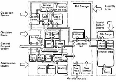
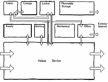
Sample — Armory Training Center Functional Relationship
Sample — Drive-through Maintenance Area Functional Relationship
Image credit: Department of the Army, Corps of Engineers, Design Guide DG 1110-3-107, U.S. Army Reserve Facilities, September 1984)
Armories are typically intended to be multipurpose facilities that may require the ability to change their training emphasis over its life. Therefore the design of an armory should consider incorporating internal flexibility to accommodate change without undue expense. External flexibility should also be considered to accommodate potential growth and anticipated future use requirements. Evaluation of the cost impact of design decisions should consider life-cycle cost as well as initial cost and building system flexibility.
Designs for armories shall consider the traditional life-safety and health concerns common to all buildings by following all applicable federal, state, and local building code guidelines.
A fire alarm and evacuation system shall be provided with illuminated exit signs and emergency lighting according to life-safety codes.
Comprehensive fire protection features and systems shall be developed for each project design.
If an indoor arms range is included in the facility, the design and construction must incorporate proven environmentally safe provisions to ensure adequate ventilation of potentially harmful fumes, to clean the facility, and properly contain and dispose of potential contaminants. Appropriate signage and operational procedures shall be established to clearly direct personnel to take appropriate precautions.
Appropriate security systems including potential fencing and intrusion detection measures shall be incorporated into the overall armory design.
All applicable state and/or federal standards for handicapped parking and accessibility shall be considered. All areas of a facility accessible to the public will typically be required to meet the accessible standards, when newly constructed or renovated, according to the standards set forth in the Americans with Disabilities Act Architectural Guidelines (ADAAG) unless a more stringent state requirement is to be applied.
Energy conservation opportunities shall be evaluated and incorporated into the design of all armories to the fullest extent practical. The most efficient and cost-effective systems, based on life-cycle cost, should be utilized. The following areas for energy-efficient design are recommended for consideration:

State National Guard Armory—Centerville, AL Photo Credit: Jonathan Bush
Armories should reflect characteristics of both a military facility representing national strength and patriotism, as well as a community support facility representing a sense of security, local pride, and community participation. Modern armories are generally designed to blend into the existing architecture of the surrounding region, and appear more like educational buildings than the fortresses of earlier armories.
The exterior design should consider the following:
The facility should fit well into the surrounding environment and accommodate existing requirements as well as potential future development.
A buffered area of the site should be provided from the surrounding community to mask the noise and disruption that may arise from outdoor training exercises and heavy equipment usage.
The training center building due to its high usage and sense of community pride should be located in the most accessible and visibly exposed portion of the site.
Landscaping should be provided to support the architectural character of the facility and provide color, texture, and form to the living environment. Plant and tree selection should be made to provide a permanent low maintenance solution appropriate to the facility's location.
Fencing shall be provided where appropriate for security considerations. Fencing is typically required around any exterior equipment parking and maintenance areas.
The interior environment of the armory buildings should respond to the needs of the individuals who occupy the facilities and provide a humane setting that promotes a sense of belonging and well-being. Toward this end, the following are recommended for consideration in a design:
Footnotes
1 [America's Armories: Architecture, Society, and Public Order by R.M. Fogelson. Cambridge, Massachusetts: Harvard University Press, 1989.]
NOTE: Only PART 2 GENERAL REQUIREMENTS have been updated this quarter.
FOR ALL DOCUMENTS AND ATTACHMENTS–Download the complete set zipped file. You may also add your company name, work order number, and project name to the documents in a customizable set.
FOR INDIVIDUAL DOCUMENTS–Find the document in the list below and download the appropriate format.
Questions, comments, suggestions and recommended changes for the NDBM are welcome and should be submitted as a Criteria Change Request. To submit a Criteria Change Request, click on the CCR link next to the appropriate document below.
In PART 2 - GENERAL REQUIREMENTS, the indicates the file is an attachment to the UFGS.
| Title | Date | View | CCR |
|---|---|---|---|
| ARMORY COMPLETE SET | 09-15-2024 | View/Download | |
| PART 2 - GENERAL REQUIREMENTS | |||
| 1.0 Table of Contents (RFP Parts 2-6) | 09-15-2024 | View/Download | CCR |
| UFGS 01 14 00 Work Restrictions | 11-01-2022 | View/Download | View/Download | CCR |
| UFGS 01 20 00 Price and Payment Procedures | 11-01-2020 | View/Download | View/Download | CCR |
| UFGS 01 30 00 Administrative Requirements | 11-01-2020 | View/Download | View/Download | CCR |
| UFGS 01 31 19.05 20 Concept Design Workshop (CDW) | 02-01-2021 | View/Download | View/Download | CCR |
| UFGS 01 31 23.13 20 Electronic Construction and Facility Support Contract Management System (eCMS) | 08-01-2023 | View/Download | View/Download | CCR |
| UFGS 01 32 17.00 20 Cost-Loaded Network Analysis Schedules (NAS) Contractor Baseline Project Schedule Review Checklist (PDF) Contractor Baseline Project Schedule General Commissioning / HVAC Review Checklist (PDF) Contractor Monthly Update Schedule Review Checklist (PDF) | 11-01-2023 | View/Download | View/Download | CCR |
| UFGS 01 33 00.05 20 Construction Submittal Procedures | 05-01-2014 | View/Download | View/Download | CCR |
| UFGS 01 33 10.05 20 Design Submittal Procedures | 05-01-2017 | View/Download | View/Download | CCR |
| UFGS 01 33 29 Sustainability Requirements and Reporting | 02-01-2021 | View/Download | View/Download | CCR |
| UFGS 01 35 13 Special Project Procedures | 11-01-2020 | View/Download | View/Download | CCR |
| UFGS 01 35 26 Governmental Safety Requirements Contractor Safety Self-Evaluation Checklist (PDF) | 05-01-2024 | View/Download | View/Download | CCR |
| UFGS 01 45 00 Quality Control Contractor Production Report (PDF) Schedule of Fire Protection System Inspections by the FPQC (DOCX) | 08-01-2023 | View/Download | View/Download | CCR |
| UFGS 01 45 35 Special Inspections Schedule of Special Inspections (DOCX) Statement of Special Inspections (XLSX) | 05-01-2024 | View/Download | View/Download | CCR |
| UFGS 01 50 00 Temporary Construction Facilities and Controls Temp Signs — English (PDF) Temp Signs — Metric (PDF) Contractor Computer Cybersecurity Compliance Statement (DOCX) Contractor Temporary Network Cybersecurity Compliance Statement (DOCX) | 11-01-2020 | View/Download | View/Download | CCR |
| UFGS 01 57 19 Temporary Environmental Controls Contractor Hazardous Material Inventory Log (PDF) Hazardous Waste Minimization and Disposal Guide (PDF) Spill Reporting Contact Numbers (PDF) Bangor Formset (ZIP) Bremerton Formset (ZIP) Everett Formset (ZIP) Indian Island Formset (ZIP) Keyport Formset (ZIP) Whidbey Formset (ZIP) | 08-01-2022 | View/Download | View/Download | CCR |
| UFGS 01 74 19 Construction Waste Management and Disposal | 02-01-2019 | View/Download | View/Download | CCR |
| UFGS 01 78 00 Closeout Submittals | 05-01-2019 | View/Download | View/Download | CCR |
| UFGS 01 78 23 Operation & Maintenance Data O&M Manual Template (DOCX) | 05-01-2023 | View/Download | View/Download | CCR |
| UFGS 01 78 24.00 20 Facility Data Workbook (FDW) eOMSI Facility Data Workbook (FDW) (XLSM) | 05-01-2023 | View/Download | View/Download | CCR |
| UFGS 01 91 00.15 Building Commissioning Pre-Functional Checklists (ZIP) Building Envelope Inspection (ZIP) Functional Performance Test Checklists (ZIP) Integrated Systems Test Checklists (ZIP) | 05-01-2023 | View/Download | View/Download | CCR |
| UFGS 01 91 19 Building Enclosure Commissioning Appendix A — Air Leakage Test Form (DOCX) Appendix B — Air Leakage Test Results Form (DOCX) Appendix C — Test Agency Qualifications Sheet (DOCX) Pressure Test Data Analysis (XLSX) | 05-01-2023 | View/Download | View/Download | CCR |
| PART 3 - PROJECT PROGRAM | |||
| 1.0 Project Description | 09-01-2022 | View/Download | CCR |
| 2.0 Project Objectives | 06-01-2023 | View/Download | CCR |
| 3.0 Site Analysis | 09-01-2022 | View/Download | CCR |
| 4.0 Building Requirement | 09-01-2022 | View/Download | CCR |
| 5.0 Room Requirements | 09-01-2022 | View/Download | CCR |
| 6.0 Engineering System Requirements | CCR | ||
| – ESR-A10 Foundations | 02-01-2018 | View/Download | CCR |
| – ESR-A20 Basement Construction | 02-01-2018 | View/Download | CCR |
| – ESR-B10 Superstructure | 09-01-2022 | View/Download | CCR |
| – ESR-B20 Exterior Closure | 09-01-2022 | View/Download | CCR |
| – ESR-B30 Roofing | 06-01-2023 | View/Download | CCR |
| – ESR-C10 Interior Construction | 09-01-2022 | View/Download | CCR |
| – ESR-C20 Stairs | 02-01-2018 | View/Download | CCR |
| – ESR-C30 Interior Finishes | 09-01-2022 | View/Download | CCR |
| – ESR-D10 Conveying | 02-01-2018 | View/Download | CCR |
| – ESR-D20 Plumbing | 09-01-2022 | View/Download | CCR |
| – ESR-D30 HVAC | 09-01-2022 | View/Download | CCR |
| – ESR-D40 Fire Protection | 02-01-2018 | View/Download | CCR |
| – ESR-D50 Electrical | 06-01-2023 | View/Download | CCR |
| – ESR-E10 Equipment | 09-01-2022 | View/Download | CCR |
| – ESR-E20 Furnishings | 09-01-2022 | View/Download | CCR |
| – ESR-F10 Special Construction | 02-01-2018 | View/Download | CCR |
| – ESR-F20 Selective Building Demolition | 09-01-2022 | View/Download | CCR |
| – ESR-G10 Site Preparation | 09-01-2022 | View/Download | CCR |
| – ESR-G20 Site Improvements | 09-01-2022 | View/Download | CCR |
| – ESR-G30 Site Civil/Mechanical Utilities | 09-01-2022 | View/Download | CCR |
| – ESR-G40 Site Electrical Utilities | 09-01-2022 | View/Download | CCR |
| PART FOUR - PERFORMANCE TECHNICAL SPECIFICATIONS | |||
| PTS-A10 Foundations | 12-15-2018 | View/Download | CCR |
| PTS-A20 Basement Construction | 12-15-2018 | View/Download | CCR |
| PTS-B10 Superstructure | 12-15-2018 | View/Download | CCR |
| PTS-B20 Exterior Enclosure | 06-01-2023 | View/Download | CCR |
| PTS-B30 Roofing | 06-01-2023 | View/Download | CCR |
| PTS-B30 Appendix A Forms | 09-01-2022 | View/Download | CCR |
| PTS-C10 Interior Construction | 09-01-2022 | View/Download | CCR |
| PTS-C20 Stairs | 09-01-2022 | View/Download | CCR |
| PTS-C30 Interior Finishes | 09-01-2022 | View/Download | CCR |
| PTS-D10 Conveying | 06-01-2023 | View/Download | CCR |
| PTS-D20 Plumbing | 12-15-2018 | View/Download | CCR |
| PTS-D30 HVAC | 06-01-2023 | View/Download | CCR |
| PTS-D40 Fire Protection | 12-15-2018 | View/Download | CCR |
| PTS-D50 Electrical | 09-01-2022 | View/Download | CCR |
| PTS-E10 Equipment | 09-01-2022 | View/Download | CCR |
| PTS-E20 Furnishings | 09-01-2022 | View/Download | CCR |
| PTS-F10 Special Construction | 09-01-2022 | View/Download | CCR |
| PTS-F20 Selective Building Demolition | 09-01-2022 | View/Download | CCR |
| PTS-G10 Site Preparation | 09-01-2022 | View/Download | CCR |
| PTS-G20 Site Improvements | 09-01-2022 | View/Download | CCR |
| PTS-G30 Site Civil/Mechanical Utilities | 09-01-2022 | View/Download | CCR |
| PTS-G40 Site Electrical Utilities | 09-01-2022 | View/Download | CCR |
| PTS-Z10 General Performance Technical Specification | 06-01-2023 | View/Download | CCR |
This introduction is intended to provide information that will facilitate more effective use of the National Institute of Building Sciences' (NIBS) Asbestos Abatement and Management in Buildings, Model Guide Specifications. It has been prepared by a NIBS project committee following the rules of the NIBS consensus process. This process provides an opportunity for representatives from the full spectrum of the building community to participate in the development and approval of the document.
This introduction attempts to describe asbestos abatement projects and how they differ from normal construction or renovation projects. It explains asbestos abatement and management in the context of the content and organization of contract documents and the roles and relationships of the participants in the process. This introduction contains specific information on the use of the NIBS Guide Specifications for assembling a comprehensive set of contract documents for asbestos abatement in buildings. The information is expected to be helpful for building owners, designers, environmental consultants, legal counsel, public officials, contractors, or others in need of practical knowledge on this topic.
After carefully reading this introduction, the user will better understand:
Asbestos Abatement Design Manual for New Hospitals, Replacement Hospitals, Ambulatory Care, Clinical Additions, Energy Centers, Outpatient Clinics, Animal Research Facilities, Laboratory Buildings
The purpose of this manual is to serve as a guide for Project Managers, Project Designers, Safety Officers, and other involved personnel (hereafter referred to as A/E) for the planning and design of asbestos abatement projects located at Department of Veterans Affairs (VA) facilities. It is expected that asbestos abatement projects designed with the use of this manual will comply with all applicable public laws, federal regulations, executive orders, state regulations, local regulations, and all applicable codes. No deviation from these directives is permitted.
by Joseph C. Dean, P.E., Steve Geusic, P.E., M. Thadd Buzan (OASD for Sustainment), and Joseph M. Woliver, P.E., NAVFAC Atlantic, for the Director, Corrosion Policy & Oversight (DCPO), (OASD for Materiel Readiness)
Updated: 09-21-2022
Corrosion impacts on asphalt concrete (AC) and Portland cement concrete (PCC) pavements can be extensive and contribute to costly repairs, replacement and mission degradation. It is especially important to construct and sustain the pavement structures according to the design and associated criteria requirements, thus reducing the risk of corrosion and degradation. One of the biggest differences between AC and PCC is NOT just the design approach that is commonly understood (flexible vs. rigid pavement), but their corrosion failure mode. The nemesis of PCC is water and salt getting to its steel reinforcement. The nemesis of AC is sunlight. This is a major consideration in design options related to local environmental conditions.
Limited resources available for competing (non-pavement) projects often result in the easier, less costly, requirements being addressed, while the pavement repairs get deferred. AC and PCC pavement failures can be both gradual and catastrophic, with the cost to defer essential repairs increasing over time.
Pavements are the essential connector and launching platform for DoD installations, airfields, waterfronts, and to and from adjacent communities. Pavements include both AC and PCC surfaces that are associated with:
Operational and mission impacts can include the following:
The following impact corrosion performance of AC and PCC pavement:
Pavement-related corrosion stressors include:
Corrosion impacts pavements in the following manner:
Designers and constructors of pavements can increase system performance and longevity and reduce sustainment costs when the factors in the Introduction section are considered. Photo 1 shows a new AC runway which is the desired result of good design and construction. Keeping new pavements functional over the design service life is challenging. Both AC and PCC pavements depend heavily on the integrity of the subgrade and base. Leveraging the criteria highlighted in the Criteria Summary will result in good pavement designs. Those designs, accompanied by good-quality construction that meets contract requirements, supported by quality assurance (QA) and quality control (QC) programs, will result in longer-lasting facilities.
The handling and storage of construction materials significantly impacts whether the pavement infrastructure experiences corrosion. To mitigate this risk, constructors should ensure proper storage and handling of materials. Once corrosion protection mechanisms such as coatings or galvanizing break down initially, they continue to break down at a greater rate and the corrosion becomes more widespread. Even the most minuscule break in a reinforcing steel coating can be a starting point for corrosion, as shown in Photo 2. A marred or scratched surface becomes anodic to the surrounding metallic surface. Weldments can experience all the classical forms of corrosion such as galvanic, pitting, stress corrosion, inter-granular, and hydrogen cracking.


Photo 1: New runway Source: MCAS Cherry Point, NC, LCPL Cory D. Polom
Photo 2: Coated reinforcing steel showing haphazard storage and damaged surfaces with surface corrosion (rust) Source: Steve Geusic, P.E.
While not every failure mode is corrosion-related, as previously stated, performance is an attribute of the entire system and the sum of the performance of components or individual items. One of the top ten costs of corrosion drivers from the Facilities and Infrastructure Corrosion Evaluation (FICE) Study includes AC pavement. The corrosion factors mentioned in the Vision Point Study for AC and PCC pavement are temperature, load-use, rainfall, ultraviolet (uV) exposure, and freeze-thaw cycles. Ultra-violet radiation caused degradation is the process by which organic-based polymers, used in the building and construction industry, undergo photolytic and photo-oxidative reactions during exposure to solar uV radiation. MDPI research (Hu, Wu, et al) (Multi-disciplinary Digital Publishing Institute (MDPI)) into the effects of oxidation and uV radiation indicate that these environmental factors result in brittleness, bitumen film reduction depth over time, as well as increased shrinkage stress in the AC binder surface leading to surface cracking and hardening of the pavement structure.
The following AC distress summary (from the Asphalt Institute) provides insights into the long-term system performance and associated corrective actions:
Photos 3 and 4 below provide a small sample of AC issues. The cost to repair or replace these pavement facilities can be substantial.


Photo 3: Fatigue, Alligator and Block Cracking, Raveling and Weathering, Reduction of AC Cover Source: Guy Choate, GARVER USA.
Photo 4: Fatigue, Alligator and Block Cracking, Raveling and Weathering, Loss of Binder, Reduction of AC Cover Source: Kelly White, 72nd Air Base Wing PAO.
Environment plays a large part in the degradation of asphalt pavements. Asphalt is greatly affected by uV exposure and temperature which ages and stiffens the binder. Stiffening of the asphalt binder leads to cracking and structural issues and can ultimately lead to the failure of the pavement. Effective protection of the asphalt surface from environmental corrosion can extend the design life of asphalt pavement. Surface treatments such as rejuvenators, micro resurfacing, and sealcoats are effective in reducing corrosion degradation from environmental and applied chemical stressors to extend the life of the pavement. Sealcoats can be applied directly after placement in new construction to mitigate post construction friction loss as well as reverse heat-related binder damage due to construction. Sealcoats can also be used to prevent corrosion due to fuel and Petroleum, oil, and lubricant (POL) spills caused by operations and maintenance activities. UFC 3-270-01 O&M Manual: Asphalt and Concrete Pavement Maintenance and Repair provides additional information on surface treatment options for AC pavements. UFC 3-250-03 Standard Practice Manual for Flexible Pavements emphasizes the importance of maintenance of AC pavements.
The quality of concrete and its ability to prevent corrosion is highly dependent on the quality of the mix design and construction activities associated with its placement and curing. Portland Cement Concrete (PCC) Pavement Distresses (UFC 3-270-01) include:
Cracking
Joint/crack related
Material related
Surface distress
Miscellaneous distresses
The following factors improve the quality and longevity of PCC pavement:
Excessive cracking and surface imperfections are usually the result of improper PCC placement, finishing, and curing. Environmental conditions and weather can affect PCC properties and finish. Publications by the American Concrete Institute and the Portland Cement Association as well as UFCs and UFGSs address quality control procedures for all aspects of PCC. Photos 5 and 6 show a PCC pavement construction project in progress.

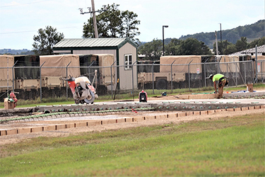
Photos 5 and 6: Reinforcing Doweling Between Roadway Sections (Road Repair Work at Ft McCoy) Source: Scott Sturkol, Ft McCoy PAO
Corrosion effects on PCC include:

Photo 7: Alkali-Silica Reaction on a PCC Bridge Support
Photo Source: D, CPO

Photos 8 and 9: POL Spills and High Heat impacts MV/CV-22 Photo Source: NAVFAC Atlantic
Glass Fiber Reinforced Polymer (GFRP) reinforcement consists of a polymeric material (polyester, vinyl ester, or epoxy) that is reinforced by glass fibers. Advantages of GFRP bars include corrosion resistance, high longitudinal strength, high fatigue endurance, and light weight. Disadvantages of GFRP bars include their high cost, low modulus of elasticity, and low shear strength.
Codes are being developed for non-prestressed GFRP-reinforced concrete used for structural purposes. These codes are not intended for pavements. GFRP-reinforced pavements were successfully used in continuously reinforced concrete pavement sections in Montreal (2006) and West Virginia (2007). However, technical challenges remain for widespread GFRP-reinforced pavements. For example, current GFRP reinforcement does not sufficiently resist transverse shear forces to allow its economic use in pavements—a larger cross-sectional area of GFRP may be required to provide the same shear strength as steel reinforcement. Furthermore, the small volume of steel reinforcement and limited benefit of any weight reduction make a less compelling business case for GFRP use in pavements.
UFC 1-200-01 DoD Building Code, Chapter 4—Corrosion Prevention and Control, provides very specific guidance for design, construction and sustainment actions related to CPC. Tables A-2 and A-2, ESC for DoD Locations, identifies the Environmental Severity Classification (ESC) Zone for each of the DoD Installations around the world, which then drives the selection of the types of materials and processes that should be used for corrosion-prone locations.
The CPC highlights from several of the most relevant UFC and UFGS AC and PCC pavement related criteria include:
UFC 3-250-01 Pavement Design for Roads and Parking Areas provides pavement design procedures and requirements for the pavement design of roads and parking areas worldwide. It clarifies when state pavement design procedures may be used and when Pavement-Transportation Computer Assisted Structural Engineering (PCASE) is required. It addresses both AC and PCC pavement design to include soils, subgrade, base and reinforcing steel. It does not mention UV degradation or corrosion. It does mention alkali-silica reaction, spalling, and steel reinforcement uses and design.
UFC 3-250-03 Standard Practice Manual For Flexible Pavements discusses the importance of pavement maintenance actions, sealers, stabilization, and other useful information concerning mix design, materials, production, and placement of various AC mixtures.
UFC 3-250-04 Standard Practice for Concrete Pavements includes the August 1987 Army TM 5-822-7 and the Air Force AFM 88-6, Chapter 8, discusses the realities of the reaction of steel and de-icing salts and corrosion behavior when water is able to gain access. The use of coated dowels and reinforcing steel should be considered in the presence of seawater. Alkali-silica reactions as shown in Photo 8 are discussed in this UFC, which provides information on their risk, potential damage, and possible solutions. Much has transpired since this UFC was published, including extensive research into heat-resistant mix designs and the categorization and application of ESC Zones (see UFC 1-200-01).
UFC 3-260-01 Airfield and Heliport Planning and Design provides extensive detail on aviation facility design, including clearances. It does not address corrosion directly but contains content associated with vertical landing and takeoff as they relate to heat, surface deterioration and the creation of foreign object damage.
UFC 3-260-02 Pavement Design for Airfields provides an extensive description and discussion related to pavement joints and the associated need to establish and maintain joint integrity. Improper joint design and construction poses a serious risk factor related to CPC of pavements and the aircraft that utilize them. The UFC provides extensive guidance insights into pavement design, and while the word “corrosion” might not be used, the impact of failed subbase, water intrusion, erosion, and PCC cracking allows access to steel reinforcing that causes spalling and foreign object damage (FOD). In sandy soils, where drainage structures are installed under ramps and pavements, the erosion of the subbase into the drainage structure through pipe joints allows the pavements to crack and fail. The UFC also discusses alkali-silica aggregate reaction.
UFC 3-260-16 O&M Manual: Standard Practice For Airfield Pavement Condition Surveys discusses spalling, cracking, and foreign object damage (FOD) identification and severity. Both AC and PCC pavements are addressed and identified in a pictorial presentation. It does not address corrosion factors causing these conditions. The value, from a corrosion perspective, is in the understanding of the causative effects of corrosion on surface, edge and cracking.
UFC 3-270-01 O&M Manual: Asphalt and Concrete Pavement Maintenance and Repair discusses pavement distresses including cracking, rutting, raveling, or other types of surface deterioration which is indicative of the decline in the pavement’s structural load-carrying capacity. Asphalt Concrete (AC) Pavement Distresses are listed. Portland Cement Concrete (PCC) Pavement Distresses addresses the hazards of using gypsum-based PCC (calcium sulfate) repair materials and the presence of free sulfates in the promotion of corrosion in reinforcing steel in pavements. Crack sealing can become a corrosion and FOD problem if not executed properly. UFC 1-200-01 update requires application of new corrosion and related environmental severity guidance and was published after this UFC.
UFGS 03 30 00 Cast-in-Place Concrete covers the requirements for cast-in-place concrete not exposed to a marine or high-chloride environment. It addresses material restrictions to prevent alkali-silica reactions. It has extensive references to corrosion and associated material and admixture selections to prevent reinforcing steel deterioration, increase durability, and corrosion protection. It states requirements to store reinforcing materials to prevent damage that causes excessive rust. It addresses requirements for rust-proof aggregate. It discusses management of rust on reinforcing steel in detail and addresses the various reasons for cracking in the concrete along with associated limitations.
UFGS 03 31 29 Marine Concrete With Service Life Modeling covers requirements for reinforced concrete exposed to marine and chloride environments for projects with a defined service life, ESC classifications C4 and C5, and where deicing salts are used on the structure. Service modeling is described extensively. Corrosion topics are covered in depth on topics to include concrete qualification process and admixtures (corrosion inhibitors). The chloride threshold, corrosion initiation and propagation period, service life and service modeling (placing corrosion in context as a risk factor), and supplemental corrosion protection are addressed. The UFGS requires that deterioration mechanisms other than chloride induced be considered and mitigated. Rust and reinforcing steel are addressed. Cracking and spalling are also included. Note that this UFGS has extensive corrosion management requirements beyond this brief summary.
UFGS 03 31 30 Marine Concrete covers requirements for reinforced concrete exposed to marine and chloride environments for projects with no defined service life design, exposed to weather in ESC classifications C4 and C5, and where deicing salts are used on the structure. Note that UFC 1-200-01 contains the determination of ESC project locations and corrosion requirements. Corrosion topics are covered in depth on topics to include concrete qualification process and admixtures (corrosion inhibitors). Service life and supplemental corrosion protection including inhibitors are defined. Concrete quality control includes corrosion protection strategies, chemical deterioration, chemical inhibitors and supplemental corrosion protection references and requirements. Coatings and inhibitors are described in the context of “supplemental corrosion protection.” Corrosion requirements and reinforcing steel to include prestressing strands, reinforcing bars and supports are delineated. Rust and reinforcing steel are addressed. Shrinkage cracking is also included.
UFGS 32 01 13.63 Gilsonite Modified Asphalt Emulsion Seal Coats covers gilsonite modified asphalt surface coatings for roads, parking areas, airfields and other general applications with or without aggregate applied on the applied coating. The use of Gilsonite modified asphalt sealcoats prevents surface corrosion of asphalt pavements and should be used whenever possible. Sealcoats can be applied post construction and re-applied every three to four years.
UFGS 32 13 13.06 Portland Cement Concrete Pavement For Roads and Site Facilities covers requirements for PCC paving jobs such as roads, streets, sidewalks and parking lots. It mentions corrosion protection from moisture, freeze-thaw cycling and deicing salts. Reinforcing steel should be inspected to ensure that it is free of flaky rust. Shrinkage cracking is also included.
UFGS 32 13 13.43 High Temperature Concrete Paving For Airfields Using Lightweight and Traprock Aggregates is for concrete pavements exposed to temperatures of 482 degrees C (900 degrees F) or higher, referred to herein as High Temperature Concrete. Heat-resistant recommendations exist for concrete exposed to moderate temperatures of 149 to 482 degrees C (300 to 900 degrees Fahrenheit per Engineering Technical Letter (ETL) 14-2 but are also applicable to the specification. There is an extensive discussion about alkali-silica reaction, fly ash, and the associated designs concrete mix designs. Reinforcing steel should be inspected to ensure that it is free of flaky, thin powdery, and tight rust. Steel dowel requirements are addressed along with rust restrictions. Steel forms should be free of rust. Shrinkage cracking restrictions are defined.
UFGS 32 13 14.13 Concrete Paving for Airfields and Other Heavy Duty Pavements covers construction of concrete pavement for Army, Navy and Air Force airfields and heavy-duty roads, parking areas, hardstands, and vehicular traffic. The UFGS addresses alkali-silica reactivity aggregates, combinations of cementitious materials and concrete mix design. Reinforcing steel should be inspected to ensure that it is free of flaky, thin powdery, and tight rust. Steel dowel requirements are addressed along with rust restrictions. Steel forms should be free of rust. Shrinkage cracking restrictions are defined.
The understanding of pavement technology in the context of design, construction, and sustainment, along with the associated risks and stresses, is an absolute must for engineers, architects and sustainment engineers. Saltwater is an excellent electrolyte contributing to an aggressive corrosive environment with the associated impact on facilities. Hydrostatic forces, wind, salt spray, ultraviolet radiation, temperature variations, frost, heave, surface erosion, AC binder failure all contribute to corrosion and erosion of and PCC pavements. Utilizing sustainment management system (SMS) tools such AC as Paver™ , PCASE and Builder, will assist the installation in tracking pavement facilities and identifying maintenance requirements such that they can be quantified, funded, and sustained.
In general, preventive and predictive maintenance is more cost effective than corrective maintenance. Preventative corrosion maintenance can avoid or reduce the occurrence of:
Methods of Corrosion Control for Pavements include:
Figure 1, "CPC Facilities Life Cycle", illustrates the placement of preventive maintenance in the process. UFC 3-270-01 O&M Manual: Asphalt and Concrete Pavement Maintenance and Repair delineates types of maintenance and repair types to include:
Global Preventive Maintenance (PM) (Global PM is used to retard or slow pavement deterioration on a large scale, usually covering more than one section.)
Localized Preventive Maintenance (Localized PM consists of maintenance and repair (M&R) actions performed on individual distresses to slow down the rate of pavement deterioration.)
Operational Maintenance (Also referred to as safety maintenance, stop-gap maintenance, and breakdown maintenance, operational maintenance is performed to mitigate distresses on pavements that are below the critical pavement condition index (PCI) to keep them operationally safe for use.)
The UFC 3-270-01 also provides insights and guidance into the repairs of AC and PCC pavements with the associated chapter details. These sections are excellent starting points as sustainment professionals plan and develop repair programs. It is extremely important to leverage an accurate PM program. There are numerous types of M&R methods for AC and PCC pavements, which include patching, crack sealing, and surface treatments. Keeping an accurate asset database and an associated condition summary facilitates timely M&R actions that will keep the pavement in good operating condition and queued up for timely replacement.
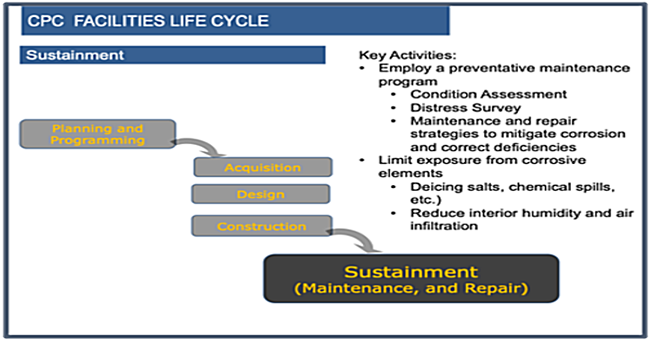
Figure 1: CPC Facilities Life Cycle (Design Service Life) Source: Steve Geusic, P.E.
Figure 2 illustrates the Sustainment process and the associated work flow. Identifying and tracking pavement deficiencies through this process will ensure that the necessary work will be scheduled and accomplished in a timely process.
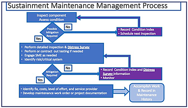
Figure 2: Sustainment Maintenance Management Process Source: Steve Geusic, P.E.
The Ontario Hot Mix Producers Association has developed a good primer on The ABCs of Pavement Preservation with the message that planning understanding pavement management, planning ahead and doing the right thing will result in greater design service life effectiveness for AC pavements. Photos 10 through 14 provide examples of the challenges in the sustainment of pavements.


Photo 10: PCC Pavement Deterioration (55th CES, Travis Drive Repairs) Source: Leticia Cunningham, 55th Wing Public Affairs Office
Photo 11: Harsh Winter Freeze Thaw Effects on PCC Source: Concrete décor

Photos 12 and 13: AC Deterioration, Subgrade Failure, Pumping, Fatigue Cracking, Patching Failure, Loss of Binder and Polishing Source: JCDEAN Indian Oaks Development Photo 14: Potholing, Fatigue Cracking, Weathering and Loss of Aggregate on Surface Treatments UV Deterioration Source: PavemanPro
Through understanding the severity and stresses associated with pavement design, construction, and sustainment, new and existing pavements will have a greater possibility of meeting mission requirements over the design service life. It is essential that the right materials are selected, installed and maintained. Pavements have to hold up to repetitive stresses and forces that can be marginalized by corrosion stressors. The engineer, architect and sustainment professional should seek assistance of subject matter experts (SMEs) in these areas as required to ensure that projects remain durable and sustainable over the desired design service life. The resources provided in this knowledge page are intended to assist in managing issues associated with AC and PCC pavements. Understanding how corrosion impacts AC and PCC pavements will improve designs, construction and sustainment.
Unified Facilities Criteria (UFC)
Unified Facilities Guide Specifications (UFGS)
WBDG Resources
U.S. Army Corps of Engineers
AFCEC—Air Force
Navy—NAVFAC
Tri-Service Electrical Working Group (TSEWG) and Pavements/Airfields Working Group (TSPWG)
Tools
Training
DoD Installations Organizations
Federal Aviation Administration
Federal Highway Administration
Reliability is a great concern for building occupants and organizations. Absence of reliability directly affects personal security and well-being, as well as mission critical work. As workplaces evolve in response to changes in organizational structure and work practices, reliability needs to take into consideration the multiplicity of spaces that support individual and group activities. This applies to all facilities whether public or private, institutional or commercial, large or small, regardless of location, circumstance, and/or purpose. Organizations and the occupants of their buildings are entitled to work places that enable them to remain productive and in-touch at all times. Further, there are financial implications of time lost when systems fail and the workspace is not conducive to occupant productivity. Down time does adversely affect the bottom line.
People increasingly expect work settings to fully support pursuit of individual, team, and organizational objectives without operational uncertainty. Building and information systems that disrupt workflow will not be tolerated. The workforce of the future will demand workspace and tools that amplify their abilities and help them do their best to compete effectively. This calls for systems that perform reliably with good maintenance support.
Building users must be able to rely on facility hardware and software for health, life, safety, power, data, and voice delivery systems (and related equipment and tools). These systems need to function consistently and be properly maintained. When the workplace is supported by high-performance systems that require appropriate levels of maintenance to minimize downtime and have back-up capabilities to ensure negligible loss of service, worker productivity can be improved or maintained.

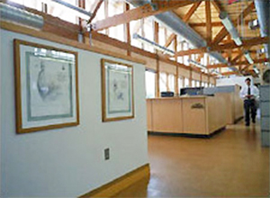
Workers at the Philip Merrill Environmental Center in Annapolis, Maryland, enjoy access to daylight and views from all areas of the building.

The roof-top photovoltaic array at The Bullitt Center in Seattle, Washington supports the Net-Zero goals of the project. Photo courtesy of Benjamin Benschneider

Card key system
Increasing demands for renewable, energy-efficient, and environmentally responsible back-up power sources have lead to advancements in fuel cell technology, solar, wind, hydro, and biomass power systems.
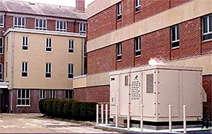
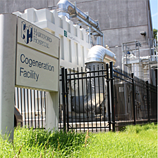
Fuel cell power plant installation at South County Hospital, Wakefield, RI Photo Credit: ClearEdge Power
1.4MW Fuel Cell Power Plant at Hartford Hospital, Hartford, CT Photo Credit: Fuel Cell Energy
Enterprise Resource Planning (ERP)—the integration of all departments and functions across an agency/company onto a single computer system that can serve all those different departments' particular needs.
Reliability-Centered Maintenance (RCM)—the concept of developing a maintenance scheme based on the reliability of the various components of the system or product in question. Implementing a preventative maintenance program using RCM can greatly reduce the cost of ownership of a product or system.
For most building owners and operators, reliability ranks almost as high as cost as a top "quality indicator" when selecting building systems and equipment. "Problem prone equipment," often selected due to lower first costs, reduces system reliability and is clearly a chief motivator for purchasing quality equipment.
Continuous Commissioning—an ongoing process to resolve operating problems, improve comfort, optimize energy use, and identify retrofits for existing buildings and central plant facilities. Continuous commissioning ensures that the building and systems operate optimally to meet the current requirements, which supports worker effectiveness.
(a'treem), term for an interior court in Roman domestic architecture and also a type of entrance court in early Christian churches. Today atrium means an enclosed multi-storied space that is open vertically to multiple stories.
NFPA 92B the current standard for smoke control in large spaces defines atrium as a large volume space created by a floor opening or series of floor openings connecting two or more stories that is covered at the top of the series of openings and is used for purposes other than an enclosed stairway; or other mechanical and utility service to the building. The International Building Code (IBC) defines Atrium similarly as an opening connecting two or more stories other than enclosed stairways, elevators, hoist ways, escalators, plumbing, electrical, air-conditioning or other equipment, which is closed at the top and not defined as a mall.
Atriums have many advantages as a building form over conventional modern building configurations. Atrium buildings appeal to people not only logically, but also emotionally by providing a connection to the outside inside. By bringing natural light into the interior, atriums offer larger, more efficient floor areas than conventional buildings. Atriums provide more desirable work environments by providing more space with a connection to natural daylight and the outside environment. Many believe that access to natural full spectrum lighting creates a more healthful and productive environment. There have been several studies that support this view.
The view into an atrium can and in most cases is more entertaining and connective than an exterior view as illustrated below at The Plaza of the Americas in Dallas, Texas.
An atrium is a pleasant all weather gathering place providing shelter from the more extreme climate conditions outside. The atrium replicates a desirable outdoor environment by providing the benevolent aspects of the outdoor environment; natural light, moderate temperatures while sheltering us from the harsher elements of extreme temperatures, rain, and winds.
Because atriums are so complex, they create unique interrelationships between fundamental elements that must be understood and accounted for in the final design. Atriums will contain many compromises; the designer must understand the negatives as well as the positives of each component in the relationship to the complete atrium environment. Many atriums have been built where unintended consequences have compromised the design.
The complexity of atrium design does not lend itself to prescriptive standards, but sound life safety principles must be incorporated into every atrium design. Good atrium design will maximize the natural environment to minimize energy consumption.
Atriums can be configured in an infinite number of ways, but atrium configurations should be always a reasoned response to the climatic and life safety goals. Typical atrium configurations can be totally surrounded by building elements or partially enclosed. They maybe top lit, side lit or a combination of both. The configuration of the atrium will dictate many of the fundamentals of atrium the components. The first consideration of atrium design is an acknowledgement of the necessity of fire and smoke management. Building configuration is the most significant factor in smoke management and thus must be fundamental to the design.
The details associated with this section of the BEDG on the WBDG were developed by committee and are intended solely as a means to illustrate general design and construction concepts only. Appropriate use and application of the concepts illustrated in these details will vary based on performance considerations and environmental conditions unique to each project and, therefore, do not represent the final opinion or recommendation of the author of each section or the committee members responsible for the development of the WBDG.
The shape and geometry of an atrium is both the product of and the reason for the adjoining occupied portions of the building. Inhabited by office workers, residents, or other uses, these spaces are impacted greatly by the configuration of the atrium space. The configurations can refer to the shape in two or three dimensions, the scale or the layout of the surrounding spaces and how they are connected to the atrium.
There are several simple and several complex basic configurations of atrium space. They are:
1. Single sided: Atrium abuts one side of the occupied portion of the structure.
2. Two sided: Atrium abuts two sides of the occupied portion of the structure.
3. Three sided: Atrium abuts three sides of the occupied portion of the structure.
4. Four sided: Atrium abuts four sides of the occupied portion of the structure.
5. Linear: Atrium sandwiched between two occupied portions of structure.
1. Bridging: Atrium connects several occupied portions of structure.
2. Podium: Atrium sits at the bottom or below an occupied portion of structure.
3. Multiple Lateral: Atrium spaces scattered throughout plan on single or multiple stories.
4. Multiple Vertical: Atrium spaces scattered throughout height of tower structure.
These different configurations can be developed to myriad architectural statements but the basic configurations remain recognizable. Which configuration is utilized by an individual designer is a function of (among other issues) personal taste, life safety issues, proposed uses of both the atrium and adjoining spaces, impact the atrium is wished to have climactically, geographic location, urban context, and scale of the atrium desired.
In the last couple of decades there has been dozens of scholarly papers and research studies on all aspects of indoor environment quality and its relationship to worker productivity and well being. In the United States, the oft-cited "West Bend" study by Walter Kroner and colleagues at Rensselaer Polytechnic Institute documented productivity gains from daylighting, access to windows, and a view of a pleasant outdoor landscape at the West Bend (Wis.) Mutual Insurance Company. According to the study, productivity gains in the new building increased by 16%, with the personal controls alone accounting for a 3% gain.(x)
Another frequently cited report is the Heschong Mahone Group study "Daylighting in schools," which was conducted on behalf of the California Board for Energy Efficiency. The researchers analyzed test scores for 21,000 students in 2,000 classrooms in Seattle; Orange County, Calif.; and Fort Collins, Colo. In Orange County, students with the most daylighting in their classrooms progressed 20% faster on math tests and 26% faster on reading tests in one year than those with the least daylighting.(x)
Natural light as it pertains to atriums is a basic element of the design. The light within the atrium as well as the light transmitted to the adjoining occupied space needs to be considered. The light coming into the atrium is impacted by several factors:
The average brightness of the local sky is a factor. This will affect the amount and type of glazing used for the exterior skin. Sufficient openings should be provided for the amount of light expected at the bottom of the atrium space. Additionally, the type of glazing, whether transparent or translucent will impact the amount and quality of natural light admitted to the atrium. Below is an example of natural light from a sky lit atrium at EDS Corporate Headquarters in Plano, Texas where significant daylight was desired at the floor level.
The orientation of the glazing will have significant effect and needs to be a fundamental consideration. Glazing facing to the east or west should be avoided as it is difficult to control glare because direct sun at low angles will be admitted at some point during the day. Horizontal glazing at the roof should also be carefully considered because direct light is inevitable from this orientation. Diffuse natural light generally is the preferred form of natural lighting.
Reflectivity of wall surfaces facing the atrium should be a consideration. Bright surfaces will reflect light and maintain light levels deeper down into the atrium space and therefore transmit this light to the adjacent occupied spaces.
These issues must be balanced to provide an adequate amount of light at the occupied areas of the atrium as well as the quality of light desired for the proposed uses. Also a consideration is the amount and quality of light available to the spaces adjacent to the atrium. At the top of the atrium abundant light will be available and therefore it may be desirable to provide smaller openings to admit this light while providing more reflective surfaces in order to allow the light to penetrate deeper towards the floor of the atrium. Larger openings provided closer to the floor will admit a higher level of light, the deeper the atrium the more glazing will be necessary. To aid light in penetrating the adjacent spaces more evenly and deeper, light shelves can be utilized at each level facing the atrium. This strategy may require higher floor to floor dimension to operate sufficiently but will also reduce the need for general artificial light on each floor within a reasonable dimension of the atrium. In warmer climates, this reduction in artificial light may also improve the occupied space's thermal performance and reduce cooling loads.
The light allowed into the atrium can be varied or controlled by external or internal shading devices. These can be configured in a number of ways, vertically, horizontally or at angles to accomplish the desired shading as well as act as a design element. The need for shading devices depends on the strength of light reaching the atrium skin and this depends on the location geographically. External shading devices are used to prohibit light from directly entering the atrium and therefore controlling the heat gain associated with direct light. Internal shading lets the heat in but prohibits direct light from getting down to the usable space of the atrium.
Resistance to the elements is the primary focus of the atrium enclosure. Several components can make up the skin of the atrium. They are the walls, roof and any sloping surfaces that act to keep water and wind out of the interior space and control the amount and quality of daylight penetrating the space. (Refer to Wall Systems)
In order to accomplish these goals, openings in the atrium skin should be limited to those required for ventilation and smoke evacuation at the top and bottom and pedestrian access or exit at the bottom. The Pedestrian access or exit should be accomplished through revolving doors or power sliders or swing doors in a vestibule configuration. This will help control drafts in the atrium induced by the stack effect in these large spaces. The enclosure elements of the atrium have to react to the structural building frame as well. This is accomplished through the use of movement joints to resolve a variety of differential movement between the skin and the frame, different skin elements as well as different building elements. These joints should be tracked horizontally, vertically and diagonally to termination and detailed to maintain weather tightness along their entire length and at termination or transition points. Below are some simple details showing the tracking of an expansion joint through different conditions and materials.
Plan Details at Expansion Joint tracking through different materials.
Plan Details showing tracking of expansion joint through different skin materials.
Exterior glazing systems used in atrium enclosures should be of a high performance curtain wall system designed and constructed expressly for the purpose of spanning large distances while controlling water and air infiltration without the aid of water shedding overhangs or other protection. The interface of these systems with adjacent material and systems should be detailed carefully taking into account different movement and movement characteristics. One type of movement that can occur is due to thermal expansion and contraction of building materials. Different materials can experience large differential movements over the same temperature change. Slip connections can typically be utilized within building systems to account for this differential movement. Deflection is another type of movement that should be considered. Deflection joints can occur at every floor level or every other floor level depending on vertical spans and loads being carried. Different structural support conditions can also telegraph through the exterior skin as expansion or construction joints. Attention must also be paid to geographic location, wind loading on components and cladding which will vary. Some coastal regions will require the consideration for large and small missile impact zones on the exterior skin and this will further increase the required performance characteristics for the system. Below is a view of the inside of such a curtain wall system and the structural back up required to support it.
Roofing systems for atria can also pose severe challenges due to the desire to admit light through the roof using skylights or a translucent roof system. The roofing system should be designed to accommodate the expected volumes of water and/or snow by removing these from the roof in an adequately short period of time as well as supporting them structurally while this is accomplished. (Refer to Low and Steep Slope Roofing Assemblies)
Sloping skin elements provide a separate set of concerns. While neither wall nor roof, they take on characteristics of both. They must perform to maintain a weather tight seal, accommodate movement in multiple directions and tie into adjacent systems at difficult angles. Further, the prospect of providing exterior building maintenance (E.B.M.) systems on sloped surfaces is difficult, and additionally so if the slope is reversed to extend out while moving away from the floor. Support for staging rigs used to provide cleaning, maintenance, repair or glass replacement should be provided to keep the stage away from the glazing system as well as safely anchoring it to maintain lateral stability as the rig moves up or down the vertical of sloping surfaces. Vertical or sloping atrium faces have additional challenges as the interior surfaces requiring access may not be sufficiently close to a floor surface in order for maintenance to occur. Therefore an interior building maintenance system should be considered to operate similar to the E.B.M. system. These interior systems can be at least as complicated as the exterior systems and often times more so due to the design intent that they not be visibly heavy or obvious inside the atrium while offering the same level of access to the portions of the building skin as the exterior systems as witnessed below at 311 South Wacker Drive in Chicago, Illinois.
Glazing in a horizontal application requires protecting atrium occupants from falling glass either by utilizing wired glazing, laminated glazing or providing safety screening below the glazing.
There are three basic components to the landscaping or softscape of the atrium. The planting medium, the plants themselves and the space above the planting all contribute to the success of the planting.
Planting while the primary focus can be extremely difficult to predict what types will live thrive and survive in an atrium space. A qualified landscape consultant should be retained during design to select planting and oversee the project through installation and beyond. There are some basic guidelines to plant selection. Sub tropicals should be used as they can handle the fairly consistent climate within a building.
The planting medium also has significant impact on the overall effect. Starting with planter sizes that are appropriate for the selected plants, proper soil mixes, drainage/ irrigation characteristics and nutrients that will be necessarily introduces to the planting areas following installation. These issues also should be left to the landscape consultant to determine and incorporated into the design by the building designer. Of these adequate drainage and water supply should be planned on by the designer from the start.
Once these issues are established, the design of the volume of space above and around the planting is where the designer can have the most influence. Plants derive their beauty from the energy they can absorb from their environment. Light, temperature, and humidity all contribute to the growth potential of the interior planting. The amount (both intensity and duration) and quality of light provided are factors to be considered. Light in the crown of the sky will be of higher intensity than at the horizon and therefore roof lit atria will provide higher light intensities than side lit ones. This light direction will also impact the growth patterns of the interior plants and therefore should be considered. If the light in the atrium is not of sufficient brightness to support the plants proposed, artificial light can be introduced. This light should be of the proper type, that is have acceptable color rendition and be of the right frequencies to promote plant growth. Typically it is not necessary to employ horticultural type lighting due to poor color rendition and little improvement in plant performance. The light range within the atrium should be maintained between 700 and 1,000 lux with a bare minimum of 500 lux for a duration of 12 hours per day(1). This light level can be achieved with daylight solely, and combination of daylight and artificial light or in extreme situations, solely artificial light. In any case, infra-red and ultraviolet light frequencies are detrimental to plant growth and should be filtered from the natural light if possible or not produced with artificial lighting. Artificial light should be turned off or reduced to minimum acceptable levels to provide safe pedestrian travel at night as the plants need to maintain good diurnal variation or distinguishable night/ day cycles.
Temperature also plays a large role in the landscape's success. Planting should be held back from sources of cold air such as unprotected entries (those without a vestibule or revolving door) cold spots due to uninsulated glazing, mechanical air distribution locations. Planting needs to experience some temperature variation during the day and night again to maintain the proper diurnal variation. A range of 70-75 degrees F is good during the day with a range of 60-65 degrees F at night. A minimum temperature of 50 degrees F should be maintained at all times unless plants have been chosen specifically to exist at lower temperatures.
The humidity in the atrium is also at issue. Plants will naturally increase the humidity in an interior space. Mechanical systems typically will counteract this phenomenon however and maintaining a high humidity inside may not be possible. This is not a large problem as most plants will be able to exist in this environment without much difficulty but its effect must be understood because it might be of consequence. The entire life cycle of the planting should be incorporated into the understanding of the plants role in the atrium. Plants that require extra maintenance to be appropriate to their atrium environment should be understood and incorporated into the Atrium planning. An example might be ficus types that drop an inordinate mount of leaves and thus require excessive maintenance.
There are many impacts on the acoustical performance of an atrium space. The designer needs to decide early on the uses and types of activities to be supported both within the spaces and in adjacent occupied areas. These can range from gatherings for various events, musical performances and dances, lobby and reception function, or simply transitory from one part of the building to the other.
The basic functions of the atrium space and adjacent occupied areas will greatly impact any acoustical systems being considered. First, within the atrium space, what is the acceptable ambient noise level at the floor and in what range can the noise level be expected based on the design being considered. Medium to low thresholds of noise from the HVAC system at the floor will require consideration at the design stage. If the Atrium configuration has a dome and/or other round focusing surfaces, then the materials such as reflective and acoustical absorbing must be carefully considered. Secondly, the range of functions must be considered. Range of functions could be for instance musical concerts, parties and receptions, sit down dinners where individuals are sitting and having a conversation with those in close proximity. The musical performances want to have slightly higher reverberation to support the music, but the others want to have lower reverb for better speech privacy and ease of conversation. An example of a place that needs to be designed for both music and speech would be a church, the design has to strike a balance to serve both functions.
Acoustical parameters such as reverberation time and speech intelligibility must be considered for these functions. For example, if gatherings for corporate events or receptions are important functions then the reverberation time should be lower so the speech intelligibility will be reasonable. When the speech intelligibility is poor it is difficult to hear a conversation clearly. This is commonly known as the "Cocktail Party Effect." It may be necessary to have the acoustical criteria set for a variety of functions, but if there is a lobby and reception function then localized absorption is desirable for a clear conversation between the visitor and receptionist.
Atria typically involve large open spaces connecting multiple floors. In some instances the space can be large enough that individual zones of greatly varying temperatures may exist within the atria. These zones may develop air currents within the atrium that may be stronger influences than the HVAC system. If the space is large enough, it is possible to create ‘rain’ indoors.
When only one wall of the atrium is an outside wall, it is possible in the warmer seasons for the air next to the wall that absorbs the walls transmitted heat to rise. Depending on the height of the space, air currents could develop and become a strong enough force overpowering the influence the diffuser placement has over the air movement. With multiple walls, the problem can still occur but tends to be less substantial due to more uniform temperature profiles.
Air currents due to load concentration may rise and displace the stratified air at the top, forcing the warmer air down. When cooling loads assume that stratification will occur, the design should not include heavy localized loads or unbalanced exposures. Architectural configurations of atria that include these requirements are rare. Therefore it is recommended that cooling loads do not assume stratification unless it can be reasonably shown that strong thermal currents will exist in the particular design. The design concept of spot cooling only the occupied areas is acceptable, but high diffuser throw velocity must be maintained to counteract any thermal induced air currents.
Under heating conditions, if the atrium is topped with a skylight or poorly insulated roof, warm moist air from the occupant level may rise and be cooled by the top exposure. This could create condensation.. This situation should be avoided, since it can potentially damage the structural components of the roof assembly. (Reference ASHRAE 1999 Applications, Chapter 4.8.)
Atria, unlike most designs in HVAC, should be viewed as a three dimensional volume from the start of the project. Normal engineering practices such as CFM per square foot, or square feet per ton usually do not apply to an atrium. The engineer should use sketches, sections, models, and plans to understand the space from three dimensions from the very start by working with the architectural team at the planning stages. It is key that the engineer understands all aspects of the atrium volume due to the impact on airflow movement and pressurization.
The smoke control system requirements for an atrium in many cases will dictate the HVAC design instead of the cooling or heating of the space. The smoke management system design should be well developed prior to designing the thermal comfort system. Once the smoke management intakes, fans, ducts, and diffusers are generally established based on the smoke management requirements, the potential to use these for thermal comfort can be considered. Again, it is key that the thermal comfort air system and smoke control system be implemented into the architectural design at the building planning stage. The smoke management system should not be compromised to take advantage of a designed thermal comfort system. The two systems must be designed in concert. The thermal air currents and any stratification during a fire event are completely different than in normal operation. This section only applies to the atrium thermal environment during normal operation. Refer to the Smoke Control section for the life safety design of the atrium. (Reference ASHRAE 1999 Applications, Chapter 51.)
The intended use of the atrium has an effect on the HVAC design and must be established early on in the design process. Is it a transient space only such as a hallway, or will seating be provided for people to lounge and interact? Will there be large gatherings of people during special events? What type of finishes and furnishings will be placed in the space? Will there be seasonal decorations such as a Christmas tree that will increase the fuel loading used for smoke control calculations? (Reference ASHRAE 1999 Applications, Chapter 51.13)
The use of the atrium may vary from the building it serves, atriums tend to be universal spaces used for many functions. Atriums are often used for large gatherings and functions. The anticipated occupant load the system is designed for should be documented and provided to building management. If the outside air ventilation system or the space thermal comfort system was not designed to accommodate dense occupant loads, the building management should understand the limitation on the use of the atrium.
If the space will be a transient space only, the design temperature range can be expanded. If seating, dining, or other uses where occupants will remain in the area for an extended time are intended then design temperatures should remain more stringent, similar to other spaces of similar use.
The following items should be considered:
Since an atrium by definition communicates or is adjacent to many different areas of the building, the pressure relationship between the atrium and other spaces is crucial to a successful design. In many cases, the atrium is also the main entrance to a building and the pressure relationship between the atrium and the outside is critical to the control of overall building pressurization.
The conditioning and ventilation of the atrium usually involves large quantities of air, so the infiltration or ex-filtration is an even smaller percentage of the total quantity of air being handled. This may require controls and instrumentation to be of a higher quality and accuracy than is typical in the remainder of the building. It also makes the initial, and ongoing, balancing of the atrium systems more critical to the overall success of the project. This must also work in concert with the smoke control pressure relationships. (Reference ASHRAE 1999 Applications, Chapter 51.12)
Stack effect and thermal currents may produce unanticipated influences on pressure relationships if not accounted for in the design. Therefore the atrium systems should be designed to allow some flexibility at start-up and in the future to adjust the balancing of the systems. This may include upsizing the atrium equipment to a condition greater than calculated for outside air or relief/exhaust quantities. This same thermal stratification has significant impact on the smoke control system operation in its ability to properly draw smoke and maintain pressure relationships. (Reference ASHRAE 1999 Applications, Chapter 51.13)
Since atriums are usually the focal point of the building and communicate with most all other spaces, atrium pressure should be considered as the datum that all other spaces are compared to. If the atrium is maintaining a slightly positive pressure relative to the outside, than most spaces should be designed to be neutral to the atrium and match the atrium pressure thus maintaining a positive building pressure. If too many spaces are designed positive to the atrium, the combined infiltration of air into the atrium may exceed its relief capabilities and over pressurize the building causing excessive air movement at building entrances. Due to seasonal thermal effects, the system should utilize automatic controls that will adjust the balance of the atrium based on outside temperatures or atrium pressures.
The most critical of all the technical issues to be solved in a successful atrium design is Life Safety because atrium buildings break with orthodox concepts of Safety. Life Safety design for any building is difficult. It involves more than a provision for emergency egress, it requires attention to who will be using the building and what they will be doing. Consideration must be given to communication, the protection of escape routes, and temporary areas of refuge allowing reasonable time for the building occupants to reach safety.
Because of its critical nature both NFPA 101 "The Life Safety Code" and The International Building Code have extensive code provisions for Atriums. Since the code provisions are extensive we will not recite them here but refer any design team to an exhaustive review of the requirements. Both NFPA and the IBC give significant explanatory material to atriums in their Life Safety Code Handbook and IBC commentary respectively. While similar they are not identical. A significant difference is that the IBC is prescriptive and arbitrarily limits the number of floors that maybe open to the atrium to three, where the Life Safety Code is more performance oriented and will allow the number of floors open to the atriums without enclosure be based upon the results of the required engineering analysis.
One of the basic premises of atrium requirements is that an engineered smoke control system combined with an automatic fire sprinkler system that is properly supervised provide an adequate alternative to the fire resistance rating of a shaft enclosure. It is also recognized that some form of boundary is required to assist the smoke control system in containing smoke to just the atrium area.
Both the Life Safety Code and IBC require that the atrium space be separated from adjacent areas by fire barriers having a fire rating of 1 hour or equivalent. Both codes accept adjacent spaces to be separated by properly constructed glass walls where automatic sprinklers have been installed to protect the glass. The sprinklers are to be located so as to wet the entire surface of the glass.
The development of most code provisions has largely been a response to specific fires and the desire to prevent recurrences. For example, in recent times many present code provisions were responses to the Coconut Grove Night Club fire, the Chicago school fire, and the MGM Grand fire. Conventional doctrine dictates that to achieve Fire and Life Safety that fires must be kept as small as possible and the effect of fire limited to as small an area as possible. This philosophy has resulted in conventional building configurations employing compartmentalized construction of fire rated floors and fire rated walls.
While atrium design breaks with conventional building configurations Fire / Life Safety in atrium buildings is comprised of the same three elements as in conventional buildings—means of escape, smoke control, and fire control. Means of escape, emergency egress is a fundamental plan issue and must be integral with the circulation concept of the building. Emergency egress must be incorporated from day one. Smoke control strategies are also fundamental and must be part of the initial ventilation concepts. Fire control and fire fighting provisions must also be integrated in to the original concepts.
The basic concept of means of egress planning is that occupants can move away from a fire and reach a protected means of egress by their own unaided efforts. This route must remain tenable throughout the evacuation process. A complicating element that must be addressed is that in an emergency people tend to use the route they are familiar with. Occupants of office buildings can be trained by fire drills but visitors will only know the way they came in. Means of egress protected exit stairs should be on familiar routes and in intuitive locations and signed very clearly. Mean of egress should not be unduly exposed to potential hazards. (Refer NFPA 101) The Life Safety Code being more performance based requires that an engineering analysis be performed to demonstrate that smoke will be managed for the time needed to evacuate the building. To accomplish this, the analysis must prove that the smoke layer interface will be maintained above the highest unprotected opening to adjacent spaces, or 72" above the highest floor level of exit access open to the atrium for a time equal to 1.5 times the calculated egress time or 20 minutes, whichever is greater. For a protect-in-place occupancy, such as Healthcare, the evacuation time is considered to be infinite, which means that the smoke control performance criteria must be maintained indefinitely.
The fire record has shown that smoke is the primary threat to life from fire in buildings. Smoke is the most rapidly developed threat. Proper smoke control in an atrium building is an absolute must. Smoke control systems that are integral to the buildings ventilation systems are preferred over stand alone systems. Integral systems are more reliable because their components are constantly being monitored and maintained. (Refer NFPA 92B Guide for Smoke Management Systems in Malls, Atria, and large areas.) NFPA 92B, quantifies the physics associated with atrium smoke control and presents methodologies for system design in an understandable and useful format. The guidelines of NFPA 92B allow the system designer to design a system and prepare associated documentation to access for adequacy in meeting the performance criteria.
The basic nature of fire and smoke must be well understood by the design team in order to incorporate smoke control in to the physical configuration of the atrium from the earliest schematic designs. Well designed smoke control cannot be added to a design, it must be integral to the design.
Effective smoke control depends upon rapid control of fire size to limit smoke quantities to manageable volumes. Fundamental to effective smoke / fire control is early detection and suppression. Smoke and or fire detection systems must be designed to identify and locate a fire early in its development. The fire prevention and smoke removal strategies for the atrium will vary dependent on the location of the fire and the configuration of the atrium.
Large volumes and high ceilings significantly complicate and possibly delay early smoke and heat detection. Systems that can detect the smoke near the occupied floor levels and close to the potential fire sources are best. Smoke detectors should be placed in ceilings in spaces surrounding the atrium but located within the atrium enclosure. These include balconies, seating alcoves, corridors, lobbies, and other spaces that have typical ceiling heights. To detect smoke in the high ceiling area, detectors should be located near the atrium floor to detect smoke prior to rising and potentially dissipating in the large volume. If the space is tall enough, smoke will cool and begin to descend back to the floor level, without reaching the upper ceiling level. Beam detectors are one potential solution to detecting smoke at lower levels of the atrium. If used, the location of beam detectors transmitters and receivers must be carefully chosen to allow the proper coverage, and to allow easy access for adjustment, testing, and periodic maintenance. Smoke and or heat detectors should also always be placed at the highest ceiling level as a precaution in case the other detection systems did not activate. The figure below in a highly simplified form represents many of the items that must be considered in the smoke control system in an atrium.
Example of an atria air flow.
Early suppression of a fire is essential to effectively limit the amount of smoke to manageable levels. Automatic sprinklers are the most effective means of fire suppression appropriate to atriums. The fundamental nature of atria presents challenges to the effective use of automatic sprinklers. In atriums with high ceiling heights, typical sprinkler designs provide marginal fire extinguishing capabilities and may actually be detrimental to the smoke removal system. Water from sprinkler heads located greater than 75 feet above the fire source may break up into a fine mist and evaporate before reaching the fire source. The evaporation of sprinkler water may cool the smoke and reduce the effectiveness of smoke removal systems, which were designed to pull the smoke from the top of the enclosure.
A qualified life safety consultant or fire protection engineer (FPE) involved early in the atrium design is the best source of potential fire detection and prevention system selection options. The FPE is knowledgeable in all of the atrium code issues. The codes and standards that address smoke control systems for atria are based on similar research and fundamental fire size and smoke generation models. ASHRAE 1999 Applications, Chapter 51 provides a broad design basis for smoke management that provides general directions to the designer. NFPA 92 is more specific and provides a set of calculations that can be performed by the FPE to determine the quantity of exhaust necessary to evacuate the smoke generated by the largest anticipated fire size. The calculations cannot anticipate all of the aspects that are unique to the atrium under design, and therefore should only be used for the most simple of atrium configurations. For all atria, and especially complex or tall atria, a qualified life safety consultant should be employed to assist in determining the smoke control system parameters. Currently the most comprehensive method of determining complex smoke management criteria is with computer fire modeling. (Reference ASHRAE 1999 Applications, Chapter 51.12) In many instances the results of the computer modeling will result in lower exhaust quantities being required, and therefore lowering initial project costs. The model allows multiple fire origins to be evaluated, and the resulting smoke removal system needs to be adequate for all anticipated fire origin location.
Computer modeling and visualization are important tools for understanding the processes of fire behavior. Fire models range in complexity from simple correlations for predicting quantities such as flame heights or flow velocities to moderately complex zone fire models for predicting time-dependent smoke layer temperatures and heights. Zone fire models' calculations can run on today's computers within minutes because they solve only four differential equations per room. Zone models approximate the entire upper layer with just one temperature. This approximation works remarkably well but breaks down for complicated flows or geometries. For such cases, computational fluid dynamics (CFD) techniques are required.
Even when the actual exhaust quantities were determined by use of a computer fire model, smoke management systems shall be designed in adherence to all other requirements of NFPA 92. Requirements such as the use of direct drive equipment in lieu of belt drive, protection of control wiring, emergency power, and the design and installation of a fireman's control panel to allow manual operation of the smoke removal equipment is mandatory. (Reference NFPA 92)
The operation of the atrium can be diverse and requires close coordination between the designer and user to determine what aspects of the operation that are key. Some of the more critical elements are occupant comfort thru the air system, the mode of operation for the atrium and lighting considerations.
The key elements that the design engineer should consider in the atrium comfort system design are space temperature, energy efficiency and air system type. (Reference ASHRAE 1999 Applications, Chapter 4.8) These are described below.
Space Temperatures—The design temperature for the atrium can vary dramatically based on usage. If the space is to be a heavily occupied, constant use space, 75°F should be considered (summer design). However, if the space is a transient operation, a higher temperature of 78°F should be considered.
Energy Efficiency—Energy efficiency should be considered in the design such as these listed below.
None of these energy efficiency means however should compromise neither the airflow requirements nor the fire protection or smoke control design aspects discussed in other sections.
System Type—While variable air volume systems are recognized for their energy saving ability, they should be carefully scrutinized in the design process for their ability to maintain proper atrium pressure control. Typically, large vestibules are utilized at the atrium entry. Consider using a constant volume air supply in the vestibule to overcome wind pressure at the entry point.
It is important that the designer works closely with the building user in the planning stages to determine the many modes of operation that are anticipated .The building user will set the modes of operation. Thru a firm understanding of the modes of operation desired, the designer can provide as much flexibility in the building control system to achieve a detailed level of control for HVAC zone control, temperature reset, lighting functions, etc.
The lighting of an atrium can be a significant challenge and the use of a specialized lighting designer should be considered. Atrium lighting schemes must be evaluated on an individual basis according to the function of the space and nighttime operation. The following should be considered:
The following are examples of atria that exhibit the above concepts in different combinations, locations and architectural styles. Hopefully they will help explain the concepts and give them physical representations.
The Plaza of the Americas in Dallas, Texas is an example of the bridging atrium, a complex form which utilizes the atrium to connect several buildings. In this case two twenty five story office towers, a twelve story hotel and a twelve story parking garage. There are retail shops at the two lowest levels, one below grade around an ice skating rink. Natural light is admitted to the atrium space through full height glazing at the side walls between the buildings being connected as well as through narrow skylights running across the roof in an angular fashion. Additionally, prisms are suspended inside the side wall glazing that produce interesting color patterns on the interior atrium surfaces. The light entering the atrium is transmitted to the adjacent buildings through floor to ceiling clear glass. The exterior atrium and building glass is heavily tinted and has a 30" high spandrel sill limiting vision glass area to limit the amount of heat gain. The Atrium is oriented with its long axis north-south. The atrium space is climatically tempered as opposed to controlled. This saves energy costs for the attached buildings while limiting the expenditure for both capital and operational for HVAC equipment for the atrium.
The smoke control is achieved through smoke vents at the bottom and top of the atrium exterior walls activated through smoke detectors. This passive smoke control design produced in the late 1970's is not the recommended method of smoke control based on today's codes or standard of care.
The exterior skin is a glazed curtain wall system supported by steel wide flange beams spanning between the building structures which the atrium connects. The roof system consists of deep long span steel trusses covered with exposed metal deck, insulation and roofing. While functional, this roofing system might seem a little light for the volume of space enclosed. Exterior building maintenance is achieved with traditional davits, tiebacks and stages at the exterior while botsains chairs rigged from the roof trusses accessed through a catwalk system. Stages could be rigged from the trusses also if required.
There is one bank of glass elevators exposed in the atrium which serve the parking garage which allow all tenants and visitors to enter the complex in a grand way seeing the whole atrium and building complex upon arrival. Each building also has an individual entrance accessible without entering the atrium. The lower portion of the atrium can be accessed from grade and has wide sidewalk like pathways adjacent to all buildings and overlooking the ice skating rink at the below grade level. Connection between the two levels is via two sets of escalators, the glass elevators or several sets of stairs.
Landscaping within the atrium is limited with small planting areas utilizing potted plants surrounded with mulch to give appearance of continuous planters. Additionally there are large palm trees in individual planters recessed into the lower level floor which are water proofed, drained and irrigated. This planting scheme minimizes the maintenance required for completely irrigated and drained planters while maximizing the effect of the landscaping provided.
This atrium application is also connected to adjoining properties via a sky bridge system which provides a link to a system of climate controlled accessways to other downtown buildings during the hot Texas summers. This atrium also provides a food court which is utilized by tenants as well as visitors from other area buildings. This provides economic help through leasing atrium space as well as producing income for tenants.


The Bayfront Medical Plaza is an example of a two sided atrium, a simple form which sits in the corner between two wings of a medical office building. The building is five stories with a two story space connecting the wings and the atrium on the face. The atrium is five stories high with full height glass on the exterior faces and punched opening between it and the building. It also connected to the adjacent parking garage via a sky bridge. The atrium is completely climate controlled with accessible floor space at the Ground Level and Level 2.
The Life Safety systems have a smoke evacuation system consisting of a coffered ceiling with vents and mechanical units for the venting of smoke. This system is activated by smoke detectors or sprinkler line flow switches. The building and atrium are fully sprinklered as well as the glass separating the building from the atrium in the punched openings.
The exterior skin of the atrium is a glass curtain wall system with tinted insulated glass in aluminum frames supported by a steel structural frame which is clad with GRG (glass fiber reinforced gypsum) panels and gypsum board furring. The roof is composed of steel wide flange beams covered with metal deck, insulation and roofing system. A suspended gypsum board soffit system creates the coffered ceiling which allows for mechanical systems and lighting to be placed aesthetically. Exterior building maintenance is achieved with davits and tie backs and stages while interior building maintenance is achieved through supports off of the steel structure.
Vertical transportation is independent of the atrium. The atrium acts as entry point for the building as well as collecting visitors from the parking garage across the street from the sky bridge and then down an escalator bank to the Ground Floor.
There is very little landscaping inside the atrium, several large potted plants, but extensive landscaping both hard and softscape outside of the atrium. The atrium also connects the main entry court with a more private courtyard behind the building.
This atrium provides a daylit entry to the building wings while offering a weather protected buffer for patients and visitors to get from their vehicles to the Doctor's offices. It is a simple yet welcome addition to the Hospital campus.

Crawford Long Hospital is a one sided Conservatory atrium, which is the most simple form that utilizes the atrium as an entry point to the building it serves. The building is a five story hospital with a 14 story medical office building above for a total of 19 stories. The atrium is a three story volume with waiting rooms for various departments and patient rooms overlooking the space offering a comfortable connection to many patient and visitor services. Natural light is admitted to the space through large glazed punched openings in the front wall and large gable ended sky lights in the roof. The atrium faces south to take full advantage of natural light. There is a pedestrian connection via sky bridge to an adjacent cancer center and parking garage located across the entry drive.
The atrium volume uses an engineered mechanical smoke control system that draws fresh air in at the bottom and exhausts smoke laden air at the top.
The exterior skin of the atrium is an expression of punched openings glazed with an aluminum and glass curtain wall system incorporating glazed in granite panels and gypsum board and wood accents on the interior. The atrium structure is steel framing tied into the concrete frame of the building. The roof is steel framing with metal deck, insulation and roofing system clad on the interior with a highly articulated coffered suspended gypsum board soffit system that provides a place to provide additional lighting as well as concealing the extensive mechanical and smoke control systems. This atrium requires little in the way of exterior or interior building maintenance equipment due to its minimal height. Most glazed areas can be serviced from a man hoist which can be brought in as needed. Davits and tie backs are provided at the exterior perimeter where necessary.
Vertical transportation for the building (elevators) is adjacent but separate from the atrium. Escalators are provided within the atrium from Lobby Level to Level Two in order to connect with the sky bridge. There is also access to stairwells adjacent to the atrium. Horizontal circulation is provided from the main entry which has an attached canopy extending over the entry drive through the atrium to any number of destinations including the buildings vertical transportation hubs.
Landscaping within the atrium is lush and extensive located in planters depressed into the floor structure and above the space below, waterproofed and provided with irrigation and drainage. The planting is extensive and provides shade and reduces the scale within the atrium.
EDS Corporate Headquarters is a sprawling suburban low rise campus north of Dallas, Texas. The buildings are designed as clusters of office space connected with skylit multi-story atria. This is an example of a multiple lateral atrium design. The atria are completely climate controlled and some heavily planted to offer the illusion of outdoor space without the extreme temperature swings of the North Texas region.
The life safety systems include mechanical smoke evacuation and fully sprinklered interior space below the extensive sky lights in the ceiling plane. The spaces adjacent to the atria are not separated from the atria with partitions of any kind typically. Smoke control and containment were achieved through separate mechanical systems. This system was extensively tested and performed well.
The adjacent spaces to the atria form the majority of the walls of the atrium, therefore there was very little vertical exterior skin design involved in this case. There are however extensive horizontal vaulted sky lighting systems design including the incorporation of interior building maintenance systems.
There are many grand stair cases both adjacent to and within the atria as well as elevators and escalators providing vertical transportation in the buildings.
The largest of the multiple atria is located in the center of the campus and is flanked by two large catenary trusses providing support for the floors of the space adjacent to the atrium.
These atria provide daylight, accessible common spaces for all company departments to use and a large gathering space for full company gatherings.
Methodist Willowbrook Hospital is a four story Hospital and Medical Office Building in suburban Houston, Texas with a linear atrium dividing the building between the hospital function and the Medical Office Building function. The atrium is completely climate controlled and has limited planting in the space.
The atrium has a fully mechanical smoke evacuation system per the building and life safety code the building is fully sprinklered. The atrium is separated from the Hospital by a one hour fire resistive partition with glazed openings as allowed per the building code and from the Medical Office Building by a 2 hour fire resistant rated occupancy separation.
Since the Hospital and M.O.B. form the two long sides of the atrium, there is very little vertical exterior skin for the atrium. It is located only at the two short ends above entry vestibules or occupied space and consists of glazed aluminum curtain wall. The majority of the natural light is admitted by the sky light at the roof plane. This configuration limits the area available for mechanical access to fresh air necessary for the smoke management system. This configuration presented many design challenges to the mechanical designer.
There is vertical transportation located in the atrium in the form of elevators located in the center of the space on axis with the main entry to the building and two grand stair cases between the Ground Level and the Second Level wrapping the elevator core.
The atrium houses waiting areas for some Ground Level departments as well as a dining area for the Hospital cafeteria and a piano for entertaining patients, employees and guests during the day and at special functions in the atrium.
American Stores Corp. HQ is a 24 story office tower in downtown Salt Lake City, Utah. It is composed of an alternating series of 2 and 4 story vertical atriums that work their way up the building from the ground floor up to the top. There were 4 two story and 4 four story atriums. The atriums were a parallelogram in plan configuration and enclosed on three sides by a combination of restrooms, file areas, corridors, and conference rooms. The fourth side of the atrium was an exterior wall of the building and had exposed steel framing. The service areas were separated from the atrium by a one-hour fire wall configuration. The Conference Rooms were floor-to-ceiling glass walls and were protected by a deluge sprinkler system on one side of the glass. A mechanical smoke evacuation system was used in all of the atriums.
One emerging issue affecting exterior building maintenance or more directly, window washing is Self Cleaning Glass. This was a major find a couple years ago but has not proven out commercially. The system works by applying a coating of microcrystalline titanium oxide to the exterior surface of the glass panel. The coating is on the order of 15 nanometers thick. This added coating is activated by U.V. radiation from the sun after installation and from that point on two processes take place to keep the glass surface relatively free of visible dirt. First a photocatalytic process takes place that breaks down organic portions of surface dirt and loosens it from the face of the glass. Second when water either sprayed or from rain strikes the glass, the coating has hydrophilic properties which is to say that water droplets tend to pool together more readily and sheet flow off the glass more easily carrying the loosened dirt with it. The glass may still require manual cleaning but technically shouldn't need it as often as uncoated glass. The cost implications of using this product which is available from several manufacturers depends on many factors but is not yet being widely used. However, this could change in the coming months or years.
A second emerging trend is sustainability. This issue has come to the fore recently due in large part to the LEED (Leadership in Energy & Environmental Design) Certification process instituted by the USGBC (United States Green Building Council). While the LEED system for certification encompasses all disciplines involved in building design, the atrium can be an asset in this arena and should be included in the evaluation when owners and designers wish to pursue green building certification.
Federal agencies, both civilian and military, were among the earliest advocates of green building nationally. Today, U.S. government buildings comprise about 10% of the projects registered in the USGBC's LEED program.
The Leadership in Energy and Environmental Design Green Building Rating Program is, in the words of the U.S. Green Building Council, "a national consensus-based, market-driven building rating system designed to accelerate the development and implementation of green building practices. In short, it is a leading-edge system for designing, constructing, and certifying the world's greenest and best buildings." This statement at once reveals both the brilliance and the shortcomings of LEED for new construction in its current form—and points the way toward improvements that need to be addressed in its next iteration.
LEED works so well, first of all, because it is simple to understand. LEED is divided into five categories related to siting, water conservation, energy, materials, and indoor environmental quality, plus an innovation and design category. Finally, while LEED is supposed to produce "the world's greenest and best buildings," the process does not in and of itself guarantee optimal results. Clearly, it takes more than following a checklist to create a well-designed, fully integrated sustainable building.
In the 1970s, NIST and others developed zone fire models that describe how fires evolve in compartments. These models divide each compartment into two spatially uniform volumes or zones. The upper layer contains the hot smoke and combustion products from the fire and the lower layer contains air at near ambient temperatures. Zone fire models require solving a mass and energy conservation equation for both the upper and lower layers; that is, two control volumes. However, the models neglect the momentum equation within a zone, because they assume that flow within a layer is quiescent. A simple form of the momentum equation, Bernoulli's Law, is used though to compute vent flow between compartments, using pressure differences. Additional equations can describe other physical processes, such as fire plumes and radiative, convective, and conductive heat transfer. Zone fire models predict the interface height between the two layers and layer its gas temperatures remarkably well because of the tendency of hot gases to stratify or form layers due to buoyancy.
Interestingly, a zone fire model doesn't include the most critical parameter. The fire itself isn't modeled but inputted in the form of heat-release rate data.
The current state of the art in computer fire modeling is exemplified by NIST's latest contribution to fire modeling, the Fire Dynamics Simulator (FDS). FDS predicts smoke and/or hot air flow movement caused by fire, wind, ventilation systems, and other factors by solving numerically the fundamental equations governing fluid flow, commonly known as the Navier-Stokes equations. The downside is that CFD calculations can easily take days to run since they solve for many variables in each of hundreds of thousands or even millions of grid cells. These calculations generate far more output than the simpler zone models. While simple line plots are adequate for visualizing zone-fire-modeling results, we need more sophisticated techniques for interpreting the massive amounts of data generated by the CFD models.
Atriums are more than a kit of parts that can be combined into various configurations. Each fundamental element must be fully understood. The design process begins with the site and the natural environment. All subsequent decisions are effected by these determining conditions.
The designer must successfully blend and combine elements of the fundamentals of geometry, lighting, envelope construction, landscaping, acoustics, thermal control, pressurization and air balance, fire protected, life safety smoke control, and maintenance into a cohesive whole.
The most fundamental concept of successful atrium design is a good understanding of the complexity of the atrium environment. Atriums are the most complex built environments that most designers will encounter. Atriums are composed of more component parts in more complicated relationships than any other building type. No fundamental component of an atrium should be accepted until its relationship with the whole is understood. For every component and every aspect of every component there will be beneficial aspects and also non-beneficial aspects. There will be "pros" and "cons" associated with every element. These attributes are not static, they will change with relationship to any or all of the other components or elements of the atrium.
In the final analysis successful atria are defined by three determinations; do they lift the human spirit, are they safe places to be and are they cost effective. Simple right.
Functional / Operational—Ensure Appropriate Product/Systems Integration
See appropriate sections under applicable guide specifications: Unified Facility Guide Specifications (UFGS), VA Guide Specifications, DRAFT Federal Guide for Green Construction Specifications, MasterSpec®
In ancient Roman times, the atrium was the central open area of a house, but today the term atrium is typically associated with commercial and public buildings including offices, health care facilities, libraries, hotels, courthouses, educational facilities, etc. The atrium space type includes glazed courtyard spaces and multistoried spaces. Atria are typically used as key architectural features in main entries, public circulation areas or as special destinations within a building. Atrium design often involves skylights and generous glazing areas that provide an infusion of natural light which make them prominent building areas well suited to serve ceremonial and social functions.
The atrium space type requires flexibility, durable finishes, attention to regular maintenance, and special HVAC systems and lighting. Typical features of atrium space types include the list of applicable design objectives elements as outlined below. For a complete list and definitions of the design objectives within the context of whole building design, click on the titles below.
Typical atrium spaces are large glazing areas on walls and roof.
Atrium spaces can vary from simple to complex geometries. (See Atria Systems for more information.)

The Bayfront Medical Plaza in St. Petersburg, Florida is an example of a two-sided atrium, a simple form which sits in the corner between two wings of a medical office building. See the case study on this project in Atria Systems.
The Burj Al Arab in Dubai has a 180 m (590 ft) tall atrium.
The following agencies and organizations have developed codes and standards affecting the design of atria. Note that the codes and standards are minimum requirements. Architects, engineers, and consultants should consider exceeding the applicable requirements whenever possible:
The Audiology and Speech Pathology Design Guide (PG-18-12, Chapter 204) is a design tool for VA Medical Center staff, planners architects, interior designers, project design teams, and consulting architects and engineers (A/E’s) to assist with understanding the unique functional and technical requirements associated with these patient care services. The Audiology and Speech-Language Pathology Design Guide is the first edition of this publication and supplements PG-18-9, Chapter 204: Audiology and Speech-Language Pathology Services (ASPS) Space Planning Criteria, which has been concurrently updated.
Auditorium space types are areas for large meetings, presentations, and performances. Auditorium space type facilities may include assembly halls, exhibit halls, auditoriums, and theaters. Auditorium space types do not include such features as sound reinforcement systems, audiovisual systems and projection screens, food service facilities, proscenium stages with heights greater than 50'– 0" or fly gallery, orchestra pits, revolving or hydraulic stage platforms, flying balconies, movable seating, or billboard systems.
Auditorium spaces are designed to accommodate large audiences. As such, they tend to have wide spans and are multiple-stories high in order to accommodate seating, sightlines, and acoustical requirements. Raised stage/dais floors and special lighting equipment are often required as well. Typical features of Auditorium space types include the list of applicable design objectives elements as outlined below. For a complete list and definitions of the design objectives within the context of whole building design, click on the titles below.
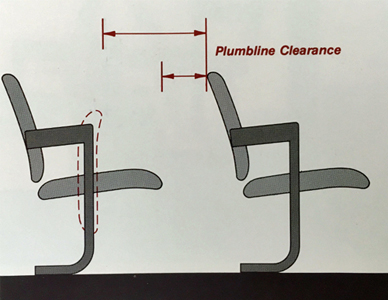
Building codes will provide auditorium seating layout and clearance requirements.
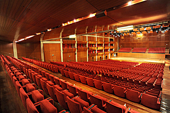
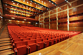
The Auditorium Giovanni Agnelli in Turin, Italy has variable ceiling height according to acoustic needs. Photo Credits: Centro Congressi Lingotto
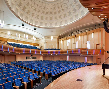
The historic 1927 Baldwin Auditorium at Duke University underwent renovations while incorporating significant sustainable design features and strategies such as energy and water efficiency, indoor air quality, and resource management, earning Silver Certification under the LEED™ for New Construction 2.2 Rating System. Pfeiffer Partners Architects. Photo Credit: Duke University
The following building program is representative of Auditorium space types.
| Description Tenant Occupiable Areas |
Qty. | SF Each | Space Req'd. | Sum Actual SF | Tenant Usable Factor | Tenant USF |
|---|---|---|---|---|---|---|
| Entrance | 2,096 | |||||
| Lobby | 1 | 1,500 | 1,500 | |||
| Entrance Vestibules | 1 | 96 | 96 | |||
| Coat Check | 1 | 150 | 150 | |||
| Retail Area | 1 | 200 | 200 | |||
| Media Library | 1 | 150 | 150 | |||
| Main Auditorium | 4,800 | |||||
| Seating (300 seats) | 1 | 3,600 | 3,600 | |||
| Stage | 1 | 1,200 | 1,200 | |||
| Support Spaces | 1,300 | |||||
| Projection/Control Room | 1 | 300 | 300 | |||
| Equipment Storage | 1 | 300 | 300 | |||
| Rear Projection Room | 1 | 400 | 400 | |||
| Public Toilets (Male | 1 | 120 | 120 | |||
| Public Toilets (Female) | 1 | 180 | 180 | |||
| Tenant Suite | 8,196 | 8,196 | 1.14 | 9,375 | ||
| Tenant Usable Areas | 18,750 |
The following diagram is representative of typical tenant plans.
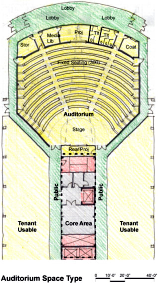
For GSA, the unit costs for Auditorium space types are based on the construction quality and design features in the following table . This information is based on GSA's benchmark interpretation and could be different for other owners.
The following agencies and organizations have developed codes and standards affecting the design of Auditoriums. Note that the codes and standards are minimum requirements. Architects, engineers, and consultants should consider exceeding the applicable requirements whenever possible.
The Automated Data Processing Center for Main Frame System (ADP Mainframe) space types is a facility for "vertical" data processing equipment including dense frame and rack-mounted processing systems with critical uptime requirements. ADP Mainframe space types include facilities for true mainframes, and for dense server farms arranged on vertical racks of equipment.

Typical server room
Typical features of ADP Mainframe space types include the list of applicable design objectives elements as outlined below. For a complete list and definitions of the design objectives within the context of whole building design, click on the titles below.
Occupancy: ADP Mainframe spaces fall under Business Occupancy B2, with Sprinkler protected construction. The GSA Acoustical Class B2 for spaces with concentrations of noisy equipment.
Raised floors: Raised floor is the preferred system for distribution of critical services (power, voice, data, and HVAC) in ADP Mainframe space types. Raised floors for ADP Mainframe may have low-pressure, high induction diffusers and should be constructed of concrete filled metal pans at 24" modules with pedestal and stringer support, with intermediate support.
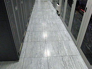
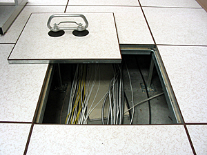
Raised flooring in place (left) and open (right) offers ease of access and storage of distribution systems.
Technological connectivity: Conduit and outlet boxes are installed for fiber-optic main horizontal and vertical backbone system and high speed communication lines for servers.
Dual path service lines for power: Dual path service lines ensure a constant power supply, which is critical to the operations of ADP Mainframe.
HVAC with redundant components: Computer equipment operates within specific ranges of air quality, temperature, and relative humidity levels. Significant variations of these levels in the ADP Mainframe environment could cause disruptions in equipment operation and decrease the life of the equipment. To ensure proper operation of the ADP Mainframe spaces, redundant mechanical systems with service provided 24 hours per day and humidity control are typically installed. Separate thermostat controls should be provided in each room, even in areas of 24-hour operation, which can be overridden by the building automation system. Also, copier rooms, printer rooms, and service units should have 100% direct exhaust to maintain good indoor air quality. For more information, see WBDG High-Performance HVAC.
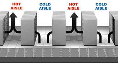
To control environmental temperature disparities and avoid downtime, a Best Practice is to use rows of equipment racks in an alternating arrangement of "cold aisles" and "hot aisles." See also Alternating Cold and Hot Aisles Provides More Reliable Cooling for Server Farms by Robert F. "Dr. Bob" Sullivan. The Uptime Institute: 2000.
Acoustic control: Sound baffles are provided at all acoustically rated partitions for the air supply system to control noise.
Uninterruptible Power Supply (UPS): Typically, emergency power and uninterruptible power are provided to meet all electrical requirements of the entire ADP Mainframe facility for at least 30 minutes. For more information, see WBDG Productive—Assure Reliable Systems and Spaces.
IT systems, including PCs, data storage, and data processing are energy intensive activities. However, many options can be considered to reduce energy use while also increasing efficiencies and reducing overall costs. Many organizations are developing plans to modernize data centers to realize their full potential while also reducing their impact on the environment. Best practices include utilizing the latest technologies such as virtualization technology and cloud computing. Additionally, data center design footprint can be reduced by using high-density cooling and power equipment. For areas of a data center that create a lot of heat, zone cooling devices can be deployed.
The following is a representative building program.
| Description Tenant Occupiable Areas |
Qty. | SF Each | Space Req'd. | Sum Actual SF | Tenant Usable Factor | Tenant USF |
|---|---|---|---|---|---|---|
| Control Room | 588 | |||||
| Control Consoles | 8 | 60 | 480 | |||
| Supervisor Console | 1 | 60 | 60 | |||
| Reference Manuals | 4 | 12 | 48 | |||
| Mainframe Room | 668 | |||||
| Mainframe Towers | 4 | 132 | 528 | |||
| System Administrator Console | 1 | 60 | 60 | |||
| HVAC Units | 4 | 20 | 80 | |||
| Server Room | 524 | |||||
| Unix Boxes | 20 | 12 | 240 | |||
| Control Terminals | 8 | 30 | 240 | |||
| Racks | 2 | 22 | 44 | |||
| DASD Room | 3,280 | |||||
| DASD Units | 32 | 100 | 3,200 | |||
| HVAC Units | 4 | 20 | 80 | |||
| Tape Room | 1,300 | |||||
| Tape Drive | 4 | 80 | 320 | |||
| Tape Storage | 80 | 12 | 960 | |||
| HVAC Units | 1 | 20 | 20 | |||
| Printer Room | 1,500 | |||||
| Laser Continuous Form | 1 | 140 | 140 | |||
| Laser Cut Sheet | 4 | 140 | 560 | |||
| Impact Printer | 1 | 140 | 140 | |||
| Burster | 1 | 140 | 140 | |||
| Work Table | 8 | 30 | 240 | |||
| Paper Storage | 4 | 20 | 80 | |||
| Control Consoles | 3 | 60 | 180 | |||
| HVAC Units | 1 | 20 | 20 | |||
| Communications Systems | 660 | |||||
| Controller | 16 | 30 | 480 | |||
| Telephone Console | 1 | 60 | 60 | |||
| Switches | 2 | 60 | 120 | |||
| Administrative and Support | 510 | |||||
| System Administrator Office | 1 | 150 | 150 | |||
| Data Administrator Office | 1 | 120 | 120 | |||
| Web Administrator Office | 1 | 120 | 120 | |||
| Shift Supervisor | 1 | 120 | 120 | |||
| Test Rooms | 2 | 200 | 400 | |||
| Electrical Room | 2 | 240 | 480 | |||
| UPS Battery Room | 2 | 120 | 240 | |||
| Fire Suppression | 1 | 20 | 20 | |||
| Housekeeping | 1 | 60 | 60 | |||
| Tenant Suite | 10,230 | 9,030 | 1.22 | 11,002 | ||
| Tenant Usable Areas | 11,002 |
The following is representative of typical tenant plans.
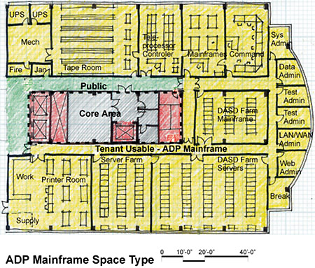
For GSA, the unit costs for ADP Mainframe space types are based on the construction quality and design features in the following table . This information is based on GSA's benchmark interpretation and could be different for other owners.
The following agencies and organizations have developed codes and standards affecting the design of ADP Mainframe spaces. Note that the codes and standards are minimum requirements. Architects, engineers, and consultants should consider exceeding the applicable requirements whenever possible:
Automated Data Processing Center for PC System (ADP PC) space types is a facility for "horizontal" data processing systems including floor- and counter-mounted units with non-critical uptime requirements. ADP PC space types include facilities for servers contained in individual equipment towers.
Because of the computer and electronic equipment housed within the ADP PC, the spaces require regulated temperature and humidity (usually accomplish by zoned systems), and reliable power 24 hours per day. Typical features of ADP PC space types include the list of applicable design objectives elements as outlined below. For a complete list and definitions of the design objectives within the context of whole building design, click on the titles below.
Occupancy: Occupancy Classification for ADP PC is Business Occupancy B2, with sprinkler protected construction and GSA Acoustical Class B2 for spaces with concentrations of noisy equipment.
Raised floors: Raised floors are the preferred system for distribution of critical services (power, voice, data, and HVAC) in ADP PC space types. Raised floors for ADP PC may have low-pressure high induction diffusers and be constructed of concrete filled metal pans at 24"; modules with pedestal and stringer support, with intermediate support.
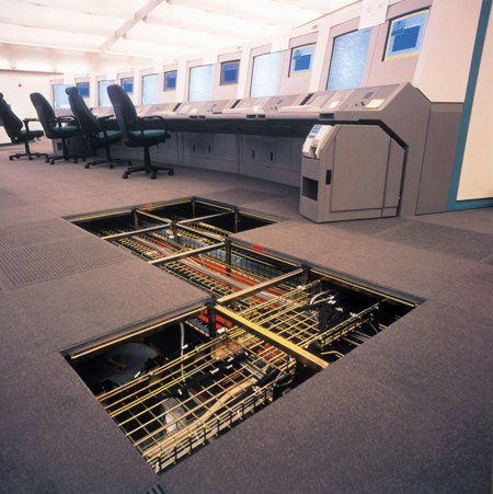
Raised flooring offers ease of access and storage of distribution systems.
Dual path service lines for power: Dual path service lines ensure a constant power supply, which is critical to the operations of ADP PC with concentrations of noisy equipment.
Redundant cooling unit: ADP PC space types are usually equipped with redundant cooling capacity to maintain the low temperature required by the computer equipment. This could consist of a split air-cooled, air-conditioning unit with 24-hour operation and setback thermostats. Acoustical transfer ducts should be installed at all acoustically rated partitions for noise control. For more information, see WBDG High-Performance HVAC.
Acoustic control: Sound baffles are provided at all acoustically rated partitions for the air supply system to control noise.
Uninterruptible Power Supply (UPS): Emergency power and uninterruptible power supply (UPS) are provided to meet all electrical requirements of the entire ADP PC (server) facility for at least 30 minutes. For more information, see WBDG Productive—Assure Reliable Systems and Spaces.


UPS systems range in a variety of capacities from small to server room size.
IT systems, including PCs, data storage, and data processing are energy intensive activities. However, many options can be considered to reduce energy use while also increasing efficiencies and reducing overall costs. Many organizations are developing plans to modernize data centers to realize their full potential while also reducing their impact on the environment. Best practices include utilizing the latest technologies such as virtualization technology and cloud computing. Additionally, data center design footprint can be reduced by using high-density cooling and power equipment. For areas of a data center that create a lot of heat, zone cooling devices can be deployed.
The following is a representative building program.
| Description Tenant Occupiable Areas |
Qty. | SF Each | Space Req'd. | Sum Actual SF | Tenant Usable Factor | Tenant USF |
|---|---|---|---|---|---|---|
| Facilities | 936 | |||||
| Supervisor Office | 1 | 100 | 100 | |||
| Support Technician Workstation | 2 | 80 | 160 | |||
| Reference Library | 4 | 12 | 48 | |||
| Magnetic Media Storage | 4 | 12 | 48 | |||
| Server Racks/Towers | 24 | 8 | 192 | |||
| Multiplexor/Controller Racks | 2 | 22 | 44 | |||
| Printer | 2 | 22 | 44 | |||
| HVAC Unit | 1 | 60 | 60 | |||
| Supplies and Parts Storage | 1 | 120 | 120 | |||
| LAN Switches/ Telephone Switches |
1 | 60 | 60 | |||
| Electrical Room | 1 | 60 | 60 | |||
| Tenant Suite | 936 | 936 | 1.31 | 1,227 | ||
| Tenant Usable Areas | 1,227 |
The following is representative of typical tenant plans.
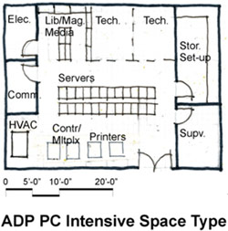
For GSA, the unit costs for ADP PC space types are based on the construction quality and design features in the following table . This information is based on GSA's benchmark interpretation and could be different for other owners.
The following agencies and organizations have developed codes and standards affecting the design of ADP PC spaces. Note that the codes and standards are minimum requirements. Architects, engineers, and consultants should consider exceeding the applicable requirements whenever possible:
The primary Navy aviation facilities this page will focus on are: aircraft maintenance hangars, paint hangars, jet engine test cells, and air traffic control.
Navy aviation facility design is typically approached with the intent of maximizing the functional uses for the squadrons as well as providing for future mission change. Facilities are generally standardized in size to allow for carrier-based aircraft to be accommodated in one size of facility and for larger marine patrol aircraft to be housed in another facility type.
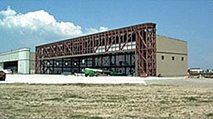
Aircraft Maintenance Hangar with header truss roof framing system
The basic function of an aircraft maintenance hangar is to provide flexible space that accommodates change in base loading and to provide optimum use of the flight line for aircraft access. The single most important factor in determining the hangar design and layout is the hangar structural roof-framing system. The most valuable real estate at an airfield is the flight line. So, the roof framing system selected for the hangar design must optimize access to the flight line.
Until recently, the Navy has mandated the use of the cantilever roof framing system. This system minimizes flight line columns that restrict aircraft movement. The cantilever system also lends itself to future expansion by removal of an end wall and extending the hangar down the flight line. However, a cantilever system is an inefficient method for supporting loads, is prone to larger deflections, and is more difficult to erect. The cantilever designer needs to carefully consider the effect of erection sequencing, actual versus predicted loads, and environmental conditions during the fabrication and erection.
The header truss system can span modules or the entire flight line face of the building resting on supports at the front corners of the hangar. The remaining walls of the hangar are conventionally framed. Lateral support is provided through the walls and the truss supports. Intermediate support to the truss is provided in the plane of the roof through a diaphragm, dedicated horizontal truss bracing, or a combination of the two.
The structural efficiency and stiffness decrease exponentially as the span of the truss increases. Increasing the depth of the truss can offset this. Practical limits of transporting fabricated hardware, erecting the assembled truss and the lateral bracing system limit the truss depth to approximately 7.5 meters. A header truss virtually precludes the use of an expansion joint along the centerline of the hangar bay and extends the practical thermal expansion limit. The header truss system also requires the flight line frontage be dedicated to structural supports. Construction documents for a header truss must clearly indicate the camber requirements. The designer must carefully consider the influence that temperature and erection rigging will have on completing the final connections as well as the final camber.
The Navy has recently agreed to allow the hangar framing system to be based on an economical decision in unison with the long-range planning of the airfield. The Navy is continually searching and assessing innovative ways to improve the quality of the workplace for the sailors, operators, and maintenance personnel by taking the best of today and building a better aviation facility for tomorrow.
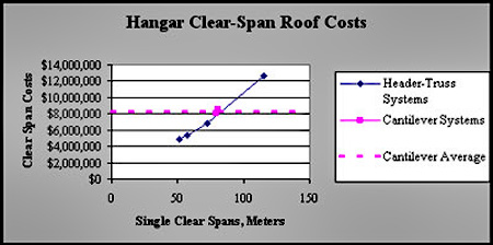
Graph of Economic Comparison of Header Truss versus Cantilever Truss
Paint hangers are considered spray areas instead of spray booths. The primary design criteria of interest for Navy paint hangars is design airflow. The Navy has carefully evaluated ventilation requirements for paint hangars and follows the guidance prescribed for industrial ventilation as outlined in Industrial Ventilation: A Manual of Recommended Practice for Design by the American Conference of Government Industrial Hygienists (ACGIH) that allows designers to use a flow range between 50 and 75 cfm/ft². The Navy recommends 50 cfm/ft² because hangars are very large, tall, deep work areas that dilute paint fumes very quickly. The Navy's paint hangar ventilation goals are to: prevent explosion or fire; protect the employee from hazardous exposure; to provide a quality paint product; and to ensure good housekeeping of the paint bay. In a 1997 OSHA letter to the Navy, OSHA "considered these hangers to be spray areas since painting was incidental to the specific area that is being treated." There is no specific OSHA standard that pertains to ventilation rates other than maintaining the concentration of the vapors and mists in the exhaust stream of the ventilation system to not more than 25 percent of the lower flammable limit.
There is no existing Industrial Hygienist exposure-monitoring data throughout the Navy indicate for corrosion control hangers that indicate worker overexposure. Regardless of airflow (50-100CFM or more), Navy designers anticipate that respiratory protection would still be required as the primary containment means as opposed to the building ventilation system.
Jet Engine Test Cells provide an enclosed facility for out-of-airframe testing of Navy/Marine Corps jet engines that is intended to provide repeatable results with a standard day correction factor of one (1) as the goal-the test results for indoors and outdoors would be equal. Enclosed cells also reduce noise emission to within OSHA standards. The NAVFAC standard aircraft engine test facilities are complex to design, build, and maintain because they are extensions of Navy/Marine Corps aircraft systems rather than routine buildings. Test cell facilities are designed with special air intakes and exhaust to ensure engine performance consistency and to suppress noise to OSHA acceptable levels. Reduction of heat and vibration from engine exhaust are additional design concerns. NAVAIR aircraft controls and instrumentation are integrated into test cell design to verify satisfactory engine performance prior to returning engine to fleet inventory.
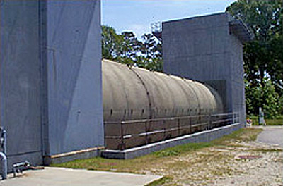
Navy's traditional out-of-airframe jet engine test cell lined with acoustical pillows and perforated stainless steel inner panels
The NAVFAC Criteria Office and Atlantic Division Naval Facilities Engineering Command recently sponsored a new design innovation for jet engine test cells in response to acquisition cost reduction and constructability concerns. The new design features a square exhaust augmenter instead of the elliptical configuration normally employed. The new design provided a $500,000 savings in the initial construction cost as well as an anticipated savings of $100,000 in reduced maintenance costs. The jet engine test cell facility's aero/thermodynamic performance is essential to consistent engine test results and preventing accelerated building deterioration. The engine manufacturer requires verification of the engine repairs and reassembly by repeatable, prescribed engine test results. Minor airflow variations can significantly distort engine performance or prematurely fail building components. The Navy has long been recognized as the world's leader in aircraft engine test system design. The new design has correlated with the previous standard for acoustical, aero/thermodynamic, and general engine performance testing. Advanced mathematical modeling at the Naval Facilities Engineering Service Center (NFESC) and physical scale modeling at The Ohio State University Aeronautical Research Center were conducted prior to changing the Navy's standard design. The Architect/Engineer of record worked with a team of Navy experts to identify and resolve problems from concept through final acceptance. The construction contractor from Seely, Texas partnered with the design team to build the prototype facility at Naval Air Station (NAS) Oceana, Virginia Beach, Virginia. Naval Air Warfare Center Lakehurst and NFESC jet engine test cell experts consulted with the Navy's design/construction team throughout the process to ensure the original test cell performance criteria was preserved in the next generation version.
The Architect/Engineer of record encountered significant engineering challenges throughout the design and construction of the square augmenter test cell. The Architect/Engineer of record verified the new test cell aero/thermal behaved consistent with previous Navy Round Exhaust Augmenter Cells (a large exhaust pipe). The most important criteria for engine performance was to ensure that the primary inlet velocity was laminar and limited to 50 feet per second in the mathematical, 1/12th physical scale, and full-scale model testing. The Architect/Engineer of record faced demanding structural challenges as well to verify the new augmenter connections would survive the Navy's jet engine testing harsh environment. In addition to high acoustical and jet blast pressures, the new augmenter had to withstand 500-degree temperature changes for 10,000 cycles. All connections had to be designed to ensure that the augmenter acoustical panels returned to the original position after experiencing the cyclic 500-degree temperature change.
The Navy modeled and built two square augmenter panels at the Engineering Services Center to demonstrate performance of the proposed design connection details for the new precast concrete to stainless steel acoustical liner sheets in the augmenter. The demonstration section verified: a) that stainless steel panel alignment was maintained after 20 cycles of thermal loading, and b) that heat transfer was not detrimental to the lightweight precast concrete at the connection points. After simulating an F-110 engine in full military after burner at NFESC test lab in Port Hueneme, California, the Navy found the inner stainless steel panel face reached 500 degrees Fahrenheit above ambient with only 150 degrees transferred to the precast concrete inner surface. Panel alignment from continuous expansion and contraction and heat transfer concerns were mitigated from the design.
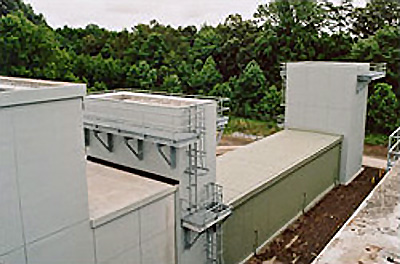
Precast lightweight concrete for the outer square shell of the augmenter lined with acoustical pillows and perforated stainless steel inner panels
For the preliminary square augmenter aero/thermal evaluation (August, 2001) three engines (TF 30, F-110, and the F404) tested within performance parameters per the test director; the test cell exhibited primary inlet velocity airflow problems as documented by the F-110 data for Engine Run Room profile at maximum AB power. Resolution of this airflow problem was carefully evaluated by a team of experts. From the conceptual design all the way through the prototype facility construction, the common thread that ensured a successful product delivery was the partnering and teamwork to attack a problem and develop a solution that was best for the end user.
The construction phase went better than any other test cell constructed by the Navy prior to that time. Partnering and teamwork throughout the construction phase was instrumental in resolving complex issues. Final acceptance was facilitated by the formation of an expert aero/thermal team to identify concerns and resolve issues quickly. All team members were committed to delivering a quality product, on time, and within budget.
Specialized knowledge and expertise were required to design, construct, and accept the NAS Oceana test cell facilities. The Architect/Engineer, the Construction contractor, NFESC, Naval Air Systems Command (NAVAIR), and Atlantic Division Naval Facility Engineering Command (LANTDIV) jointly provided technical support for the NAS Oceana square augmenter test cell. Good communications and constant involvement eliminated conflicting guidance to the contractor. The customer is very pleased with the end product he received as demonstrated by his production testing of 36 F-404 engines within the first 2 months since final acceptance.
The design was a multi-disciplined approach to facility engineering with a heavy emphasis on the aero/thermal, acoustical, and structural performance of the test cell exhaust augmenter. The Navy's square augmenter design is a lightweight reinforced precast concrete tees with acoustical stainless steel panel treatment that spans between the precast concrete webs. The augmenter structural frame is a combination of a rigid steel frame and precast concrete tee that had special temperature isolation points at the connection points to prevent the temperature absorbed by the steel inner liner surface from being transferred to the concrete that would be susceptible to spalling. The augmenter absorbs and cools the engine's hot exhaust gases requiring components to expand and contract over a 500 degrees Fahrenheit design temperature change and return to its original configuration without misalignments. The 500 degrees Fahrenheit design temperature change was the governing structural loading condition for design. The augmenter connections were one of the most challenging issues confronting the design team. The contractor/designer team partner ultimately produced the optimum solution. The stainless steel design panels had to be free to expand and contract in all directions yet return to their original position and remain stable through engine testing. The team ultimately agreed upon a snug tight pin approximately at the panel's center of mass with slots at other locations on the panel to provide for a temperature expansion and contraction. The precast outer shell has the same tight tolerances for fabrication and erection; however the temperature change was limited to 150 degrees Fahrenheit above ambient.
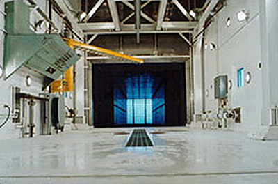
Augmenter stainless steel square cross section
The design team learned from the mathematical and physical scale modeling that every component within the test cell interrelated to the performance of the rest of the cell. The exhaust stack was modified by replacing the exhaust ramp with turning vanes and the exhaust stack cross section area was reduced to save construction costs and more evenly distribute the air flow. The secondary stack that is used to mix and cool the engine exhaust gases was also slightly reduced in cross section.
The construction of the innovative design presented its share of problems. The exhaust stack structural steel failed during the first engine test. The designer used steel struts to support the turning vanes that were fixed on both ends. The traditional Navy exhaust ramp provides for a fixed condition at the base and a roller at the strut top to allow up to 4" of thermal movement. The struts buckled laterally. A field fix provided a heavy angled bracket with slotted connections to provide for expansion due to over a 700-degree temperature change when the F-14 engine was in full military after burners. The exhaust stack is lined with acoustical panels that protect the concrete from the high exhaust temperatures. These panels are designed to expand and contract in any direction. The inner skin is a perforated stainless steel sheet used to encapsulate thermal and acoustical insulation. Normally, the 18-gauge stainless steel material takes the high acoustical loadings because the perforations instantly equalize the pressure. Unfortunately, the acoustical panels are held in place with a friction connection with carefully controlled anchor tension. Due to the high temperature change, the panels need to be free to expand and contract. The installer apparently overtightened the bolts and created a binding condition when the panels tried to expand resulting in a buckling of the panel skin.
The Navy's structural design of Air Traffic Control (ATC) Tower Facilities is based on ASCE 7 Minimum Design Loads for Buildings and Other Structures for dead, live, and wind loading, UFC 1-200-01 General Building Requirements, UFC 3-310-04 Seismic Design for Buildings and FEMA 368. The Navy has recently designed and constructed three towers in the Norfolk/Virginia Beach area where wind controlled the design lateral loads by a significant amount (33.3% above horizontal base shear from seismic loading). NAS Whidbey Island is currently going through final design and NAS Brunswick is in the design request for proposal stage. NAS Whidbey Island and NAS Brunswick have treated their tower designs as an essential facility in accordance with FEMA 368.
The three east coast towers use a concrete shear wall box system and were designed under the old P-355 (TM 5-809-10) criteria. The NAS Whidbey Island tower will be the Navy's first air traffic control tower designed under the performance based criteria required by UFCs 1-200-01 and 3-310-04 and FEMA 368. The Whidbey Island design team decided to use steel braced frame. The design occurrence selected for NAS Whidbey Island was a once in 2500-year occurrence.
The Force Protection design requirements for an Air Traffic Control Facility shall be according to the UFC 4-010-01 DoD Minimum Antiterrorism Standards for Buildings. Generally, the number of air traffic controllers is less than 10 people and the facility is rated as un-inhabited. For major activity at ATC facilities, the air traffic controllers number around 15, invoking the requirement for a progressive collapse analysis.
The Navy feels the selection of the seismic performance objectives should be carefully based on whether the structure is mission essential, not because ACTs appear in the essential facilities category in the seismic use group. The owner, architect, and structural engineer of record should carefully review the performance objectives as described in UFCs 1-200-01 and 3-310-04 before final design of the tower is initiated. The Navy believes emergency and alternate communication systems, plans for quickly diverting air traffic to alternate fields, and the presence of temporary towers can all be considered a redundant facility to, perhaps, assign the facility a life-safety occupancy versus immediate occupancy.
The Navy is currently evaluating its policy and criteria for Air Traffic Control Towers in an effort to clarify ambiguities that might exist between the UFCs 1-200-01 and 3-310-04 and FEMA 368. The Navy expects to issue guidance on static versus dynamic analysis by September 30, 2004, particularly for air traffic control facilities falling in seismic design category D, E, or F for either the FEMA or UFCs 1-200-01 and 3-310-04 analysis.
by Joseph C. Dean, P.E. and Steve Geusic, P.E., for the Director, Corrosion Policy & Oversight (DCPO), (DASD (Materiel Readiness))
Updated: 10-14-2021
Facilities that are located on aviation installations (i.e., bases, air stations, airfields, etc.) endure high impact and dynamic stresses due to operations and related demands. Those facilities may include hangars, runways, taxiways, pipelines and tanks for petroleum, oils, and lubricants (POL), wash racks, hush houses, and jet engine test cells. Supporting facilities include power distribution and conversion, barracks, administration buildings, sewage and water treatment, water distribution and sewage collection, roads, communication structures, and warehousing. Sub-structures include fencing, windows, doors (especially hangar doors), roofs, plumbing, heating, ventilation, and air conditioning.
Aviation Installations are located in a variety of different environments, each with their own unique impacts on materials degradation and corrosion. For instance, Aviation Installations located in coastal zones, with their inherently higher ESC, will likely exercise higher levels of corrosive deterioration. In these varied and ever-changing environments, designers and maintainers must be vigilant to ensure that the best materials, construction processes and sustainment practices are utilized. A facility’s design details must be selected with life-cycle effectiveness and durability considerations to ensure that the entire system of fixed and movable structures act as one to guarantee needed availability for the operating forces.
The Facilities Corrosion Impacts on Operations and Missions Table provides insights into how facilities categories can be impacted by corrosion. Environmental Severity Classifications (ESC) are described in UFC 1-200-01 DOD Building Code and further described in the ESC CPC Resource Page. The Corrosion Prevention and Control (CPC) efforts to keep an aviation facility located in ESC Zones 4 and 5 operationally ready are challenging and requires sound planning, design, construction, and sustainment efforts commensurate with those conditions. Photo 1 shows an aviation facility adjacent to a waterfront in Zone 5. All of these facilities are at high risk for accelerated corrosion impacts on operations and mission creating challenges for both sustainment and operations personnel.

Photo 1: Showing waterfront facilities and an airfield in top center. Source: MC 1st Class Christopher B. Stoltz / U.S. Navy via Reuters file
The Whole Building Design Guide (WBDG) provides resources for designers, maintainers and facility managers that directly address broader issues for aviation facilities, including:
Naval Air Stations, Air Force Bases, Army Airfields, Reserve fields, and Coast Guard bases emulate small cities containing a broad combination of facility categories. This Knowledge Page will discuss the complexities of managing CPC across aviation-focused installations. Many DoD facilities are maintained by contracts; these contracts must include strong quality assurance (QA) and quality control (QC) programs. Contracts such as Design-Build, where the contractor hires the architect and engineer of record, must include criteria which will identify material selection guidance by ESC Zone and Cathodic Protection practices (e.g., design, installation and sustainment) in the Request for Proposal (RFP). See also the CPC Acquisition Issues Resource Page.
Aviation facilities’ CPC, including supporting structures, requires the interaction of many engineering disciplines such as structural, electrical, environmental, mechanical, and civil and specialty engineering areas such as cathodic protection, geotechnical, material selection, and expertise in paints and coatings. Each discipline has an essential role to play in ensuring that aviation facilities are designed and constructed to be sustainable, especially those near waterfront locations.
The CPC related to planning and design of aviation facilities and supporting structures requires a thorough understanding of the many aspects of the area where they are constructed and associated design characteristics. These can include:
UFC 1-200-01 DoD Building Code, provides very specific guidance for design, construction and sustainment actions related to CPC. The UFC 1-200-01 Appendix ESC for DoD Locations, identifies the ESC Zone for each of the DoD Installations around the world, which then drives the selection of the types of materials and processes that should be used for corrosion-prone locations.
The CPC highlights from several of the most relevant UFC and UFGS documents for aviation facilities are provided below:
UFC 3-190-06 Protective Coatings and Paints: Provides requirements and technical guidance for the effective use of paint-type coatings to protect common materials such as metal, concrete, pavements, gypsum board and wooden structures at military activities from deterioration. This UFC applies to all Navy, Air Force, and Army service elements and contractors. Requires paints and coatings that are durable and minimize the need for preventative and corrective maintenance over the expected service life of the component or system. Note that this is a significant update from previous versions. Different materials will be used based on local environmental conditions (See UFC 1-200-01 DoD Building Code as required in the UFC). Corrosive environments, which require additional corrosion protection, are those project locations which have an Environmental Severity Classification (ESC) of C3, C4 or C5. Humid locations are those in ASHRAE climate zones 0A, 1A, 2A, 3A, 3C, 4C, and 5C (as identified in ASHRAE 90.1). Defines coating systems for specific uses. See Photo 5 for an example of the uV degradation of an organic coating system.
UFC 3-250-04 Standard Practice for Concrete Pavements: The UFC discusses the realities of the reaction of steel and de-icing salts and corrosion behavior when water is able to gain access. The use of coated dowels and reinforcing steel should be considered in the presence of seawater. Alkali-silica reactions as shown in Photo 2 are discussed in this UFC, which provides information on their risk, potential damage, and possible solutions. Much has transpired since this UFC was published, including extensive research into heat-resistant mix designs and the categorization and application of ESC Zones (see UFC 1-200-01).
Photo 2: Alkali-Silica Reaction in Concrete Source: D, CPO
UFC 3-260-01 Airfield and Heliport Planning and Design: The UFC mentions corrosion control facilities, aircraft rinse facilities, and aircraft wash racks in the context of corrosion control. Those facilities require special attention to ensure operational integrity to both meet requirements and prevent environmental pollution.
UFC 3-260-02 Pavement Design for Airfields: The UFC provides an extensive description and discussion related to pavement joints and the associated need to establish and maintain joint integrity. Joint design and construction poses a serious risk factor related to CPC of pavements and the aircraft that utilize them. The UFC provides extensive guidance insights into pavement design, and while the word “corrosion” might not be used, the impact of failed subbase, water intrusion, erosion, concrete cracking allows access to steel reinforcing that causes spalling and foreign object damage (FOD). In sandy soils, where drainage structures are installed under ramps and pavements, the erosion of the subbase into the drainage structure through pipe joints allows the pavements to crack and fail as shown in Photos 3 and 4. The UFC also discusses alkali-silica aggregate reaction.


Photos 3 and 4: Runway asphalt deterioration examples. Sources: (Left) Guy Choate, GARVER USA and (Right) Dwayne Page, Station Manager, WJLE News
UFC 3-270-01 O&M Manual: Asphalt and Concrete Pavement Maintenance and Repair: Mentions the hazards of using gypsum-based concrete (calcium sulfate) repair materials and the presence of free sulfates in the promotion of corrosion in reinforcing steel in pavements. Crack sealing can become a corrosion and FOD problem if not executed properly. Note also that UFC 1-200-01 update requires application of new corrosion and related environmental severity guidance and was published after this UFC.
UFC 3-570-01 Cathodic Protection: Delineates mandatory uses of Cathodic Protection (CP), many of which can be found at aviation installations. The UFC provides extensive information and guidance on which kinds of facilities would benefit from CP systems and what kinds of CP systems are appropriate for specific facilities.
UFC 3-570-06 Operation and Maintenance: Cathodic Protection Systems contains detailed procedures for sustaining CP Systems.

Photo 5: UV Degradation of Organic Coating Systems Photo Source: D, CPO
UFC 3-600-01 Fire Protection Engineering for Facilities: Requires that above ground piping and embedded pipe utilized in fire-protection systems be corrosion-resistant (ASTM A312). For service mains and laterals, “provide appropriate corrosion protection based upon pipe materials and the corrosive properties of the water supply and earth.”
UFC 3-601-02 Operation and Maintenance: Inspection, Testing and Maintenance of Fire Protection Systems: Foam and Foam-Water Systems are discussed relative to maintenance and corrosion monitoring.
UFC 4-121-10N Design: Aircraft Fixed Point Utility Systems: Requires the use of UFC 1-200-01 which was recently updated to emphasize CPC and the corrosion risks in ESC Zones. Corrosion-resistant coatings and materials are mentioned.
UFC 4-133-01 Air Traffic Control and Air Operations Facilities: Addresses corrosion concerns and requirements for Control Cab Window Mullions), Catwalks, and Exterior Observation Grates.
UFC 4-171-01N Design: Aviation Training Facilities: Provides extensive guidance on corrosion control for finishes and materials. Specific design guidance is provided to address high-moisture impacts, to include ventilation (use corrosion-resistant materials in duct work), finishes and pool design. All components of the HVAC system should be made of corrosion-resistant materials. See the UFC for additional specific guidance.
UFC 4-211-01 Aircraft Maintenance Hangars: Discusses CPC and paint facilities. The coating requirements in the Protective Coatings section include guidance on painting all non-finished items such as exterior ferrous metals, hangar doors, interior ferrous metals related to primary and secondary steel framing inside Aircraft Maintenance Bays and fuel-resistant resinous flooring. The section on Sealed Concrete requires the use of sealers to prevent corrosion.
UFC 4-211-02 Aircraft Corrosion Control and Paint Facilities: "Provide(s) architects, engineers, and construction surveillance personnel with the essential, minimum requirements for the design and construction of Aircraft Corrosion Control or Paint Finishing Facilities." These types of facilities are focused on sustaining aircraft and are mentioned in this UFC to emphasize their operational importance. The UFC discusses CPC of the equipment side of installation operations, which include rinsing, stripping, and painting, and the chemical used in the stripping process can be corrosive to the facility infrastructure, containment, ventilation, and flooring systems.
UFC 4-212-01N Navy Engine Test Cells: Addresses the design criteria essential for the design and construction of Jet Engine Test Cells (JETC). See also the Table Inspection and Test Frequency.
UFGS 07 41 13 Metal Roof Panels: Discusses considerations for corrosion protection from chemical and uV radiation including primers, factory finishes, abrasion resistance, and surface protection from damage. It also discusses corrosion-resistant fasteners and miscellaneous metal framing, screws and rivets.
UFGS 07 61 14.00 20 Steel Standing Seam Roofing: Delineates corrosion resistant construction requirements for materials, warranties, closures and fasteners.
UFGS 08 34 16 Corrosion Control Hangar Doors: Delineates standards for hangar-door design and for the work experience of hangar-door manufacturers. This UFGS also explains installer requirements and discusses corrosion-resistant materials.
UFGS 09 90 00 Paints and Coatings addresses "requirements for painting of new and existing, interior and exterior substrates." Discusses corrosion and invokes UFC 1-200-01 DoD Building Code. Delineates ESC requirements for ESC Zones C3, C4 and C5 and ASHRAE 90.1 humid locations in climate zones) A, 1A, 2A, 3A, 4C and 5C. It includes contractor qualification requirements (SSPC QP 1, QP 2, etc.) and refers to SSPC, NACE, and MPI Standards. Topics include coatings, corrosion, rust, deterioration, mold, and mildew. See the Paints and Coatings Knowledge Area and the Coatings Modules in the WBDG Continuing Education Section. Many UFGSs for paints and coatings are listed at the end of this page including UFGS 09 96 00, UFGS 09 97 02, UFGS 09 97 13.00 40, UFGS 09 97 13.15, UFGS 09 97 13.16, UFGS 09 97 13.17, UFGS 09 97 13.27 (see below for links to these UFGS).
UFGS 26 56 20 Airfield and Heliport Lighting and Visual Navigation Aids: Section 1.6.6 Prevention of Corrosion states the requirement to protect metallic materials from corrosion. Aluminum should not be used in contact with earth or concrete, and aluminum conductors should not be used at all. Steel conduits installed underground must be protected from corrosion.
UFGS 32 13 13.43 High Temperature Concrete Paving for Airfields Using Lightweight and Traprock Aggregates discusses heat-resistant concrete-mix design for high-temperature-resistive pavements using lightweight and traprock aggregates. Also states mix design to mitigate alkali-silica aggregate reaction and sulfate attack.
UFGS 32 13 14.13 Concrete Paving for Airfields and Other Heavy Duty Pavements discusses alkali-silica reactivity aggregates, combinations of cementitious materials and concrete mix design.
UFGS 33 52 43.11 Aviation Fuel Mechanical Equipment provides important CPC requirements for various pieces of the aviation fuels system. Coating requirements are defined to include surface of tankage as well as connectors, valves, and mechanical equipment. Corrosion-resistant materials are to be used in components such as grounding straps and pump components.
CPC plays a significant role in aviation installation facility Sustainment, Restoration and Modernization (SRM) and Operations and Maintenance (O&M) of DoD installations. SRM and O&M are complimentary efforts that leverage good engineering practice and requirements identification to ensure that the CPC program is robust and consistent with ensuring that the installation and its facilities are operationally ready. In order to determine the best course of action, it is often essential to determine the cause and rate of corrosion. Specific areas of corrosion often visible on an aviation facility include:
It is relatively easy to resolve visible deterioration above ground, but more difficult to protect buried and hidden structures. If conduit steam lines are used, for example, the weak, more corrosion-prone areas of the utility should be monitored as part of a preventive-maintenance inspection program. Hangar-door tracks and mechanical works become problematic because of the immense weight impact on components that wears on coating protections.
While the criteria listed along with the discussion of locations is not all-inclusive, it does contain some insights into the magnitude of designing, constructing and sustainment of structures found on aviation installations in ESC Zones 1 through 5. Considering and addressing these issues will assist in achieving a corrosion-resistant design that supports mission effectiveness and meets life-cycle expectations.
The broad collection of Aviation Facility categories on an installation such as hangars, runways, roads, paved areas, administrative, barracks, dining, generation and distribution of utilities, waste and water treatment structures presents a challenge for the facility manager. Many facility categories are both visible and hidden from view, all of which are at risk of corrosive degradation. Some corrosion becomes immediately dangerous. If a concrete apron is not designed to handle the heat signature of aircraft in the inventory, it will degrade and result in a high potential for FOD potentially damaging the aircraft. Undiscovered underground-utility corrosion can result in loss of steam services. Petroleum-related system corrosion can produce a devastating series of events, including loss of product, suspension of operations, environmental violations, negative publicity, and heavy financial costs.
There are other CPC Source web pages addressing common issues such as fencing, doors, cathodic protection and pavements that relate to aviation facilities. Establishing and conducting a thorough maintenance management program that includes inspections, a recurring maintenance program, service calls, and related SRM actions, will provide confidence that corrosion-driven failures have been minimized. By conducting an active maintenance management program, SRM managers will be able to convey essential knowledge to designers and constructors to improve newly constructed and repaired facilities.
There is typically no single CPC criteria reference, so designers, constructors and sustainers often have to do research into multiple criteria and guidance documents to determine the best CPC approach. That effort will result in newly constructed or repaired facilities that meet durability and operational needs. Many of those resources are listed below.
Download and print or have available electronically during class. No hard copies provided.
Aircraft hangars are commonly referred to as "glorified garages" for airplanes. They can vary from simple "shade" structures that protect all or parts of the aircraft from the elements to complicated environmentally controlled maintenance facilities in which robots apply radar absorbing coatings. However, since planes are designed to fly, it is essential to minimize their maintenance time in the hangar and maximize their availability to fly.
The Armed Services have developed definitive designs for hangar facilities to house and maintain their aircraft. Many of these definitive designs are shown in UFC 4-211-01N Aircraft Maintenance Hangars: Type I, Type II and Type III. Much of the criteria for the design comes from AFM 32-1084 Facility Requirements.
In the commercial aircraft sector the designer needs to rely on Facility and Planning Criteria that are issued by the aircraft manufacturers for their aircraft or a third party compilation of data. For example, the Boeing aircraft characteristics can be found on the company's website. The designer must follow local building codes and integrate the characteristics of all possible aircraft that can populate the hangar to develop the space requirements for the intended use of the hangar.
There are five types of spaces in hangar facilities:
Careful analysis of the following will allow designer to determine the space needs for general spaces listed above common to aircraft hangars.
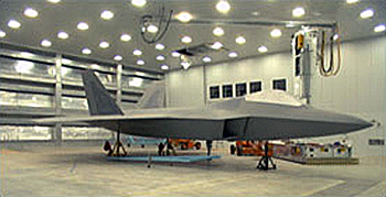
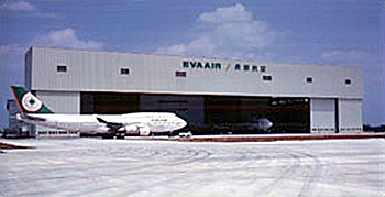
F22 Fighter Aircraft Robotic Coating Facility, Lockheed Martin Aeronautical Systems Company—Marietta, Georgia Photo Credit: Burns & McDonnell
160–meter clear span Aircraft Maintenance Facility for Evergreen Airways in Taiwan, Republic of China Photo Credit: Burns & McDonnell
Step 1: Determine the types and number of aircraft which populate the hangar.
During this initial stage, input is needed from the hangar's future owner about his aircraft fleet. Information such as the following:
Step 2: Determine the Maintenance Function of the Hangar Facility.
Input is needed from the owner with regards to the maintenance that will be performed on the aircraft in the hangar. This can vary from no maintenance at all to complete overhaul of the aircraft. Different levels of maintenance are required by the Federal Aviation Administration for certain aircraft currently in operation.
Step 3: Compile the Aircraft Characteristics
Some references to obtain physical characteristics and maintenance requirements of aircraft are as follows:
Step 4: Determine Hangar Space Requirements
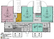
Coating /Composite Restoration Facility for Fighter Aircraft at Langley AFB View enlarged plan Photo Credit: Burns & McDonnell
To determine the most efficient use of hangar space use templates representing the aircraft and floor plans drawn at the same scale. Arrange the templates in various combinations to the make the most efficient use of space and permits maintenance operations.
Minimum separation distances between aircraft and minimum distances between the aircraft and other obstructions are defined in some building codes and in AFM 32-1084Facility Requirements.
Another factor to consider in sizing the hangar space is the fire protection requirements. The National Fire Protection Association standard, NFPA 409: Standard on Aircraft Hangars establishes four different groups of hangars based on their size and construction type. In general, the smaller the hangar space the less expensive the fire protection and utility requirements.
When sizing the hangar space, do not overlook tail heights, the height and width of the hangar door openings, the structural depth of columns and trusses and the turning radius of tow vehicles connected to aircraft. Also in larger hangars, distance to means of egress become a concern and should be laid out to meet local codes and NFPA 101: Life Safety Code.
Step 5: Determine space needs for the Maintenance Shops and Warehouse
The maintenance shops and warehouse provide space and storage for required maintenance activities such as fabrication shops, airframe repair, engine repair, aerospace systems repair, battery servicing area, cryogenics maintenance, interior finishes repair and nondestructive testing laboratory.
For Air Force Facilities, AFM 32-1084 Facility Requirements lists maintenance shop space requirements for different squadrons of aircraft. Similar rational should be used in the commercial arena with input from aircraft manufacturers.
The Federal Aviation Administration mandates procedures to be followed by operators when establishing aircraft inspection intervals and overhaul times.
Step 6: Determine space needs for the Office/Administration Area
The space needs in the Office/Administration area are similar to those required in any office building. The general rule of thumb according to Office Finder is 175 to 250 square feet of useable space per person.
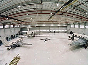
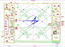
Lockheed Martin Corporate Hangar Facility—Baltimore, Maryland Photo Credit: Burns & McDonnell
Determining the space need for the utility systems is highly dependent on the hangar maintenance function and the available utilities. In some corrosion control hangars the HVAC requirements are so stringent that the mechanical rooms can be as large as the hangar space itself. Also in corrosion control hangar spaces the mechanical rooms should be located adjacent to the hangar space and with an exterior wall for outside air requirements. The HVAC in the hangar space must be integrated with the fire detection system to shut down in case of a fire.
In general, the hangar space usually requires fire protection using water mixed with an Aqueous Film Forming Foam (AFFF). This can be applied by an overhead system or water cannons mounted near the floor. If the existing fire water pressure isn't adequate, the fire protection system may require a reservoir and booster pumps to satisfy the demand of the hangar space. The National Fire Protection Association standard, NFPA 409: Standard on Aircraft Hangars establishes fire protection criteria for hangars based on their size and construction type. Another resource is the owner's insurance carrier who should have input into the fire protection and detection systems.
The electrical requirements of the hangar facility should meet the requirements of NFPA 70: National Electrical Code®. The hangar space should be classified as hazardous or nonhazardous according to NFPA 70 and the electrical installations designed accordingly. Electrical equipment in the hangar space should be waterproof, NEMA Type 4 (minimum rating) when deluge sprinkler protection is provided. Various power supply voltages and frequencies are required in the facility because Aircraft and Ground Support Equipment operate on different voltages and frequencies than normally provided by the public utilities.
One of the largest single design elements to be selected is the type of hangar door to be utilized. There are several different types (sliding, vertical lift, bifolding, fabric, etc) and each type has advantages and design implications for the overall structure.
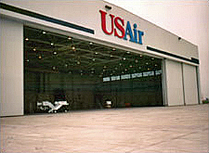
412–foot Clear Span Maintenance Hangar for US Airways in Indianapolis, Indiana Photo Credit: Burns & McDonnell
Sustainable design should be incorporated into every building design so the building can perform efficiently without wasting energy during its lifetime. The hangar area is particularly susceptible to heat loss as the hangar doors are opened for aircraft movement.
The next generation of aircraft is larger and heavier than current aircraft that will make many existing hangar facilities obsolete. For a primer see Burns & McDonnell's Special Report to the Airline Industry, How Will New Large Aircraft Affect Your Airport Facilities .
As Aircraft manufacturers move towards composite materials and avionics become more sophisticated, the hangar maintenance facility will need to respond to the new requirements. The aircraft maintenance facility will resemble an industrial facility which will require remediation of toxic effluents, air pollution permits, safety standards for working in hazardous areas and a high tech facility with laboratories and clean rooms.
The aviation industry is a high profile industry and is a target for terrorist attacks. Future building designs will incorporate higher levels of security and force protection/anti-terrorism standards.
Sustainability has become an increasing priority for facilities projects. However, since the terrorist attacks of September 11, 2001 building owners and occupants have been paying more attention to facility security and safety issues. On the surface, it may appear that secure/safe design has little relationship to sustainable design. Yet, security and safety measures, such as those for anti-terrorism, must be considered within a total project context, including impacts on occupants and the environment, regardless of the level of protection deemed appropriate. Today's security design is based on a multi-hazard approach, that is, looking at the impact of all hazards on a project: natural, criminal, terrorist, chemical/biological, and accidental.
This Resource Page provides designers with an understanding of the interactions between security/safety and sustainability objectives by emphasizing the 'whole building' or integrated design process, identifying areas of synergy and potential conflicts between sustainable and security/safety approaches, and highlighting sustainability opportunities within certain security/safety strategies. With this information in hand, the project team can define and understand the interrelationships between the project's needs and achieve balanced design solutions that will minimize environmental impacts as well as ensure the health, safety, security, and comfort of building occupants.

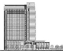
The Alfred A. Arraj United States Courthouse in Denver, Colorado serves as a model for designs that balances openness, security, and sustainability. The building showcases many sustainable strategies, including photovoltaic cells and daylighting using light shelves, while also being one of the first U.S. courthouses to meet the "GSA Security Design Criteria" standards.
It is important to understand that secure/safe, sustainable facilities don't just happen. The level of security/safety and sustainability incorporated in a facility varies greatly from project to project. But achieving quality, high performance facilities has a lot to do with an integrated process that identifies and embraces the goals of the project—including security/safety, sustainability, productivity, accessibility, functionality, aesthetics, historic preservation, and cost-effectiveness—early on. Working as a team from the outset, planners, designers, engineers, and all project stakeholders are able to develop creative solutions to design challenges that yield multiple benefits. For example, a massive, reinforced concrete wall can serve as blast protection for its occupants and a passive solar device saving energy during facility operation, resulting in a more secure, comfortable working environment. Also, rather than optimizing individual systems, the project team must understand that the most effective results can be obtained by designing various building systems and components as interdependent parts of the entire structure. This conceptual framework starts at the planning phase and is carried out through design and construction to building activation and operation. See also 'Whole Building' Approach and Aesthetics—Engage the Integrated Design Process.
Given budgetary and other constraints, integrating secure/safe and sustainable design objectives oftentimes requires compromise and tradeoffs. For example, increasing glazing area to provide daylighting can be incompatible with the desire to decrease glazing to minimize glass hazard. Similarly, designating surface parking away from a building to provide appropriate stand-off distance can limit the extent to which a project can meet its site disturbance reduction goals. These inherent conflicts challenge the project team to find creative solutions for the issues at hand.
Following are key areas of interaction between security/safety and sustainability goals and measures. The project team is advised to evaluate the benefits and disadvantages of pursuing these strategies, weighing them against the project's identified requirements and desired outcome in order to achieve a balanced design. Engaging integrated design will greatly facilitate this process.
With today's concern about climate change and emphasis on significantly reducing energy consumption while reducing greenhouse gas emissions and carbon, it is more important than ever to incorporate secure/safe and sustainable trade-offs and synergies into building projects.
Security and sustainable site planning strategies can significantly affect each other. For example, a facility's risk can be increased and security can be compromised by siting it in an urban area to protect greenfields and preserve habitat and natural resources; locating carpool/vanpool parking and bike racks nearby to promote alternative transportation; constructing under-building parking to minimize habitat disturbance; and installing covered walkways and landscaping to reduce heat islands and control erosion. On the other hand, security measures such as building setbacks, or standoff distances, to create protective building perimeters and to restrict access; installing barriers (e.g., bollards, reinforced planters, and site furnishings) to withstand assaults by moving vehicles; and locating parking areas in remote areas and/or eliminating under-building parking areas to minimize blast effects from potential vehicle bombs, usually result in increased development of open space, habitat disturbance, and possibly erosion.
Erosion Control Measures: The erosion of soil caused by precipitation or wind can lead to destruction of vegetation, degradation of property, and sedimentation of local water bodies as well as unstable building foundations and potential loss of structural integrity. Erosion control measures can be implemented to stabilize the soil (e.g., seeding and mulching, installing pervious paving) and/or to retain sediment after erosion had occurred (e.g., earth dikes and sediment basins). These help to reduce the negative impacts on water and air quality as well as mitigate potential damage to a building's foundation and structural system due to floods, mudslides, torrential rainstorms, and other natural hazards. For more information on erosion control measures, see WBDG Achieving Sustainable Site Design through Low Impact Development Practices and Low Impact Development Technologies.
Landscaping: Keeping sustainability and safety goals in mind, designers can create landscaping schemes that can at once reduce environmental impacts and deter crime. For example, landscaping elements such as retention ponds and berms can be used to control erosion, manage stormwater, and reduce heat islands while also serving as physical barriers to control access to a building and to deflect the effects of a blast. Native or climate tolerant trees and plants help to improve the quality of the site as well as provide protection by obscuring assets and people. Note, however, that trees, large bushes, and shrubs, can also screen perpetrators from view. Crime Prevention Through Environmental Design (CPTED) is a set of strategies that uses natural access control, natural surveillance, and territoriality and boundary definition to reduce the opportunities and fear of predatory stranger to stranger crime and improve the quality of life. Early coordination of sustainable site design with CPTED is critical to avoid conflicts between the two strategies. For more information on landscaping, see WBDG Sustainable—Optimize Site Potential; Achieving Sustainable Site Design through Low Impact Development Practices and Low Impact Development Technologies.

Blocking sightlines
Dry Fire Hydrants: One of the synergistic technologies for achieving water conservation and fire safety is a dry fire hydrant. Dry hydrants are non-pressurized suction pipe systems that are permanently installed in ponds or lakes and use the untreated water, instead of municipal water, to fight fires. Utilized in areas that lack conventional fire protection, areas that cannot handle the large volumes of water due to antiquated systems, or during peak use seasons when there is low water pressure, dry hydrants allow fire departments to be much more efficient by providing close water sources to fire risks. Since dry hydrants are installed below frost line and do not require electricity, they are capable of supplying water in the case of natural disasters such as hurricanes and tornadoes when electricity lines are knocked down, or during extreme cold or hot weather where conventional hydrant pipes can freeze or break. Also, dry fire hydrants help to save precious drinking water and conserve energy by using rainwater that does not need to be processed to be used for fighting fires. For more information, see The Dry Hydrant Concept .
Constructed Wetlands: Constructed wetlands, used for wastewater treatment, can be incorporated into perimeter protection strategies to control vehicular and pedestrian access. For more information on constructed wetlands, see WBDG Achieving Sustainable Site Design through Low Impact Development Practices and Low Impact Development Technologies.

Trombe wall at NREL's Solar Energy Research Facility—Golden, Colorado
Because the opportunity to reduce load and employ energy efficiency measures is dependent on the chosen project site and site design, a site planned for security may not be optimal for energy conservation. The installation of onsite power generation and fuel supply for back-up power and/or increased power reliability may increase noise and development of open space as well as habitat disturbance. Also, additional equipment and systems needed to mitigate natural hazards, protect against fires, and defend against terrorist attacks will increase the building's energy loads and may affect its energy performance. The roof of covered parking facilities could be used to mount photovoltaic modules to provide quiet onsite power, while eliminating the need to use additional open space for power generation.
Building Commissioning: Commissioning is the systematic process of ensuring and documenting that all building systems perform according to specification and design intent, consistent with the owner's operational needs. The goals of commissioning are to improve the building delivery process; to provide a safe and healthy facility; to improve energy performance; to reduce operating costs; to provide O&M staff orientation and training; and to improve systems documentation. According to the U.S. Green Building Council (USGBC), commissioning can improve new building energy performance by 8% to 30%. The more complex the building type and the more integrated the building systems, the more likely that a formal building commissioning process will prove valuable. Use commissioning to verify that the project's safety and sustainability goals have been achieved.
Integrated Building Automation and Control Systems (BAS): BAS integrates and automates traditionally stand-alone building automation and control systems such as HVAC, fire, lighting, and security systems into one comprehensive system. This enables electronic monitoring and control of air flow, space temperature, system performance, energy conservation, fire alarms, security functions, etc. from a single, centralized location for optimized building operations, energy efficiency, indoor comfort, safety, and security. For example, a BAS can be programmed such that a duct sensor can monitor the efficiency of the air flow, but can also detect a contaminant in the ductwork and alarm the facility manager who can then reconfigure the HVAC system in that part of the building, notify the proper officials, and evacuate occupants safely.
Renewable Distributed Energy Technologies: The use of renewable distributed energy technologies (e.g., wind turbines, photovoltaics, geothermal heat pump, and biomass gasifiers) reduces environmental impacts associated with utility energy production and use such as natural resources destruction, air pollution, and water pollution. They also offer consumers the potential for lower cost, higher service reliability, high power quality, increased energy efficiency, and energy security.
Thermal Mass Walls (Trombe Walls): Trombe walls are used to passively heat a space. A typical Trombe wall consists of an 8- to 16-inch thick masonry, stone, adobe, or concrete wall coated with a dark, heat-absorbing material and faced with a single or double layer of glass. The glass is placed from about 3/4" to 6" away from the wall to create a small airspace. Heat from sunlight passing through the glass is absorbed by the dark surface and stored in the wall. As it cools gradually during the night, it slowly releases its stored heat indirectly into the space. Trombe walls can serve double duty to reduce energy consumption and provide blast protection if they are integrated into the structural system and are made of reinforced concrete—masonry walls break up readily and become secondary fragments during blasts.
Window Films: Dangerous glass shards caused by natural hazards, accidents, or explosions can harm building occupants and visitors. Certain window films are designed to help hold shattered glass together, and make the glass stronger, and more resistant to breakage for improved safety and security. In addition, these films can reduce solar heat gain, glare, and fading for energy conservation and occupant comfort.
Buildings should be safe places to live and work. However, only a few buildings need to be Level 5 secure (critical to national security). To prevent unneeded security upgrades, hence use of more resources and materials, a comprehensive threat assessment, vulnerability assessment, and risk analysis must be conducted to identify the appropriate level of security for the building.
There are some security and safety products made of materials with recycled content or other environmentally preferable characteristics. Examples include reinforced concrete site furniture made with slag (a by-product of steel production) and recycled content metal fencing (both could be used for perimeter access control).
Glazing and Daylighting: Daylighting improves indoor environment of buildings by exposing occupants to natural light. This can result in improved worker productivity and reduced energy costs. While daylighting can also contribute to the security of a building by shedding light on otherwise dark corners, it does increase the potential for glass hazard caused by natural disasters, accidents, or blast events. Size and locate windows with detonation points in mind. Understanding that extensive damage to conventional glazing can still result since blast pressures will wrap around buildings. Where appropriate, specify blast resistant glazing or window film that can also reject heat and glare. Avoid exterior ornamentation, including certain sun control and shading devices, that can break away easily. Also, note that the placement of windows and doors to allow for good visibility and surveillance may interfere with daylighting schemes.
Natural Ventilation vs. Mechanical Ventilation: Natural ventilation has become an increasingly energy-efficient and attractive method for providing acceptable indoor air quality and maintaining a healthy, comfortable, and productive indoor climate rather than the more prevailing approach of using energy-intensive mechanical ventilation. Power sources are not needed to operate natural ventilation systems, so building occupants can maintain their level of comfort in the event of power shortages or blackouts. On the other hand, natural ventilation systems could bring outside contaminants inside. For critical and high-risk buildings, mechanical ventilation with special filters is recommended to protect against possible chemical, biological, and radiological (CBR) agents from entering interior spaces. Although more energy will be used, mechanical ventilation does allow for precise control of humidity, preventing the growth of mold and mildew. Under-floor air distribution systems should not be used in laboratories or other spaces containing hazardous materials that could spill onto the floor and contaminate the under-floor air.
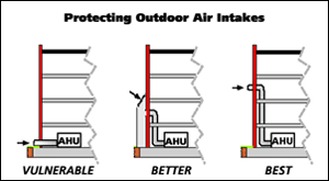
Protecting outdoor air intakes
Dedicated Ventilation and/or Exhaust Systems: Exposure of building occupants to potentially hazardous chemical, biological, and radiological (CBR) agents negatively impacts the indoor environment and can pose serious health threats. To help maintain superior indoor air quality and protect people's health, dedicated ventilation systems (aka. dedicated outdoor air systems [DOAS]) and dedicated exhaust systems can be installed. DOAS use separate air handlers to condition and deliver the minimum required constant volume of outdoor air. Be sure to protect all outdoor air intakes and locate discharge points away from them (see Figure to the right). For more information, see the Department of Health and Human Services / National Institute for Occupational Safety and Health publications Guidance for Protecting Building Environments from Airborne Chemical, Biological, or Radiological Attacks, May 2002 and Guidance for Filtration and Air-Cleaning Systems to Protect Building Environments from Airborne Chemical, Biological, or Radiological Attacks, April 2003.
Tight Building Envelope: In traditional construction, infiltration occurs through gaps and cracks in the building envelope. Excess infiltration of cold air in the winter and hot humid air during the summer can create uncomfortable indoor environments, including mold and mildew and raise heating and cooling costs by 20% to 40%. Such unintentional infiltration is also a concern for an exterior chemical, biological, and radiological (CBR) release at some distance from a building, such as a large-scale attack. Decreasing infiltration improves comfort, saves energy, controls moisture, reduces indoor pollution, and promotes ventilation. Also, tight building construction in combination with building pressurization can be an effective CBR-protection strategy.
The table below identifies sustainable design considerations and opportunities when employing various safe design strategies.
| Safety and Security Strategies | Sustainable Design Considerations/Opportunities |
|---|---|
| Access Control* | |
| Secure site perimeter | Integrate with sustainable landscaping scheme. See WBDG Sustainable—Optimize Site Potential and Achieving Sustainable Site Design through Low Impact Development Practices. |
| Use barriers to prevent passage of vehicles | Use natural and/or environmentally friendly barriers (e.g., trees, retention ponds, etc.). Use reinforced site furniture, planters, etc. as vehicle barriers. See WBDG Achieving Sustainable Site Design through Low Impact Development Practices and Low Impact Development Technologies. |
| Minimize public entrances into the building | Integrate with daylighting scheme. |
| Secure vulnerable openings (e.g. doors, first floor windows) | Integrate with daylighting scheme. |
| Install electronic access systems (e.g., parking, elevators) | Use energy-efficient systems. Consider renewable and/or distributed energy resources. See WBDG Building Integrated Photovoltaics, Distributed Energy Resources, Fuel Cell Technology, Microturbines. |
| Secure critical functions (e.g., IT, mechanical systems) | Consider dedicated ventilation and/or exhaust systems. |
| Surveillance* | |
| Locate windows and doors to allow for good visibility | Integrate with daylighting scheme. |
| Avoid spaces that permit concealment | Integrate with daylighting scheme. |
| Define public versus private interior zones | Use signage and other directional devices manufactured from recycled material. Use barriers with low-VOC or no VOC finishes. |
| Avoid blocking lines of sight with fencing and landscaping | Integrate with landscaping and daylighting schemes. |
| Locate public areas (e.g., restrooms) where they can be easily observed | Integrate with water and energy efficient restroom fixtures scheme. |
| Design lighting to reinforce natural surveillance | Integrate with building automation and control systems. Use energy-efficient systems. Consider renewable and/or distributed energy sources, such as solar power night lighting. See WBDG Building Integrated Photovoltaics, Distributed Energy Resources, Fuel Cell Technology, Microturbines. |
| Install intrusion devices and video systems | Integrate with building automation and control systems. Use energy-efficient lighting and controls. Use low-light or no-light cameras for scene observation that minimize/eliminate the need for electrical lighting. Consider renewable and/or distributed energy sources. |
| Use screen and tracking systems | Integrate with building automation and control systems. Use energy-efficient lighting. Consider renewable and/or distributed energy sources. |
| Blast Protection* | |
| Design structural systems to prevent or delay building collapse | Integrate with passive solar design (e.g., Trombe walls). Use sustainable materials (e.g., fly-ash concrete, slag concrete, steel columns, etc.). |
| Use building configurations to better resist blast shock waves | Integrate with passive solar design and daylighting scheme. |
| Maximize distances between parking and buildings | Integrate with alternative transportation plans. |
| Size and locate windows with detonation points in mind | Integrate with daylighting scheme. Specify glazing or window films that reduce heat gain and glare and provide blast protection. |
| Use blast or ballistic resistant glazing | Use blast or ballistic resistant window films that are also energy-efficient (reduce heat gain and glare). |
| Increase strength of exterior cladding and nonstructural elements | Use sustainable materials. Consider thermal benefits of strengthened cladding options. |
| Avoid exterior ornamentation that can break away | Integrate with sun control and shading devices. |
| Chemical, Biological, Radiological Protection*. | |
| Elevate fresh air intakes | Integrate with energy-efficient HVAC system. |
| Prevent unauthorized access to fresh-air intakes | Specify bars and grates to be manufactured with recycled steel. |
| Reduce need for utilities | Consider renewable such as daylighting, passive solar heating, photovoltaics, and geothermal; and/or distributed energy resources. |
| Apply external air filtration and overpressurization techniques | Integrate with building automation and control systems. |
| Use internal air filtration technologies | Integrate with building automation and control systems. |
| Secure vulnerable areas (e.g., mail rooms, loading docks, mechanical rooms, storage) | Consider dedicated ventilation and/or exhaust systems. |
| Establish mail-handling protocols and procedures | Utilize energy efficient equipment, machinery, and lighting. |
| Establish emergency plans for biochemical attacks | Consider dedicated ventilation and/or exhaust systems. |
| Energy Security* | |
| Create redundant systems | Reduce energy loads. Use energy-efficient systems. Consider renewable and/or distributed energy resources. |
| Occupant Safety and Health** | |
| Provide designs that eliminate or reduce hazards in the work place to prevent mishaps | Integrate safety mechanisms with sustainable features. Use integrated building automation and control systems. |
| Prevent occupational injuries and illnesses | Consider integrated natural and mechanical ventilation systems. Use integrated building automation and control systems. |
| Prevent falls from heights | Use sustainable materials for guardrails and barriers. Operable windows should have safety measures to prevent falls. |
| Prevent slips, trips, and falls | Integrate daylighting into illumination scheme. Use LED lamps and fixtures. Use electroluminescent devices which require no source of electricity. |
| Ensure electrical safety | Follow standards and recommended practices for installing and operating photovoltaic systems and distributed energy resources, such as fuel cells and microturbines. |
| Eliminate exposure to hazardous materials (e.g., volatile organic compounds (VOCs) and formaldehyde, lead, and asbestos in older buildings) | Use sustainable materials (e.g., no-VOC paints, adhesives, and sealants, formaldehyde-free finish panels, etc.). Use dedicated ventilation and/or exhaust systems in copy rooms, labs, loading docks, and mailrooms. |
| Provide good indoor air quality (IAQ) and adequate ventilation | Use daylighting. Consider integrated natural and mechanical ventilation systems. Use integrated building automation and control systems. |
| Provide ergonomic work places to prevent work-related musculoskeletal disorders (WMSD) | Use sustainable materials, including furnishings with recycled content, recyclable or compostable materials, and reconditioned furniture. |
| Perform proper building operations and maintenance | Implement total building commissioning. Use integrated building automation and control systems. |
| Provide for proper receiving, storing, and handling of consumable materials | Implement total building commissioning. |
* Source: Building Security Through Design: A Primer for Architects, Design Professionals, and their Clients by The American Institute of Architects. Washington, DC: AIA, p. 15. ** Source: WBDG Safe—Ensure Occupant Safety & Health

California's Office of Emergency Services Headquarters—Sacramento, California. Photo Credit: enr.com and archrecord.construction.com
California's Office of Emergency Services Headquarters, Sacramento, California: Located on a 12-acre site, the complex is the anchor project for the adaptive reuse of the former Mather Air Force Base. It exemplifies the newest generation of open yet secure, safe, and sustainable buildings. Strategies and features include: use of landform to control vehicular access; open, daylit spaces for comfortable, productive work environments; and back-up fuel supply for energy security.
Pictured on right: Break out rooms surround the command and logistics room, shielding it from exposure to the outside, although clerestories allow a generous amount of daylight to enter the space.
Williams Communications' Headquarters, Tulsa, Oklahoma: At the core of the Williams Communications' headquarters building is a 47,000 sf highly secure network operations center that provides a spacious, daylit, dynamic work environment for its occupants.
Defense Intelligence Analysis Center (DIAC), Bolling Air Force Base, Washington, DC: The approximately $100 million project is a first-class, six story 450,000 sf office building designed to consolidate uniquely skilled intelligence personnel currently working in lease spaces throughout the region. Connected to an existing building via a corridor, the project successfully integrates security and sustainability features within the design, creating an energy-efficient, comfortable, yet very secure facility. For example, the design of the facility takes advantage of the earth berm behind so it would be able to withstand impact by a truck traveling at 40 MPH.

Pentagon renovations
Pentagon Renovation, Arlington, Virginia: The energy management control system installed to efficiently manage the heating, cooling, and lighting systems throughout the Pentagon allowed officials to manipulate all the building systems in the first minutes after the 9/11 terrorist attack. This minimized the areas of the building that had to be entered to operate equipment, reducing risks to employees. Also, the Pentagon's new windows, installed for security and energy efficiency benefits, helped to contain damage from the attack.
Oklahoma City Federal Building, Oklahoma City, Oklahoma: The 181,000sf facility replaced the Alfred P. Murrah Federal Office Building, which was destroyed by a bomb in 1995. As the owner, the U.S. General Services Administration (GSA) wanted the building to be transparent, open, and accessible to public as well as secure and sustainable. One of the primary strategies was using landscaping, including light fixtures and other streetscape items, to provide the appropriate setback distance and to serve as security barriers. For more information, see "Secure and Sustainable" by Gordon Wright. Building Design and Construction.
This supplement to ABAAS tailors some of the requirements to better meet the barrier free needs of the Department of Veterans Affairs (VA) in its facilities.
Previous requirements have been simplified and abbreviated so that these six pages replace the former 26-page VA Barrier Free Design Handbook (H-08-13).
To provide both architectural programming and interior design guidance for improvement projects in base theaters.
This document addresses planning, design and construction criteria guidance for Beale Air Force Base (AFB) so that implementing Sustainable Development and High Performance Green Building Design (SD&HPGBD) objectives become a primary consideration, along with building site, context, program needs, and function.
Due to expanding requirements and diminishing resources, and lacking holistic/intergrated design approaches, HQ ACC/A7PS has formulated a process for measuring sustainability at Air Combat Command (ACC) installations. This process will establish baseline metrics to identify actionable opportunities and investment strategies, and facilitate yea-to-year comparisons. There are many individual efforts already in place at HQ ACC/A7PS and at the installation level.
Many buildings constructed today extend one or several floors below grade level. These below grade areas provide functional spaces for uses such as storage, office space, mechanical/electrical rooms, parking, tunnels, crawlspaces, etc. While below grade areas in buildings provide important critical functions for the building, the subject of below grade building enclosure systems, although widely addressed during construction practices is not always wholly understood. The below grade portion of the building enclosure is seldom analyzed numerically in design. Acceptance of poor performance of the below grade building enclosure is typical and historically not questioned. Leaking into basement areas is a common problem for building operators and managers. Air quality, such as radon, and conditioning in terms of humidity levels are often a concern.
Durability of design and materials is mandatory with below grade enclosure systems. Unlike some other building components that might be designed to be replaced several times within the overall building service life, below grade systems need to be built to approximate overall service life. Below grade systems are often inaccessible for repairs and extremely costly if repairs or modifications are necessary. For below grade enclosure systems design and materials must not focus on the first initial cost but consider the life cycle costs of various design options, especially costs to repair or replace systems that are buried.
Buildings frequently have plazas, vaults, tunnels or extensions below grade. The planning, development, detailing and construction of waterproofing for such features are significant. Although much more complex and far more maintenance intensive, these features are generally not treated with the same detailing attention that roof assemblies receive. Protection, drainage and isolation along with thermal considerations must be incorporated into the design. Requirements for overhead waterproofing in tunnels or building obtrusions are significant and need to be treated accordingly. Design of plaza surfaces, green-scape and tree or soil planter features, above the buried element also requires special design consideration.
Over the past two decades, plazas and special use features (fountains, planters and even athletic function) have become a more common and complex element in structure design. Tunnels and vaults, although a historic feature, are also experiencing increased design demand as they are upgraded to higher levels of service to accommodate utilities, mechanical services or signal and communication conduits.
Plaza decks, tunnels and vaults are subject to some of the most accelerated and vigorous deterioration and distress of any structural system. Harsh exposure conditions from exposure, moisture, thermal effects, weathering, and traffic often reduce these systems serviceability at a rate even surpassing that of parking and bridge deck slabs. Accordingly, special analysis of plazas, tunnels and vaults aesthetic, wearing, moisture protection and isolation, and structural support systems, should be performed.
Plaza systems generally disintegrate and become unserviceable for three reasons:
Other common causes of plaza deterioration or failure are: severe exposure (including freeze thaw), chemical applications, overload, and/or improper materials selection and application.
The design of tunnels and vaults, although not specifically discussed, is similar to the design of plaza decks, foundation walls, and slabs on grade which are discussed below and in the related sections.
Readers are advised to obtain expert advice when designing systems which are below the water table or which are enclosing particularly vulnerable occupancies. Expert advice may also be necessary when dealing with field conditions.
These Design Guide sections describe the basic components of below grade enclosure systems and categorize its functions, provide guidelines for design considerations, and provide details for adaptation for actual building projects. The scope of these sections is limited to the enclosure elements of the below grade portion of the building and does not consider interior elements. Below grade enclosures are typically comprised of three main elements:
For each of the three elements the following items are discussed:
Figure 1 graphically illustrates the three main elements and the typical loadings for below grade building enclosure systems.
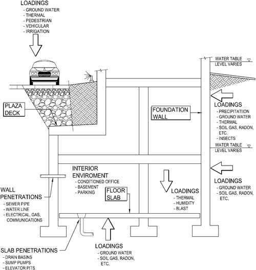
Fig. 1. Below Grade Building Systems Schematic
As with other building enclosure systems the functions of each of the elements of the below grade building enclosure can be grouped into four categories, as follows:
Structural Support Functions—to support, resist, transfer and otherwise accommodate all the structural forms of loading imposed by the interior and exterior environments, by the enclosure and by the building itself. The below grade enclosure is often part of the buildings superstructure.
Environmental Control Functions—to control, regulate and/or moderate all the loadings due to the separation of the interior and exterior environments; largely the flow of mass (air, moisture, etc.) and energy (heat, sound, etc.).
Finish Functions—to finish the enclosure surfaces—the interfaces of the enclosure with the interior and exterior environments. Each of the two interfaces must meet the relevant visual, aesthetic, wear and other requirements.
Distribution Functions—to distribute services or utilities such as power, communication, security, water in its forms, gas, and air conditioned air to, from and within the enclosure itself.
The four function categories, i.e. Structural Support, Environmental Control, Finish and Distribution, are expanded in general terms for each of the three elements of below grade enclosures.
The success of below grade building enclosure systems is largely dependent on the ability to control moisture. The control of moisture can only be achieved with proper investigation, design and construction practices. Also of importance is to understand where problems are likely to occur. Kubal suggests the following principle:
"The 90% / 1% Principle: As much as 90 percent of all water intrusion problems occur within 1 percent of the total building or structure exterior surface area."
Therefore, attention to detail, particularly at penetrations and termination (connections to adjacent elements) is critical to the performance of below grade enclosure systems. Kubal suggests another principle that is equally important:
"The 99% Principle: Approximately 99 percent of waterproofing leaks are attributable to causes other than material or system failures."
Failures typically occur from improper design or construction practices not material failure itself. Putting these two principles together Kubal states:
"By considering these two principles together, it can be expected that 1 percent of a building's exterior area will typically involve actual and direct leakage and that the cause will have a 99 percent chance of being anything but material failure."
The success of waterproofing systems is very dependent on applicator skill and attention to detail. Recognizing that the performance of below grade building systems relies so heavily on design and construction aspects, it is critical to discuss the overall design and construction process.
The process can be divided into three (3) phases:
Troubleshooting following construction when leakage occurs is also considered as a closing section of this guideline.
Through rigorous application of the criteria and design features presented the overall performance requirements of the system for characteristics including moisture, thermal, air quality, fire safety, and acoustics can be determined.
A waterproofing assembly should be designed after a number of criteria have been carefully considered, including:
These criteria play important roles in the ultimate success or failure of a waterproofing assembly and should be considered by a designer to determine the appropriate components of a waterproofing assembly, applicable products and specifications, and construction details to be used.
In addition, a designer should be certain requirements of waterproofing material manufacturers, applicable insurance underwriters, and building codes and/or other regulatory agencies are taken into account. It is recommended that material manufacturers' published specifications and details be consulted during the design of a waterproofing assembly.
The investigation phase deals primarily with determining the site conditions prior to the design development. For virtually all construction projects, soil specimens are taken that provide basic information concerning soil conditions. These soil conditions once combined with water table information can identify the ground water characteristics in the vicinity of the site. It is these ground water characteristics taken as a benchmark that govern and contribute heavily to the success or failure of the below grade building enclosure system design.
Interpretation of site boring (and other site related) information should be made considering of the time of year borings were taken. For example, evaluating soil-boring conditions with respect to ground water could produce one result if samples were extracted during the spring months and under conditions of heavy rain or run-off from snowmelt. Similar samples taken at a later time in the year such as August or September following a dry season could result in different ground water conditions. Consult with a qualified geotechnical engineer to provide interpretation of soils investigations and recommendations for waterproofing systems.
Site work should also consider the conditions in the vicinity associated with surface characteristics; drainage slope, permeability, and other utilities or other features. Underground storage tanks, sewer lines, reservoirs, water ways or water shed paths need all be examined when considering the overall site conditions.
Structure Use Requirements—Following the site assessment, the structure use requirements concerning the need for absolute dryness or hundred (100%) percent waterproofing should be considered. Structures have variable demand for underground services. Structure utilization is a significant element of the original investigation process and should be fully considered during development of the criteria for moisture capture, moisture capture and overall water management system that affect waterproofing system design and selection.
Following the assessment of usage, a system for subsurface water management should be examined. There are both internal water management techniques, such as sump pumps or dewatering systems in the basement, or external foundation drains that all need to be coordinated to achieve effective water management at the time of design. Once again, the requirements for specific needs and features of the building basement and sub-basement system must be fully considered in order to achieve the desired result.
The design of the waterproofing system must follow the selected structural design system. Until the structural system is selected and certain features of the design established, it is not practical to develop an effective waterproofing system or water management system other than at a conceptual level. The sub-chapters on foundation walls, slabs-on-grade, and decks/plazas/tunnels/vaults provide information on waterproofing systems under the topic, "Environmental Control Functions." This document develops the concepts, principals and standards as opposed to specific detailing for each condition. Common details are provided for features of water management, waterproofing protection and the basics of system installation. Sound engineering judgment and expertise is needed to apply these guidelines and procedures to a particular project.
Clear definition of the penetrations required in the structural wall or floor system must be established. Detailing of these penetrations to make them water tight under all conditions of use are paramount to the success of below grade enclosure systems.
Proper specifications to address the various issues associated with water management should be done consistent with the typical specifications format. Where special requirements occur to amplify or highlight certain needs for the structure in question, special notations or supplemental specifications should be drafted that address the waterproofing system characteristics and particulars. Such specifications are typically accompanied by detailing of the various aspects of the waterproofing installation. This detailing once established in concept and for intent for specification requirements (prescription vs. performance) can be supplemented by manufacturer details addressing the particulars of a given waterproofing system. These details commonly deal with such things as penetrations, joints, drains, sumps and moisture collection systems.
Adequate construction administration involving the review of material submittals and installation sequences are important to performance, as is on site observation by the design professional to verify that the construction is being completed in general accordance with the construction documents. A well planned design improperly implemented will not provide adequate performance.
With the construction process underway, steps must be taken to properly coordinate the waterproofing applications or waterproofing requirements with the general contractor's scheduling. It is frequently the case that schedules are compressed and the needs of waterproofing exterior walls once satisfactorily curing is achieved can produce kamikaze type efforts with respect to exterior wall waterproofing. The conditions under which waterproofing must be installed in order to be effective and meet the manufacturer specification for warranty must be clearly spelled out. Exterior wall drainage application and subdrain discharge must be complete at this time.
Coordination meetings at the time of construction that include the waterproofing subcontractor, waterproofing material manufacturer, and any sub-trades should also be identified and coordinated. Features and characteristics of each installation and system should be examined closely.
Care should be taken to inspect the substrate surfaces for the anticipated waterproofing to ensure that all deleterious materials, stains, coatings, previous waterproofing, concrete flaws such as honeycomb or fins or splatters or tie remnants are removed completely to the satisfaction of the waterproofing Manufacturer.
The substrate surfaces should be dry and cured according to the waterproofing manufacturer's specifications prior to waterproofing application, or until Manufacturer is satisfied by various moisture test methods, such as a poly barrier condensation test. Finally, an adhesion pull test should be administered to the initial application of waterproofing to verify the bond to the substrate.
Troubleshooting of the system at the time of installation of waterproofing systems and performed in an integrity test at the completion of the waterproofing installation should be considered. See the Resource Page on Integrity Testing. A special interest for water testing or troubleshooting before the fact relates to overhead structures that must retain water but will be subsequently buried or backfilled following construction. All aspects of troubleshooting at the time of construction should be considered.
The following details can be downloaded in DWG format or viewed online in DWF™ (Design Web Format™) or Adobe Acrobat PDF.
Details related to below grade building enclosure systems with commentary can be found in the following sections:
The following are emerging issues in below grade building enclosure systems:
Conform to local codes and ordinances with regard to groundwater situations except where provisions provided in this document are more stringent or complete.
See appropriate sections under applicable guide specifications: Unified Facility Guide Specifications (UFGS), VA Guide Specifications, Federal Guide for Green Construction Specifications, MasterSpec®
NOTE: Photographs, figures, and drawings were provided by the original author unless otherwise noted.
Building Name: Bertschi School Living Science Building Bulding Location: Seattle, Washington, United States Project Size (ft2, m2): 1,425 ft2 Building Type: Educational Project Type: New Construction/Addition Delivery Method: Integrated Project Delivery (IPD) Total Building Costs: $935,000 Construction (All design services pro-bono) Owner: Bertschi School
This resource page describes overall best practices to achieve compliance with accessibility regulations through the entire project cycle, including concept design through construction completion. Employing these best practices will help enhance compliance with applicable federal laws, including the Architectural Barriers Act (ABA) of 1968, the Americans with Disabilities Act of 1990, as amended (ADA), Section 504 of the Rehabilitation Act of 1973, or the Fair Housing Amendments Act of 1988 (FHA).
Accessibility is the responsibility of everyone involved in the project, including but not limited to the owner, designers, architects, engineers, builders, and contractors. Best practices to ensure compliance include identifying accessibility compliance as a key goal at the onset of a project. Reinforcing the focus on accessibility compliance during the "kick-off" meeting is a method of gaining buy-in from all project team members. The kick-off meeting is also a venue for setting expectations, roles, and responsibilities and ensuring that everyone understands the importance their function plays in the overall compliance plan. In addition, providing accessibility training which specifically relates to the project can help set design and construction teams up for success.
Plan review can be conducted at various stages of the project-cycle to ensure that full compliance with applicable accessibility laws and codes is achieved. Through plan review, instances of non-compliance will be highlighted due to unaccounted finishes, incomplete and non-compliant schedules and specs, inaccurate details, etc. Qualified accessibility experts will be able to provide detailed reports that identify potential violations along with recommendations on how to address common oversights. Conducting plan reviews as a best practice allows time to get interpretations and variances that will help the project translate from plans to practice effectively.
Day-to-day project oversight performed by construction supervisors and project managers knowledgeable in accessibility requirements can help to achieve compliance. Know that deviations from the plans can affect compliance and oversights can be costly and difficult to fix after construction begins. In addition, be mindful of change orders, value engineering, and improper installation of finishes, which can all impact compliance. Lastly, correct interpretation of construction documents is essential to achieving compliance; always ask questions before you build to be sure you understand the plans thoroughly.
This section highlights tools that help make it easier for designers, developers, and contractors to assess facilities for accessibility compliance. While several of the tools are intended for new construction or alteration projects, they can also be used to survey existing buildings to identify those features or elements in need of modifications.
Conducting site inspections at various stages of new construction and alteration will ensure compliance with applicable accessibility laws and codes. Construction teams, local code inspectors, and/or accessibility experts can all conduct site inspections to identify potential issues of non-compliance and provide recommendations for addressing common oversights. It is best not to wait until the project is near completion to conduct an assessment, as changes are costly and difficult to make during finishing stages.
Checklists used as a guide for conducting surveys of existing facilities to help identify non-compliance with applicable accessible design and construction requirements can be useful. However, many commercially available checklists do not include accurate and updated information and can be misleading. Be sure to use a checklist available from a trusted source to best inform the survey process. New tools and processes including accessibility apps and the use of iPads in the field are a growing trend.
The most efficient tool used to measure the slope of a ground or floor surface is the digital level, also known as a digital inclinometer. A 24—inch long digital level is recommended because it is close to the width of a standard wheelchair. The digital level can be set to measure percent slope, degrees, or pitch (inches of rise per foot of run). Measuring percent slope is all that is needed to determine whether the running or cross slope of a surface is compliant with the maximum percent slope permitted. To maintain consistency of measurements, it is important to ensure that the level readout is always set to percent slope. Be sure to calibrate the level according to manufacturer's instructions; once calibrated, place it on the ground or floor surface—it automatically displays the percent slope.

The force required to open doors must be minimal so that they can be easily operated by those who might have limited upper body strength (such as the elderly), challenges with manual dexterity, or any other issue that might make opening heavy doors a challenge. Today, using a door pressure gauge is an efficient tool to assess compliance with requirements for opening force. To assess door pressure, open the door minimally; then, put the tip of the gauge against the door and use it to push the door open. The readout on the gauge will indicate the force required to open the door. The door pressure gauge can determine if the force required to open a door is greater than that permitted.
The major resource for guidance on accessible design is the U.S. Access Board (Access Board). The Access Board is an independent federal agency devoted to accessibility for people with disabilities. Key responsibilities of the Board include developing and maintaining accessibility requirements for the built environment, transit vehicles, telecommunications equipment, and electronic and information technology; providing technical assistance and training on these guidelines; and enforcing accessibility standards for federally funded facilities. For additional resources, see the Access Board's pages on Training & Webinars along with Research. In addition, the Access Board has developed explanatory Animations and Guides to the ADA Standards.
This guide provides an overview of best practices for energy-efficient data center design which spans the categories of Information Technology (IT) systems and their environmental conditions, data center air management, cooling and electrical systems, on-site generation, and heat recovery. IT system energy efficiency and environmental conditions are presented first because measures taken in these areas have a cascading effect of secondary energy savings for the mechanical and electrical systems. This guide concludes with a section on metrics and benchmarking values by which a data center and its systems energy efficiency can be evaluated. No design guide can offer ‘the most energy-efficient’ data center design but the guidelines that follow offer suggestions that provide efficiency benefits for a wide variety of data center scenarios.
This series includes the documents below. Download each file individually on the Collateral Equipment (FF&E) Criteria & Templates homepage.
Accessibility laws like the Architectural Barriers Act (1968), Section 504 of The Rehabilitation Act of 1973, the Fair Housing Act Amendments (1988), and the Americans with Disabilities Act (1990) establish minimum requirements that protect people with disabilities from discrimination in the built environment. Ron Mace, FAIA and Ruth Hall Lusher, saw the need to reevaluate using legal mandates to ensure usability by people with disabilities based on their experience with accessibility laws. Universal Design, the term for this revised approach, was based on the premise that the environment could be much more accessible than the minimum requirements of law required if designers focused attention on improving function for a large range of people.
At the broadest level, Universal Design is concerned with designing for diversity and equity.
Universal Design (UD) is also called inclusive design, design for all, or life span design. As initially conceived, UD was focused on usability issues. "The design of products and environments to be usable by all people, to the greatest extent possible, without the need for adaptation or specialized design" (Mace, 1985).
In the last ten years, the emphasis was broadened to wider issues of social inclusion. A newer definition is more relevant to all citizens without ignoring people with disabilities. It states that Universal Design is, "a process that enables and empowers a diverse population by improving human performance, health and wellness, and social participation" (Steinfeld and Maisel, 2012). In short, Universal Design makes life easier, healthier, and friendlier for all.
Universal Design increases the potential for developing a better quality of life for a wide range of individuals. It also reduces stigma by putting people with disabilities on an equal playing field. While it does not substitute for assistive technology, Universal Design benefits people with functional limitations and society as a whole. It supports people in being more self-reliant and socially engaged. For businesses and government, it reduces the economic burden of special programs and services designed to assist individual citizens, clients, or customers.
Proponents of Universal Design must recognize that products and environments can never be fully usable by every person in the world, but that services, management practices, and policies can benefit from Universal Design thinking. Universal Design should therefore be considered a process rather than an end state. There is never any end to the quest for improved usability, health, or social participation, so attention to more than just the built environment is needed to achieve these three broad outcomes.
Examples of UD features in buildings include automated doors, which provide an entrance for people of all abilities; integrated furniture components and power and communication systems that make outlets more convenient; and multi-sensory interactive wayfinding models that enable almost any person to comfortably operate and learn from a public map and directory system.
The following table provides some examples of the differences between Universal Design and accessible design.
| Universal | Accessible |
|---|---|
| A universally designed home plan costs the same as any other plan to build that anyone can purchase | A custom designed home based on an existing plan but requires additional costs for the redesign and custom construction details |
| Home improvement services that incorporate Universal Design as a basic service | Home modifications services by a contractor who charges more for her specialized knowledge of design for disability and aging |
| Automobile instruments and controls customizable to accommodate differences in perceptual abilities, stature, motor abilities, and preferences | Assistive technology used to adapt an automobile display for people with special needs |
| A no step building entry that everyone can use easily and together | A building entry with a ramp at the side that is out of the way for all visitors but is accessible by code |
| A hotel that has 100% universally designed rooms in a variety of types | A hotel that has only the code-required percentage of accessible rooms |
(Steinfeld and Maisel, 2012, p. 69)
The "Principles of Universal Design" were developed by a team of U.S. experts organized by the Center on Universal Design at NC State University in the 1990's. Accompanied by a set of guidelines for each Principle, they were a valuable tool for clarifying Universal Design for early adopters.
The Principles of Universal Design:
The eight Goals of Universal Design were developed in an effort to update the Principles, clarify the concept of Universal Design, incorporate human performance, health and wellness, and social participation as outcomes, and address contextual and cultural issues. For example, there are many sources of contextual differences, such as topography, economic development levels, cultural norms, and local values, which influence the way designers implement Universal Design. Increasingly, high value is placed on preserving cultural resources like historic buildings and natural resources. Attempts to enhance accessibility, however, often conflict with these two goals. Universal Design must address this conflict to overcome perceptions that it gets in the way of reaching other important design goals.
One barrier to adoption of Universal Design in middle- and low-income countries is the perception that it is often perceived as idealistic, expensive, or an imposition of Western values. It is realistic and appropriate to acknowledge that design strategies will differ or be adapted in different places and by different cultures. In some places, achieving the level of accessibility required by Western norms could be counterproductive. Thus, it is important that Universal Design strategies also address cultural values associated with social, economic, and physical context. In addition to addressing these concerns, the eight Goals of Universal Design were also conceived to link Universal Design to bodies of knowledge and identify measurable outcomes.
(Steinfeld and Maisel, 2012)
Universal Design has not been adopted as extensively within the design community as some other recent design movements (e.g., sustainability, historic preservation). One challenge facing adoption is a continued perception of Universal Design as design for disability. To reach professionals, continuing education and the development of communities of practice, especially among educators, is a priority.
In addition, just as Leadership in Energy and Environmental Design (LEED) guidelines and a certification program were created in response to a population with greater demands for conservation of energy and material resources, a set of UD guidelines was needed for designers to adequately respond to an increasingly diverse population. The innovative solutions for Universal Design (isUD) program launched in 2018. Developed by a multidisciplinary group of UD experts, isUD contains more than 500 UD solutions related to commercial buildings, to help development teams achieve the Goals of Universal Design. isUD facilitates integrating UD at all stages of a project-from the design process to policies and practices (see thisisUD.com). The tool provides a step-by-step checklist for project teams to use in their quest for ongoing inclusivity. Design projects that utilize a sufficient number of solutions and submit appropriate documentation are eligible for isUD certification. While voluntary, isUD provides a comprehensive evidence-based approach to design that exceeds the minimum requirements of accessibility regulations, and is the only available tool to systematically evaluate UD in buildings.
As a result of UD's growing popularity, many new issues have captured the attention of design professionals and their colleagues in related professions. Those issues with a close relationship to Universal Design include aging in place, sustainability, workplace design, public spaces, and social justice. Universal Design has much to contribute to solving any social problem in which usability and social participation play a major role in design response.
Aging in Place: A large majority of individuals want to age where they currently live. Aging in place offers numerous social and financial benefits, and promotes keys to successful aging such as life satisfaction, health, and self-esteem. A 2021 AARP survey indicates about three-quarters of those 50+ would like to stay in their current homes or communities for as long as possible, compared to about half of those ages 18–49 who feel the same. In order to remain in their homes, 34% of older respondents recognize they may need to make physical changes to their house.
To remain in their own homes while aging, people need housing designs that can be adapted to wider range of health conditions than traditional designs allow. Encouraging housing producers to adopt Universal Design features is a key aspect of design for aging in place. This includes a no-step entry, bathrooms on an accessible floor level, potential for a sleeping space on an accessible level, good lighting, efficient space planning, and other features that reduce effort and accommodate short-term and chronic disabilities.
Common Aging-in-Place Features:
(Steinfeld and White, 2010).
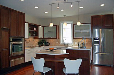
This image from the LIFEhouse™ shows many levels of lighting, multiple work center levels, and fixtures and appliances with Universal Design features. The home was the recipient of a National Association of Home Builders Gold Award for Best Universally Designed Home.
Sustainability: Sustainable products used in buildings need to be designed to be operable by people with limited function in order to comply with accessibility laws, but they also have to be usable for the broader population or they will not be effective in practice. Due to their novelty, they often present usability issues to end users. This can result in replacing the product and even abandoning the goal of sustainability. Acceptance of innovative sustainable products can be enhanced through Universal Design. Consider the example of a waterless urinal. Every men's restroom requires at least one lower urinal. Most waterless urinals are only designed for the higher, traditional position, which means that they may cause maintenance problems or even require an accessible, traditional water operated urinal to supplement the waterless unit. Some require special cleansers to protect the finish and special tools and procedures to change the trap. If not properly maintained, the urinal will cease to function, start emitting an odor, and anger building occupants and owners. Bad experiences like this can result in replacing the product and even abandoning the goal of sustainability.
Workplace: Universal Design is a critical consideration when designing workplace environments. Typically, adults spend a significant time working, thus making work environments important spaces in daily life (Sanford, 2012). People with disabilities, however, report being employed less than half as much as their non-disabled counterparts (Houtenville and Boege, 2020). The need for more accommodating work environments is gaining attention as the prevalence of disability and older adults in the workforce increases (Shore, Cleveland, and Sanchez, 2018; Taylor, 2018; Vespa, Armstrong, and Medina, 2018), and as work organizations increasingly strive to remove barriers to full participation of traditionally excluded groups such as racial, ethnic, and religious minorities, women, and, members of gender and sexual orientation minorities (Barak, 2016). With this growing diversity, organizational leaders have increasingly become aware of the importance of creating inclusive work environments (Nishii and Rich, 2014). Good design of the workplace can help increase participation of people with disabilities in the workforce, and can help to ensure that fewer accommodations will be needed if an employee has a disability. Additionally, achieving the highest level of usability in the workplace environment increases overall task efficiency, productivity, employee morale, and general safety, and also helps employers attract and keep a broad and diverse work force.
Common Workplace Features:

Provide workplace options (e.g., standing workstations) that enable employees to periodically get relief from the stress of standing or sitting for long periods of time, and work in an environment that is most productive for them.
Provide employees with access to environmental controls and light switches to allow them to adjust the temperature and light levels to best fit the requirements for their specific tasks, individual abilities, and preferences.
Public Spaces: Public spaces include facilities open to the public such as stores, restaurants, amusement parks, parks, and other recreation facilities, street rights-of-way, and transportation systems. Public accommodations are a critical domain for Universal Design because they are the site of key participation activities, including engagement in civic affairs, employment, recreation, education, and community mobility.
Common Universal Design Features in Public Spaces:

A tactile guide path in a museum helps all visitors find the information desk.


A store entrance with automated doors allows all customers to enter the same way.
Clear walkways, expanded corners, safety islands, and bike lanes enhance pedestrian, bicyclist, and driver safety.
Social Justice: Throughout the world, designers with a sense of social responsibility are concerned that good design, like many other resources of society, is a commodity that many cannot afford. Although initially focused on disability rights, Universal Design can focus on any civil rights issue because ultimately design for diversity is concerned with social justice for all. Thus, Universal Design should give attention to supporting access to housing, education, healthcare, transportation, and other resources in society for all those groups that have been excluded from full participation. Universal Design is particularly appropriate in the context of design for low-income minority groups, which often have higher rates of disability than the general population.

Hippo Water Roller. This design, inspired by a lawn roller, reduces the need for lifting and carrying and allows an individual to carry more water at one time (hipporoller.org)
American Association of Retired Persons (AARP)—A nonprofit membership organization dedicated to addressing the needs and interests of persons 50 and older. Through information and education, advocacy and service, AARP enhances the quality of life for all by promoting independence, dignity, and purpose. Among other things, AARP seeks to promote independent living and aging-in-place.
Center for Inclusive Design and Environmental Access (IDEA)—School of Architecture and Planning, University at Buffalo, Buffalo, NY—The Center engages in research and design focused on advancing equity and inclusion. It strives to improve the design of environments and products by creating person-centered tools, programs, and environments, and sharing these practices with change makers in universities, organizations, and communities.
Center for Inclusive Design and Innovation (CIDI)—The CIDI is dedicated to an inclusive society through innovations in assistive and universally designed technologies, with a goal of addressing the full range of needs for accessibility. CIDI is committed to the promotion of technological innovation and development of user-centered research, products, and services for individuals with disabilities.
Design for All Foundation—The Design for All Foundation is an international foundation that strives to develop, promote, research and disseminate Design for All among companies and organizations both at the public and private level, administrations, educational agents and also designers and professionals who intervene with the environment, products and services.
The United States Department of Veterans Affairs (VA) is committed to utilizing Building Information Modeling (BIM) tools, 3D Models, 2D Drawings, Data, and other uses to support the delivery and management of world-class healthcare for our nation’s veterans. The goal of VA’s use of BIM for new facilities is to deliver higher value in quality, timeliness, cost, and to maximize building performance during operations. VA recognizes BIM is not a specific software platform but rather an innovative process that encompasses the use of various software and techniques.
BIM Manual Appendix 2 - Maintaining Coding for 2D PRC - Deleted 11-01-2023
THIS PAGE SUPPORTED BY THE
Biogas is the gas produced by the biological breakdown of organic materials. Fermentation, or anaerobic digestion, is the most common process that breaks down the organic materials. The organic materials are then oxidized and create energy, which dates back to ancient Persians who observed that rotting vegetables produce flammable gas. Anaerobic digestion is a process that uses microorganisms to break down the organic material in the absence of oxygen, which creates energy. An anaerobic digestion plant was built to process sewage in Bombay in 1859, and has been used in the United Kingdom since 1895.
The types of organic materials include biomass, landfill waste, sewage, manure, and plant material. The most common gases produced are methane and carbon dioxide. Other common gases that can be formed include hydrogen, nitrogen, and carbon monoxide. Methane, hydrogen, and carbon monoxide can be combusted to create heat and electricity. When biogas is created from existing waste streams, it reduces odors and methane emissions and creates two renewable resources. Sewage sludge and animal slurries usually end up as fertilizer, so it is better to obtain fuel from them first, while preventing runoff and methane emissions at the same time. Biogas is not a widely used renewable energy technology for most new construction or major renovation projects since most buildings do not have a large source of organic material. However, projects located near a landfill or contained animal feeding operation may want to consider this option since it can provide low-cost energy.
Methane is a very potent greenhouse gas—more than 21 times stronger than carbon dioxide—and is a key contributor to global climate change. The U.S. Environmental Protection Agency (EPA) Landfill Methane Outreach Program estimates that a landfill gas energy project will capture roughly 60% to 90% of the methane emitted from the landfill, depending on system design and effectiveness. As of December 2010, there are 541 operational landfill gas energy projects in the United States and approximately 510 landfills that are good candidates for projects.
This overview is intended to provide specific details for Federal agencies considering biogas technology as part of a major construction project. Further general information is available through the U.S. Department of Energy (DOE) Office of Energy Efficiency and Renewable Energy (EERE) Anaerobic Digestion Energy Basics.
There are two primary methods of recovering biogas for use as energy. The first process is to create an anaerobic digestion system to process waste, most commonly manure or other wet biomass. The second process is to recover natural biogas production formed in existing landfills. Once recovered, biogas can be converted to energy in a number of methods.
An anaerobic digestion system is made up of several key components, including:
A manure collection system is needed to gather manure and transport it to the digester. Existing liquid/slurry manure management systems can readily be adapted to deliver manure to the anaerobic digester. Anaerobic digesters, commonly in the form of covered lagoons or tanks, are designed to stabilize manure and optimize the production of methane. A storage facility for digester effluent, or waste matter, is also required. In the biogas handling system, biogas—a product of the decomposition of the manure, typically comprising about 60% methane and 40% carbon dioxide—is collected, treated, and piped to a gas use device. Biogas can then be used to generate electricity, as a boiler fuel for space or water heating, upgraded to natural gas pipeline quality, or for a variety of other uses. Flares are also installed to destroy extra gas and as a back-up mechanism for the primary gas use device.
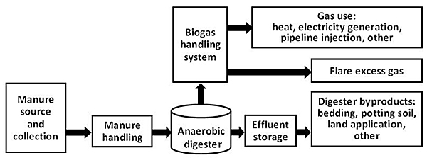
The stages of the anaerobic digestion process.
Anaerobic digesters are made out of concrete, steel, brick, or plastic. All anaerobic digestion system designs incorporate the following same basic components:
Batch digesters and continuous digesters are the two basic types of anaerobic digesters. Batch-type digesters are the simplest to build. Their operation consists of loading the digester with organic materials and allowing it to digest. The retention time depends on temperature and other factors. Once the digestion is complete, the effluent is removed and the process is repeated.
In a continuous digester, organic material is constantly or regularly fed into the digester. The material moves through the digester either mechanically or by the force of the new feed pushing out digested material. Unlike batch-type digesters, continuous digesters produce biogas without the interruption of loading material and unloading effluent. There are three types of continuous digesters: vertical tank systems, horizontal tank or plug-flow systems, and multiple tank systems.
Proper design, operation, and maintenance of continuous digesters produce a steady and predictable supply of usable biogas, which is better suited for large-scale operations.
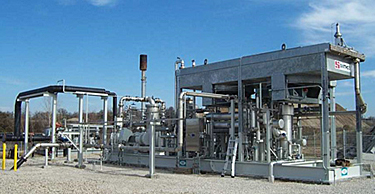
A landfill gas treatment station with blower and flare.
The same anaerobic digestion process that produces biogas from wastewater and animal manure occurs naturally underground in landfills. The waste is covered and compressed by the weight of the material that is deposited above. This material prevents oxygen exposure, thus allowing chemical reactions and microbes to act upon the waste, and encouraging an uncontrolled process of biomass decay. The rate of production is affected by waste composition and landfill geometry. Landfill gas is about 40% to 60% methane, with the remainder consisting mostly of carbon dioxide.
Landfill gas is extracted from landfills using a series of wells and a blower/flare system. According to the Landfill Methane Outreach Program, the system directs the collected gas to a central point where it can be processed and treated depending upon the ultimate use for the gas. A landfill gas collection system includes the following components:
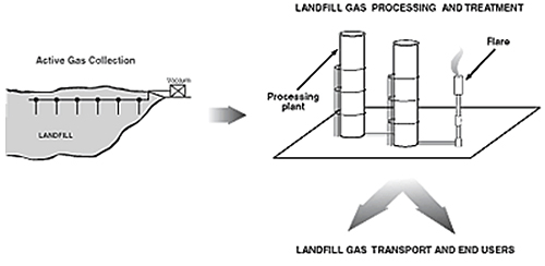
Diagram of a landfill gas system.
Biogas is most efficiently used in heating applications since the heat from combustion can be directly used. This requires the site to have a constant heating load throughout the year, which is common in building types such as hospitals and residential buildings. Biogas can also be used to operate a fuel cell or generator in order to make electricity. Where a facility does not have a consistent year-round heating load, such as a hospital or residence, electricity production may be the most valuable use of biogas.
Biogas can also be used for commercial electricity generation and direct combustion. Commercial electricity generation systems that use biogas consist of an internal combustion engine, a generator, a control system, and an optional heat recovery system. In addition, fuel cells can make use of biogas for electricity production. Direct combustion of biogas on-site in a boiler or forced air furnace can provide seasonal heat to facilities. More information on these applications is available from the Renewable Energy Institute.
See the Fuel Cells Resource Page for additional information on fuel cells.
Farms and ranches are common places where anaerobic digestion can make sense since there are typically large quantities of organic material available. Digesters effectively eliminate the environmental hazards of dairy farms and other animal feedlots. The environmental reasons typically motivate farmers more often than the digester's electrical or thermal energy generation potential does. Other potential common uses are zoos or any facility located near a continuous source of biomass such as a contained animal feeding operation.
EPA's AgSTAR program provides an array of information and tools designed to assist producers in the evaluation and implementation of these systems. In general, the system needs to be large, such as a contained animal feeding operation or a zoo. Federal agencies located near such facilities may want to investigate the possibility of a partnership to provide ongoing biogas to the facility.
When a Federal facility is located adjacent or near a landfill with either an existing gas recovery system or with the potential for landfill recovery, the agency may want to investigate the potential of a partnership with the landfill or work with a developer to create a biogas recovery process that would provide reliable renewable gas to the Federal facility.
The following economic factors should be considered for anaerobic digestion and landfill gas recovery systems.
Anaerobic digester system costs vary widely, especially since these types of systems can be put together using off-the-shelf materials. There are also a few companies that build system components. The design of these systems is critical, and they need to be carefully designed by experts to ensure that the process will actually digest the waste material under various operating conditions at the site. Before installing an anaerobic digester—also known as a biodigester—on a farm or ranch, it is recommended that the system's economic value and potential benefits be explored.
A biodigester usually requires manure from more than 150 large animals to generate electricity in the most cost-effective way. Anaerobic digestion and biogas production can also reduce overall operating costs where costs are high for sewage, agricultural, or animal waste disposal.
In the United States, the availability of inexpensive fossil fuels has limited the use of digesters solely for biogas production. However, the waste treatment and odor reduction benefits of controlled anaerobic digestion are receiving increasing interest, especially for large-scale livestock operations such as dairies, feedlots, and slaughterhouses. In many cases, the economics of a system are not based on lowest energy cost; but if a project can combine the on-farm benefits of a digester with a long-term contract for the biogas, the economics may make sense to either a farm or a developer.
As stated by EPA's Landfill Methane Outreach Program, current regulations under the Clean Air Act require many larger landfills to collect and combust landfill gas. There are several compliance options, including flaring the gas or installing a landfill gas use system. Only landfill gas energy recovery gives communities and landfill owners the opportunity to reduce the costs associated with regulatory compliance by turning pollution into a valuable community resource.
Again, the available energy may not be the driving force behind landfill gas recovery, but partnership with a Federal agency that is able to provide a long-term use for the biogas could improve the economics of this type of system.
For either an anaerobic digestion or landfill gas recovery system, the following resources need to be assessed.
Biogas recovery systems are technically feasible where manure is handled in a liquid, slurry, or semi-solid state, whereas digester systems are technically feasible only on certain farms. The number of animals and the type of manure management system are crucial. Anaerobic digesters are most adaptable to farms that collect large amounts of manure as a liquid or slurry. To determine if a biogas recovery system is right for a specific facility, the following factors must be considered:
To find out more information about whether a biogas recovery system is feasible for a specific facility, visit EPA's AgSTAR program.
The key points that need to be investigated to determine whether landfill gas capture is feasible are the age of the landfill, the size, and the types of gases generated. For landfill gas capture, it is best to have a newly capped landfill because the landfill gas production greatly declines after 20 to 30 years. The types of gases that are generated by the landfill can be determined by doing the following test: drilling a hole into the landfill, putting a vacuum on the landfill, and sampling the rate and types of gases being generated. A detailed landfill gas study should be done in order to determine the feasibility of landfill gas use. The EPA estimates that there are approximately 6,000 landfills in the United States. To see where all the existing tapped and candidate landfills are located, visit EPA's Landfill Methane Outreach Program. The website also includes a Landfill Gas Energy Benefits Calculator to estimate direct, avoided, and total greenhouse gas reductions for a particular project.
The following issues should be addressed before a landfill gas request for proposal is issued: public versus private ownership, law and policy, potential financial and non-financial benefits to the municipality, required and available resources, and a preliminary feasibility analysis. Procurement risks include too little or too much value to the municipality, capital and operating costs, access to debt and equity capital, access to Federal grant or Federal investment tax credit, sales prices of Renewable Energy Credits and electricity, and monetized value of carbon credits.
Typically, the source of biogas will not be on Federal property, and a separate ownership arrangement for the biogas system will be warranted. The agency should investigate various renewable energy project funding options for the project.
The Federal Energy Management Program (FEMP)'s Guide to Integrating Renewable Energy in Federal Construction has more information on renewable energy project funding.
For small-to-medium-sized digesters with electrical generators, operation and maintenance (O&M) costs include daily operator labor to perform routine maintenance and pump the manure. Other factors include expenses for engine oil changes and minor repairs, and maintenance such as engine overhauls and sludge removal. Annual O&M is estimated at 3% of the digester system turnkey cost.
O&M costs for a landfill gas collection system are approximately $25 per acre per month. This accounts for miscellaneous parts, replacements, monitoring, and labor for O&M of the gas collection system.
The following are important special considerations for biogas systems.
A biogas system that will be used for power production will need to be connected to the local utility grid and must meet interconnection requirements of the local utility. Many states or localities have guidelines that require interconnection of many customer-owned power projects. Some guidelines limit the size of a project that can be interconnected, or place a grid-wide limit on the amount of capacity a utility must interconnect. The local utility for the site is the best resource for interconnection rules.
A Federal agency should confirm early in the discussion with the utility if it can sign the utility interconnection agreement as there have been some cases where utility indemnification clauses prevented an agency from legally signing the agreement.
The Database of State Incentives for Renewables & Efficiency (DSIRE) is a comprehensive source of information on state, local, utility, and Federal incentives and policies that promote renewable energy and energy efficiency.
If the project is located on Federal land or uses Federal funding (besides a tax credit), it must comply with the National Environmental Policy Act (NEPA). Although both anaerobic digestion and landfill gas recovery systems have a net positive effect of removing harmful emissions from the air, they can still face issues with NEPA review. However, if the projects are not on Federal lands and are not owned by the agency, the NEPA process may not be required for certain systems. Consulting with an agency environmental expert on procedures for implementing NEPA is recommended.
The Renewable Energy Institute has additional information and resources on biogas technologies.
The EPA's AgSTAR program is a voluntary outreach and educational program that promotes the recovery and use of methane from animal manure.
The EPA's Landfill Methane Outreach Program (LMOP) is a voluntary assistance program that helps to reduce methane emissions from landfills by encouraging the recovery and beneficial use of landfill gas as an energy resource.
THIS PAGE SUPPORTED BY THE
Biomass is used for facility heating, electric power generation, and combined heat and power. The term biomass encompasses a large variety of materials, including wood from various sources, agricultural residues, and animal and human waste.
Biomass can be converted into electric power through several methods. The most common is direct combustion of biomass material, such as agricultural waste or woody materials. Other options include gasification, pyrolysis, and anaerobic digestion. Gasification produces a synthesis gas with usable energy content by heating the biomass with less oxygen than needed for complete combustion. Pyrolysis yields bio-oil by rapidly heating the biomass in the absence of oxygen. Anaerobic digestion produces a renewable natural gas when organic matter is decomposed by bacteria in the absence of oxygen.
Different methods work bet with different types of biomass. Typically, woody biomass such as wood chips, pellets, and sawdust are combusted or gasified to generate electricity. Corn stover and wheat straw residues are baled for combustion or converted into a gas using an anaerobic digester. Very wet wastes, like animal and human wastes, are converted into a medium-energy content gas in an anaerobic digester. In addition, most other types of biomass can be converted into bio-oil through pyrolysis, which can then be used in boilers and furnaces.

In Woodland, California, a generation station uses wood from the agricultural industry. Source: NREL
This overview focuses on woody biomass used for generating electricity at a commercial-scale facility rather than a utility-scale project. Biomass heat and biogas, including anaerobic digestion and landfill gas, are covered in other technology resource pages in this guide:
Compared to many other renewable energy options, biomass has the advantage of dispatchability, meaning it is controllable and available when needed, similar to fossil fuel electric generation systems. The disadvantage of biomass for electricity generation, however, is that the fuel needs to be procured, delivered, stored, and paid for. Also, biomass combustion produces emissions, which must be carefully monitored and controlled to comply with regulations.
This overview provides specific details for those considering biomass electric generation systems as part of a major construction project. Further general information is available from the U.S. Department of Energy (DOE) Office of Energy Efficiency and Renewable Energy (EERE) Biomass Technology Basics. Details on biomass use for combined heat and power is available from the U.S. Environmental Protection Agency's (EPA) Combined Heat and Power Partnership.
Most biopower plants use direct-fired combustion systems. They burn biomass directly to produce high-pressure steam that drives a turbine generator to make electricity. In some biomass industries, the extracted or spent steam from the power plant is also used for manufacturing processes or to heat buildings. These combined heat and power (CHP) systems greatly increase overall energy efficiency to approximately 80%, from the standard biomass electricity-only systems with efficiencies of approximately 20%. Seasonal heating requirements will impact the CHP system efficiency.
A simple biomass electric generation system is made up of several key components. For a steam cycle, this includes some combination of the following items:
Direct combustion systems feed a biomass feedstock into a combustor or furnace, where the biomass is burned with excess air to heat water in a boiler to create steam. Instead of direct combustion, some developing technologies gasify the biomass to produce a combustible gas, and others produce pyrolysis oils that can be used to replace liquid fuels. Boiler fuel can include wood chips, pellets, sawdust, or bio-oil. Steam from the boiler is then expanded through a steam turbine, which spins to run a generator and produce electricity.
In general, all biomass systems require fuel storage space and some type of fuel handling equipment and controls. A system using wood chips, sawdust, or pellets typically use a bunker or silo for short-term storage and an outside fuel yard for larger storage. An automated control system conveys the fuel from the outside storage area using some combination of cranes, stackers, reclaimers, front-end loaders, belts, augers, and pneumatic transport. Manual equipment, like front loaders, can be used to transfer biomass from the piles to the bunkers, but this method will incur significant cost in labor and equipment operations and maintenance (O&M). A less labor-intensive option is to use automated stackers to build the piles and reclaimers to move chips from the piles to the chip bunker or silo.
Wood chip-fired electric power systems typically use one dry ton per megawatt-hour of electricity production. This approximation is typical of wet wood systems and is useful for a first approximation of fuel use and storage requirements but the actual value will vary with system efficiency. For comparison, this is equivalent to 20% HHV efficiency with 17 MMBtu/ton wood.
Most wood chips produced from green lumber will have a moisture content of 40% to 55%, wet basis, which means that a ton of green fuel will contain 800 to 1,100 pounds of water. This water will reduce the recoverable energy content of the material, and reduce the efficiency of the boiler, as the water must be evaporated in the first stages of combustion.
The biggest problems with biomass-fired plants are in handling and pre-processing the fuel. This is the case with both small grate-fired plants and large suspension-fired plants. Drying the biomass before combusting or gasifying it improves the overall process efficiency, but may not be economically viable in many cases.
Exhaust systems are used to vent combustion by-products to the environment. Emission controls might include a cyclone or multi-cyclone, a baghouse, or an electrostatic precipitator. The primary function of all of the equipment listed is particulate matter control, and is listed in order of increasing capital cost and effectiveness. Cyclones and multi-cyclones can be used as pre-collectors to remove larger particles upstream of a baghouse (fabric filter) or electrostatic precipitator.
In addition, emission controls for unburned hydrocarbons, oxides of nitrogen, and sulfur might be required, depending on fuel properties and local, state, and Federal regulations.
In a direct combustion system, biomass is burned in a combustor or furnace to generate hot gas, which is fed into a boiler to generate steam, which is expanded through a steam turbine or steam engine to produce mechanical or electrical energy.
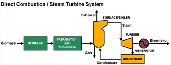
In a direct combustion system, processed biomass is the boiler fuel that produces steam to operate a steam turbine and generator to make electricity.
There are numerous companies, primarily in Europe, that sell small-scale engines and combined heat and power systems that can run on biogas, natural gas, or propane. Some of these systems are available in the United States, with outputs from about 2 kilowatts (kW), and approximately 20,000 British thermal units (Btu) per hour of heat, to several megawatts (MW). In addition, small-scale (100 to 1,500 kW) steam engine/gen-sets and steam turbines (100 to 5,000 kW) that are fueled by solid biomass are currently available in Europe.
In the United States, direct combustion is the most common method of producing heat from biomass. Small-scale biomass electric plants have installed costs of $3,000 to $4,000 per kW, and a levelized cost of energy of $0.8 to $0.15 per kilowatt hour (kWh).
The two principal types of chip-fired direct combustion systems are stationary- and traveling-grate combustors, otherwise known as fixed-bed stokers and atmospheric fluidized-bed combustors.
There are various configurations of fixed-bed systems, but the common characteristic is that fuel is delivered in some manner onto a grate where it reacts with oxygen in the air. This is an exothermic reaction that produces very hot gases and generates steam in the heat exchanger section of the boiler.
In either a circulating fluidized-bed or bubbling fluidized-bed system, the biomass is burned in a hot bed of suspended, incombustible particles, such as sand. Compared to grate combustors, fluidized-bed systems generally produce more complete carbon conversion, resulting in reduced emissions and improved system efficiency. In addition, fluidized-bed boilers can use a wider range of feedstocks. Furthermore, fluidized-bed systems have a higher parasitic electric load than fixed-bed systems due to increased fan power requirements.
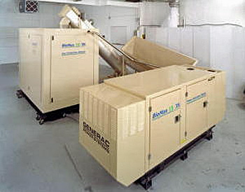
Small, modular biopower system by Community Power Corporation
Although less common, biomass gasification systems are similar to combustion systems, except that the quantity of air is limited, and thus produce a clean fuel gas with a usable heating value in contrast to combustion, in which the off gas does not have a usable heating value. Clean fuel gas provides the ability to power many different kinds of gas-based prime movers, such as internal combustion engines, Stirling engines, thermo electric generators, solid oxide fuel cells, and micro-turbines.
The efficiency of a direct combustion or biomass gasification system is influenced by a number of factors, including biomass moisture content, combustion air distribution and amounts (excess air), operating temperature and pressure, and flue gas (exhaust) temperature.
The type of system best suited to a particular application depends on many factors, including availability and cost of each type of biomass (e.g. chip, pellet, or logs), competing fuel cost (e.g. fuel oil and natural gas), peak and annual electrical loads and costs, building size and type, space availability, operation and maintenance staff availability, and local emissions regulations.
Projects that can make use of both electricity production and thermal energy from biomass energy systems are often the most cost effective. If a location has predictable access to year-round, affordable biomass resources, then some combination of biomass heat and electricity production may be a good option. Transportation of fuel accounts for a significant amount of its cost, so resources should ideally be available from local sources. In addition, a facility will typically need to store biomass feedstocks on-site, so site access and storage are factors to consider.
As with any on-site electricity technology, the electricity generating system will need to be interconnected to the utility grid. The rules for interconnection may be different if the system is a combined heat and power system instead of only for electricity production. The ability to take advantage of net metering may also be crucial to system economics.
The Federal Energy Management Program (FEMP)'s Guide to Integrating Renewable Energy into Federal Construction has more information on interconnection requirements and net metering.
The major capital cost items for a biomass power system include the fuel storage and fuel handling equipment, the combustor, boiler, prime mover (e.g. turbine or engine), generator, controls, stack, and emissions control equipment.
System cost intensity tends to decrease as the system size increases. For a power-only (not combined heat and power) steam system in the 5 to 25 MW range, costs generally range between $3,000 and $5,000 per kilowatt of electricity. Levelized cost of energy for this system would be $0.08 to $0.15 per kWh, but this could increase significantly with fuel costs. Large systems require significant amounts of material, which leads to increasing haul distances and material costs. Small systems have higher O&M costs per unit of energy generated and lower efficiencies than large systems. Therefore, determining the optimal system size for a particular application is an iterative process.
A variety of incentives exist for biomass power, but vary with Federal and state legislation policies. The Database of State Incentives for Renewables & Efficiency® lists incentives for biomass. The timing of incentive programs often allows less construction time than needed for biomass projects. Also, Federal agencies often cannot take direct advantage of financial incentives for renewable energy unless they use a different ownership structure.
FEMP's Guide to Integrating Renewable Energy into Federal Construction has more information on renewable energy project funding.
Of interest, the State of Massachusetts recently removed biomass-fired electricity from its Renewable Portfolio Standard, because state officials did not believe that biomass provided a clear reduction in greenhouse gases. As such, biomass projects no longer qualify for renewable energy certificates that count toward Massachusetts renewable energy goals or funding.
The most important factors in planning for a biomass energy system are resource assessment, planning, and procurement. As part of the screening and feasibility analysis processes, it is critical to identify potential sources of biomass and to estimate the fuel quantities needed.
If possible, determine, in detail, the capability of potential suppliers to produce and deliver a fuel that meets the requirements of the biomass equipment. This can be a bit of an intensive process as it involves determining the load to be served, identifying possible equipment manufacturers or vendors, working with those vendors to determine a fuel specification, and contacting suppliers to see if they can meet the specification—and at what price. It is also necessary to estimate the monthly and annual fuel requirement, as well as peak fuel use, to help with fuel handling and fuel storage equipment sizing.
Since there is no established wood chip distribution system in most of the United States, it is sometimes difficult to find suppliers. One suggestion is to contact the regional U.S. Forest Service and state forest service offices. Other resources to contact include landscape companies, lumber mills, and other wood processors, landfills, arborists, and wood furniture manufacturers.
County-level biomass resource estimates are also available online through an interactive mapping and analysis tool. The Biomass Assessment Tool was developed by the National Renewable Energy Laboratory (NREL) using funding from EPA. Previously, resource assessment efforts were usually static and did not allow user analysis or manipulation of the data. This new tool enables users to select a location on the map, quantify the biomass resources available within a user-defined radius, and estimate the total thermal energy or power that could be generated by recovering a portion of that biomass. The tool acts as a preliminary source of biomass feedstock information; however, it cannot take the place of an on-the-ground feedstock assessment.
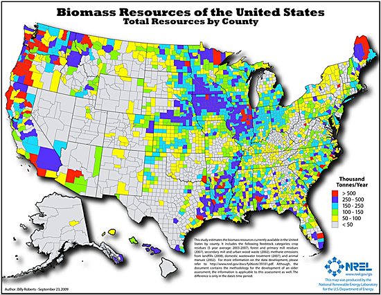
Available biomass resources in the United States. Source: NREL
A process must be developed to receive biomass deliveries and to assess the fuel properties. As of July 2011, there are no national wood chip specifications, but regional specifications are being developed. Having a specification helps to communicate and enforce chip requirements. The specification should include physical dimensions, fuel moisture content range, energy content, ash and mineral content, and other factors that affect fuel handling or combustion. To ensure fair value, fuel procurement contracts should scale purchase price inversely with moisture content, as higher moisture content significantly decreases combustion efficiency and increases the weight of material to be transported.
The following recommendations are critical to the success of any biomass energy project.
O&M costs of biomass energy systems are predominately the costs of fuel and labor. In other respects, these systems are similar to other boiler-based electricity production systems. Operation is continual, so costs for operation and for the purchase and storage of fuel need to be assessed with the overall project costs.
The following are important special considerations for biomass electric systems.
The primary NEPA and permitting issue with a biomass energy system is the combustion emissions. Therefore, local requirements should be reviewed. Air emissions from a biomass system depend on the system design and fuel characteristics. If necessary, emissions controls systems can be used to reduce particulate matter and oxides of nitrogen emissions. Sulfur emissions are completely dependent on the sulfur content of the biomass, which is usually very low.
The storage of wood chips requires consideration, preparation, and attentiveness. When the chips are stored in a building, there is potential for dust from the chips to build up on horizontal surfaces and to get inside equipment. A concern, though rare in occurrence, is the wood chips' ability to self-ignite, or spontaneously combust, when stored for long periods of time. For more information see OSHA's safety and health information bulletin, Combustible Dust in Industry: Preventing and Mitigating the Effects of Fire and Explosions.
This is due to a chain of events, which starts with the biological breakdown of the organic matter and can lead to smoldering of the pile. The critical moisture range that supports spontaneous combustion is roughly 20% to 45%. The probability of spontaneous combustion also increases as pile size increases, due to the increasing depth.
To help with this issue, the Office of the Fire Marshal fire code in Ontario, Canada provides the following guidelines:
The storage site shall be well-drained and level, solid ground or paved with asphalt, concrete, or other hard surface material. The ground surface between piles shall be kept free of combustible materials. Weeds, grass, and similar vegetation shall be removed from the yard. Portable open-flame weed burners shall not be used in chip storage yards. Piles shall not exceed 18 m (59 ft) in height, 90 m (295 ft) in width, and 150 m (492 ft) in length unless temporary water pipes with hose connections are laid on the top surface of the pile.
Space shall be maintained between chip piles and exposing structures, yard equipment, or stock equal to (a) twice the pile height for combustible stock or buildings, or (b) the pile height for non-combustible buildings and equipment.
Smoking shall be prohibited in chip pile areas.
Wood chip fires can be caused by other factors, such as lightning strikes, heat from equipment, sparks from welding activities, wildfires, and arson. These fires are sometimes called surface fires because they start, and spread, along the exterior of the pile.
For storage, it is critical to keep the wood chips clean. When chips are stored on dirt or gravel, some of this material will often get scooped up along with the chips and end up in the combustor.
On February 21, 2011, EPA established Clean Air Act emissions standards for large and small boilers and incinerators that burn solid waste and sewage sludge. These standards cover more than 200,000 boilers and incinerators that emit hazardous air pollutants (HAP), also known as air toxics. The new EPA standards should be followed as part of project planning for any combustion boiler.
EPA also enacted Clean Air Act Permitting for Greenhouse Gas Emissions on January 2, 2011. Also referred to as the "tailoring rule," this process requires permitting for greenhouse gas production, but exempts smaller facilities. Final rules are expected to be developed over a three-year study period, but Federal facilities using biomass electricity production as part of a new construction project may want to ensure the size of the biomass facility does not trigger these requirements.
In 2009, the State of Massachusetts issued a document titled Biomass Boiler & Furnace Emissions and Safety Regulations in the Northeast States . Although this document provides a review of existing regulations in that region, it can be a useful reference for other parts of the country.
The following additional resources can provide further detail on biomass electricity generation.
THIS PAGE SUPPORTED BY THE
Biomass is used for facility heating and, to a lesser extent, for electric power generation and combined heat and power. The term biomass encompasses a large variety of materials, including wood from various sources, agricultural residues, and animal and human waste. The focus of this section is limited to woody biomass for heat only. Biomass electricity, biogas from landfill gas, and anaerobic digestion, are covered in other technology resource pages in this guide:
Woody biomass is commonly used for facility heating in three forms: whole logs or firewood, wood chips, and wood pellets. Systems are available from 6,000 British thermal units (Btu)/hr to over 100 million Btu/hr. Small systems, particularly small- and mid-size pellet and log systems, are available off-the-shelf from numerous manufacturers. Larger pellet systems and wood chip-fired systems are commercially available from several companies. The larger systems typically require both facility modification and system customization, mainly for integration of the fuel storage and handling and conveying systems.
Biomass systems require more operator interaction than other renewable energy systems such as solar and wind. This includes ordering and delivering fuel, removing ash, and maintaining moving parts. Overall, however, biomass heating systems typically only require a few minutes of attention each day, plus a few hours per year for annual maintenance.
Compared to most other renewable energy options currently available, biomass has the advantage of dispatchability, meaning it is controllable and available when needed, similar to fossil fuel heating and electric generation systems. The disadvantage of biomass for facility heating is that the fuel needs to be purchased, procured, delivered, and stored. Biomass combustion also produces emissions, which must be monitored and controlled to comply with regulations.
This overview is intended to provide specific details for Federal agencies considering biomass heating technologies as part of a new construction project or major renovation. Further general information on biomass heating is available from the Biomass Energy Resource Center.
A biomass heating system is made up of several key components, which include some combination of the following items:
For smaller systems, like pellet and wood stoves, these components are largely integrated into one packaged unit, and only require ducting of the exhaust through a wall or chimney. Mid-sized pellet and wood chip systems often use one or more silos for fuel storage. The silo will need to be located for convenient delivery access, usually outside, which will require some form of conveyor system to move the fuel to the combustion unit. Larger wood chip systems usually require more integration with the building in which it is housed, particularly if a chip bunker is part of the building structure.
All biomass systems require fuel storage space and usually some sort of fuel handling equipment and controls. A system using wood chips or pellets usually stores the fuel in a bunker or silo. An automated control system conveys the fuel from the storage area using a combination of belts, augers, or pneumatic transport. The fuel storage volume can be sized to supply a quantity of fuel that will last from one day up to several weeks.
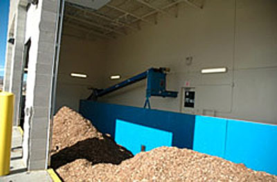
Wood chip storage at the Boulder County Parks and Open Space campus district heating system. This system has three large bay doors through which chips are delivered into an underground pit where a series of augers and belts deliver the chips to the combustor.
It is generally recommended that this storage be sized to provide enough fuel for a minimum of three days of operation to get through a long, cold weekend without additional fuel deliveries. In addition, a larger supply of fuel is often located nearby to decrease the chances of running out of fuel during severe weather.
A metering bin or surge bin is often the last section of the fuel handling system, and controls the rate at which fuel is delivered to the combustor. The combustor is also called the firebox or reactor. Pellet and log systems can be used to directly heat air as the heat transfer medium, or they can heat water in a boiler or hot water system, known as a hydroponic heating system. Chip combustion systems almost always use water as a heat transfer medium.
The combustor and boiler can be configured end-to-end or the boiler can be mounted on top of the combustor. The first configuration requires more floor space and the second requires more vertical clearance. Some manufacturers of larger biomass heating equipment make all of the system components, including the boiler/heat exchanger and the combustor. Others specialize in specific components, like the combustor and fuel handling systems, and in integrating components into complete systems.
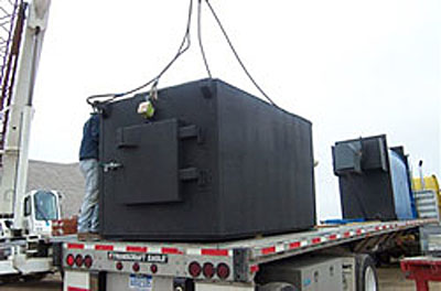
Combustor and boiler delivery, Boulder County, Colorado
One potential area for confusion when specifying biomass heating systems is the variety of unit systems used in specifying system capacity. Heating systems are described in terms of Btu per hour (frequently incorrectly stated as simply Btu), or million Btu per hour (abbreviated variously as MMBtu/hr, MBtu/hr, or MMBtuh), watts (W), kilowatts (kW), or megawatts (MW), boiler horsepower (1 horsepower is roughly equal to 9,810 W or 33,479 Btu/hr), pounds of steam per hour, equivalent direct radiation (EDR), and others. Some vendors specify system size in terms of fuel input, though most system size designations are in terms of boiler output capacity. Similar confusion is possible in stating heating system efficiency, particularly with a high-moisture content fuel like wood chips. This makes calculating the fuel input requirements for a given space's heating load particularly challenging.
A fire suppression system is sometimes used to prevent fire from spreading from the combustor back up through the conveyor system where the wood chips are held in the metering bin. For example, this system might include a temperature sensor mounted on the feed system just upstream of the combustor as well as a water-delivery and control system to quench any fire before it spreads through the feed system.
In a hydronic system, which uses steam or hot water, pumps are used to circulate water from the hot water tank to spaces or buildings being heated by the system, through flow valves controlled by a thermostat or other temperature controller.
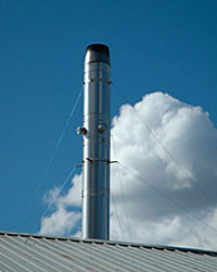
Exhaust stack on a biomass system at a California greenhouse
Biomass heating systems generally use a combination of induced-draft and forced-draft fans to control combustion air into the firebox and to force air through any emissions controls systems.
Exhaust systems are used to vent combustion by-products, primary carbon-dioxide, and water to the atmosphere. Emissions controls might include a cyclone or multi-cyclone, a baghouse, or an electrostatic precipitator (listed in order of increasing capital cost and effectiveness) to capture particulate matter. Cyclones and multi-cyclones can be used as pre-collectors to remove larger particles upstream of a baghouse (fabric filters) or electrostatic precipitator.
System controls generally coordinate the functioning of the conveyor systems, combustion fans, igniters, soot blowers, automatic ash handling equipment, and backup boilers, and often include diagnostic systems and alarm systems to notify operators of system problems. Some systems can include phone dialers that are programmed to send text or e-mail messages and can be Web-enabled to allow remote viewing of system parameters.
Woody biomass typically contains 1% to 5% ash content, which is non-combustible material. To ensure that the system continues functioning properly, this ash must be removed periodically from the system. In some systems, ash is removed manually, using a special rake or shovel. In other systems, augers automatically remove the ash from the firebox and deliver it to a barrel or other container for disposal.
Inclusion of the automated system will increase capital cost, but will decrease operation and maintenance costs.
Biomass-fired heating systems often include a secondary fossil fuel-fired heating unit. This offers several advantages, including:
Many facilities include a backup boiler even with a fossil-fuel system. In that case, the backup boiler cost would not count against the biomass financial analysis.
Smaller biomass-fired systems are often located in the space to be heated, which allows for space heating through radiation and natural and forced convection. Larger systems are usually tied into hydronic distribution systems, which provide space heating through radiant floor or baseboard systems. In the photo of the biomass-fired boiler, some of the distribution piping is visible. This particular system uses the insulated, underground piping to carry the hot water to several buildings at the campus.
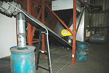
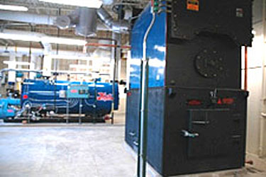
Automated ash-removal system on a wood-fired boiler. The system uses an auger to remove the ash from the boiler (lower right) and delivers it to the blue barrel on the left.
A biomass-fired boiler (right foreground) and a Hurst natural gas-fired backup boiler (left background)
Direct combustion is the most common method of producing heat from biomass. In a direct combustion system, the biomass is burned to generate hot gas, which is either used directly to provide heat or fed into a boiler to generate hot water or steam. In a boiler system, the steam can be used to provide heat for process or space heating. The hot water or steam from the boiler can be used to transfer heat to a facility through typical space heating methods.
If the system is used as a combined heat and power system, the boiler can produce steam to run a turbine and power a generator, and remaining steam and hot water can then be used for heating.
The two principal types of chip-fired direct combustion systems are stationary- and traveling-grate combustors, otherwise known as fixed-bed and atmospheric fluidized-bed systems. Biomass heating plants have installed costs that typically average between $500 to $1500 per kW-thermal of installed heating rate capacity. As these involve mature technologies, costs are not expected to drop significantly in the short term.
There are various configurations of fixed-bed systems, but the common characteristic is that fuel is delivered onto a grate where it reacts with oxygen in the air blown through the firebox. This is an exothermic reaction that produces very hot gases and generates steam in the heat exchanger section of the boiler.
In either a circulating fluidized-bed or bubbling fluidized-bed system, the biomass is burned in a hot bed of suspended, incombustible particles, such as sand. Fluidized-bed systems generally achieve more complete carbon conversion, resulting in reduced emissions and improved system efficiency. In addition, compared to fixed-bed systems, fluidized-bed boilers can use a wider range of feedstocks. Fluidized-bed systems also have a higher electric load than fixed-bed systems due to increased fan power requirements.
Biomass gasification systems are similar to combustion systems, except that the quantity of air is limited. This process converts the biomass to a hot gas, which can be combusted in a boiler.
The efficiency of a direct combustion system is influenced by a number of factors, including biomass moisture content, combustion air distribution and amounts (excess air), operating temperature and pressure, and flue gas (exhaust) temperature. A typical biomass system operating on fuel with a moisture content of 40% has a net efficiency of about 60% to 65%. Although the wood can be dried before combustion to increase efficiency, this is not typically done in practice because of the need for additional equipment and higher initial cost.
The type of system best suited to a particular application depends on many factors, including: availability and cost of each type of biomass (e.g. chip, pellet or logs), competing fuel cost (e.g. fuel oil and natural gas), thermal peak and annual load, building size and type, space availability, operation and maintenance (O&M) staff availability, and local emissions regulations.
For buildings or campuses with more than 100,000 ft² to heat in a moderately cold climate, a system fuelled with wood chips will probably be the most economical, assuming that there is a stable local chip supply. The economics are even better for buildings with a year-round hot water or steam load or when competing against high-priced fossil fuels.
For buildings less than 10,000 ft² in a moderately cold climate, a wood pellet system might be the best option. These systems can be manually loaded with 40-lb bags of pellets. For larger systems, it is usually best to have pellets delivered in bulk (not bagged), where bulk delivery is available. These systems usually use a pellet silo or bunker to store large quantities of pellets. As a result, the pellets can be automatically conveyed from the silo to the pellet stove, pellet furnace, or pellet boiler.
Another option for smaller buildings is a cordwood system. The best of these systems have a burner surrounded by a large water jacket. The cordwood is loaded in batches and burned at full fire to heat the water. The hot water is a thermal energy storage medium that is circulated through the building's heaters as controlled by thermostats.
Some cordwood systems reduce burn rate by throttling combustion air, but this results in low efficiency and very high emissions of particulate matter and unburned hydrocarbons. As a result, these systems are not recommended, and are illegal in many jurisdictions.
Facilities with a high capacity factor (i.e., high average annual thermal load) are often good candidates for biomass heating. The capital costs for biomass heating systems are significantly higher than the costs for fossil-fuel plants, but savings on fuel use reduce the levelized cost of energy over time. The types of facilities for which biomass is usually a good investment include hospitals, prisons, school campuses, or other institutions where hot water use results in high load for all seasons. Additionally, biomass heating will not be cost effective if the competing heating fuel is significantly more expensive than the biomass feedstock.
A variety of incentives exist for biomass power, but vary with Federal and state legislation and policies. The Database of State Incentives for Renewables & Efficiency (DSIRE) lists incentives for biomass. The timing of incentive programs often allows less construction time than needed for biomass projects.
Federal agencies often cannot take direct advantage of financial incentives for renewable energy unless they use a different ownership structure. The Federal Energy Management Program (FEMP)'s Guide to Integrating Renewable Energy in Federal Construction has more information on renewable energy project funding.
Levelized cost of energy for heating with biomass is typically $10 to $20 dollars per million Btu, but this is highly dependent on the feedstock cost and quality and on O&M costs. Federal agencies should consult local biomass experts for a better understanding of the available biomass resources and the available production and costs of energy from those resources.
The most important factors in planning for a biomass energy system are resource assessment, planning, and procurement. As part of the screening and subsequent feasibility analysis, it is critical to identify potential sources of biomass, and to estimate the fuel quantities needed.
Because of the complexity of determining available biomass resources and the usefulness of various types of biomass, Federal agencies should consult regional biomass experts to determine the available resources to a particular facility. They will need to determine, in detail, the capability of potential suppliers to produce and deliver a fuel that meets the requirements of the biomass heating system. For woody biomass, it is important to ask about:
Since there is no established wood chip distribution system in most of the United States, it is sometimes difficult to find suppliers. One resource to contact is the regional U.S. Forest Service and state forest service offices. Other resources include landscape companies, lumber mills and other wood processors, landfills, arborists, and wood furniture manufacturers.
A process must be developed to receive biomass deliveries and to assess the fuel properties. As of July 2011, there are no national wood chip specifications, but regional specifications are being developed. Having a specification helps to communicate and enforce chip requirements. The specification should include: physical dimensions, fuel moisture content range, energy content, ash and mineral content, and other factors that affect fuel handling or combustion. It is recommended that fuel procurement contracts scale purchase price inversely with moisture content, as higher moisture content significantly decreases combustion efficiency and increases the weight of material to be transported.
The following recommendations are critical to the success of any biomass energy project.
This section presents the steps involved in analyzing and installing a wood-fired heating system. Following is a brief outline of that process. The steps are not necessarily sequential; during the first steps, some iteration is expected as questions arise and knowledge is gained.
The purpose of the screening step is to see if a wood-fired heating system makes sense for a particular facility. A quick economic analysis should be performed to estimate capital costs relative to potential annual savings. A discussion should be held with O&M staff, management, and other affected parties to determine the organization's ability to support biomass heating.
If the concept of biomass heating passes the initial quick filter, it is time to learn more about biomass heating systems. Review manufacturers' websites and literature, talk to others with knowledge of biomass heating, and consider scheduling an appointment to visit similar regional installations.
Research the cost and availability of biomass fuel in the area and keep in mind that long haul distances increase chip cost. Search for potential suppliers that are able to deliver wood chips to the designated facility. Eventually there will be a need to select one or more suppliers whose delivery vehicles are compatible with the chosen system.
At this stage, it would be beneficial to have a feasibility study performed by a firm with experience in biomass heating systems. The study will cover most of the topics in this document and provide a detailed economic analysis of heating and comparison of wood versus conventional fuel. The feasibility study can also determine how well a biomass heating system will help meet the facility's energy requirements and goals.
The size of the wood-fired system should be based on the peak load. Compared to an undersized system, an oversized system will not perform as well, will be inefficient, and will have higher emissions. A supplemental boiler, using a conventional fuel, will almost always be needed and will be sized to meet the peak load. The wood-fired boiler can be sized at 50% to 80% of the peak load, and still meet 90% to 95% of the annual load. The smaller system will have lower capital costs and will operate more efficiently than a large system. An economic analysis can be used to determine the optimal size of the wood-fired system.
Estimate heating energy use and expenses for a wood-fired system and for a system using alternate fuel such as natural gas, propane, and heating oil. The annual cost of wood versus alternate fuel will be a factor in the economic analysis, and will also be used to estimate air emissions, ash production, fuel storage requirements, and wood delivery schedules.
After sufficient information has been gathered, it is time to decide if proceeding with a biomass heating system fulfills the facility's specific needs, goals, and economic requirements.
If it is in the best interest to pursue a biomass heating system, be sure to fully involve decision-makers and the general public during the planning stages and as progress is made, particularly if the system is to be installed in a public building.
O&M costs of biomass heating systems are predominately the costs of fuel and labor. A well-operated and maintained wood chip-fired heating system should require 2 to 5 hours of O&M per week during the heating season. This includes fuel ordering and a daily walk-through.
The following is a conservative initial maintenance plan. As the operators become familiar with the equipment, this plan can be modified as needed. Many installations can go significantly longer between maintenance routines than the amount of time indicated here.

Ash resulting from wood combustion
Grate maintenance consists of cooling the box down slightly, and scraping the grate with a rake or hoe. Ash removal can be automated or manual. Manual ash removal takes about 10 minutes and should initially be done about twice a week. If there has been light use, systems can go as long as two weeks between cleanings.
Boiler tube cleaning is also dependent on use. Most systems in schools clean these tubes twice a year—once during the summer and once during a mid-season shut down (during the holiday period). By monitoring the stack gas temperature, the frequency of required boiler tube cleaning can be determined.
Equipment maintenance consists of lubricating gear drives and occasionally replacing seals, bearings, and gaskets. Depending on the size of the facility, a $1,000 to $2,000 per year "sinking fund" will normally cover any equipment maintenance required.
Additional operating costs include the cost to move the wood around on-site, and to load the hopper from a larger storage area. This handling has been estimated to cost about $3,000 per year for a medium-sized chip system.
The following are important special considerations for biomass heating systems.
The primary NEPA and permitting issue with a biomass heating system is the combustion emissions. Therefore, local requirements should be consulted. Air emissions from a biomass system depend on the system design and fuel characteristics. The following table shows typical emissions for a biomass heating system (based on CHIPTEC gasifier data) operating on 40% moisture content pine. If necessary, emissions controls systems can be used to reduce particulate matter (PM) and oxides of nitrogen (NOx) emissions. Sulfur emissions are completely dependent on the sulfur content of the biomass, which is usually very low.
Air emissions for a typical biomass heating system (lb/green ton)
| Constituent | PM10 | NOx | VOC | CO |
| Typical biomass system emissions | 2.1 | 2.8 | 0.6 | 1.7 |
The storage of wood chips also raises a few issues. When the chips are stored in a building, there is a potential for dust from the chips to build up on horizontal surfaces and to get inside the equipment. For this reason, many facilities either store the chips in silos or enclosed containers, or build a dust wall to limit this dust to a small area.
Another concern, though rare in occurrence, is the ability of wood chips to self-ignite, or spontaneously combust, when stored for long periods of time. This is due to a chain of events, which starts with the biological breakdown of the organic matter and can lead to smoldering of the pile. The critical moisture range that supports spontaneous combustion is roughly 20% to 45%. The probability of spontaneous combustion also increases as pile size increases, due to the decreasing surface area-to-mass ratio.
Ontario, Canada, has experienced some wood chip fires. To help with this issue, the Office of the Fire Marshal fire code provides the following guidelines:
The storage site shall be well-drained and level, solid ground or paved with asphalt, concrete, or other hard surface material. The ground surface between piles shall be kept free of combustible materials. Weeds, grass, and similar vegetation shall be removed from the yard. Portable open-flame weed burners shall not be used in chip storage yards. Piles shall not exceed 18 m in height, 90 m in width, and 150 m in length unless temporary water pipes with hose connections are laid on the top surface of the pile.
Space shall be maintained between chip piles and exposing structures, yard equipment, or stock equal to (a) twice the pile height for combustible stock or buildings, or (b) the pile height for noncombustible buildings and equipment.
Smoking shall be prohibited in chip pile areas.
Wood chip fires can also be caused by other factors, such as lightning strikes, heat from equipment, sparks from welding activities, wildfires, and arson. These fires are sometimes called surface fires because they start, and spread, along the exterior of the pile.
For storage, it is recommended to keep the wood chips clean. When chips are stored on dirt or gravel, some of this material will often get scooped up along with the chips and end up in the combustor.
On February 21, 2011, EPA established Clean Air Act emissions standards for large and small boilers and incinerators that burn solid waste and sewage sludge. These standards cover more than 200,000 boilers and incinerators that emit harmful air pollution, including mercury, cadmium, and particle pollution.
The EPA also enacted Clean Air Act Permitting for Greenhouse Gas Emissions on January 2, 2011. This process requires permitting for greenhouse gas production, but exempts smaller facilities. Final rules are expected to be developed over a three-year study period, but Federal facilities using biomass electricity production as part of a new construction project may want to ensure the size of the biomass facility does not trigger these requirements.
In 2009, the State of Massachusetts issued the Biomass Boiler & Furnace Emissions and Safety Regulations in the Northeast States . Although this document provides a review of existing regulations in that region, it can be a useful reference for other parts of the country.
The Biomimicry Institute defines biomimicry as the science and art of emulating Nature's best biological ideas to solve human problems. For billions of years nature—animals, plants, and even microbes—has been solving many of the problems we are still dealing with today. Each has found what works, what is appropriate, and what lasts.
Biomimicry and biomimetics come from the Greek words bios, meaning life, and mimesis, also meaning to imitate. Scientist and author Janine Benyus popularized the term biomimicry in her 1997 book Biomimicry: Innovation Inspired by Nature. Benyus believes that most of the problems that have ever existed have already been solved by nature. Benyus suggests shifting one's perspective from learning about nature to learning from nature as a way to solve human problems. Sustainability issues are among those that can be addressed by applying the biomimicry process to a project. Utilizing an integrated design process can help open up opportunities to identify biological solutions to building problems and include the perspective of nature in the design process—as it is likely that nature already offers a solution.
Humans have always looked to nature for inspiration to solve problems. Leonardo da Vinci applied biomimicry to the study of birds in the hope of enabling human flight. He very closely observed the anatomy and flight of birds, and made numerous notes and sketches of his observations and countless sketches of proposed "flying machines". Although he was not successful with his own flying machine, his ideas lived on and were the source of inspiration for the Wright Brothers, who were also inspired by their observations of pigeons in flight. They finally did succeed in creating and flying the first airplane in 1903.

Leonardo's design for a flying machine, c. 1488, inspired by birds in flight. Pigeons also influenced the Wright Brothers' design for the first airplane.
Recent success stories exist in terms of how biomimicry can be applied to building design. While buildings serve to protect us from nature's extremes, this does not mean that they do not have anything to learn from the biological world. In fact, nature regularly builds structures with functionality that human-built structures could usefully emulate. Biomimetic research, science, and applications continue to grow and are already influencing the next generation of building products and systems as well as whole building designs.
For example, photovoltaic systems, which harvest solar energy, are a first step at mimicking the way a leaf harvests energy. Research is underway to create solar cells that more closely resemble nature. These cells are water-gel-based—essentially artificial leaves—that couple plant chlorophyll with carbon materials, ultimately resulting in a more flexible and cost-effective solar cell. (For more information see this article in Scientific American)


A photovoltaic system collects energy from the sun, which was inspired by the way leaves harvest sunlight as part of photosynthesis.
The bumpy surface of a lotus leaf (computer graphic close up view below-left) acts as a self-cleaning mechanism allowing dirt to be cleansed off the surface naturally by water, for instance, during a rain shower. Even the smallest of breezes on the plant causes a subtle shift in the angle of the plant allowing gravity to remove the dirt without the plant having to expend any energy. This same idea has been applied to the design of new building materials such as paints, tiles, textiles, and glass that reduce the need for detergents and labor and also reduces maintenance and material replacement costs.


Researchers have also developed non-toxic, formaldehyde-free wood glue that is now used in hardwood, plywood, and particleboard projects. The researchers discovered how to do this by understanding how blue mussels attach firmly under the water using flexible, thread-like tentacles.


The Thorny Devil, a desert lizard, gathers all the water it needs directly from rain, standing water, or from soil moisture, against gravity without using energy or a pumping device. Water is conveyed to the lizard's mouth by capillary action through a circulatory system on the surface of its skin. This same concept could be applied to passive collection and distribution systems of naturally distilled water which would reduce the energy consumed in collecting and transporting water by pump action (e.g., to the tops of buildings), and provide other inexpensive technological solutions such as managing heat through evaporative cooling systems, and protecting structures from fire through on-demand water barriers.


Damage to an organism naturally elicits a healing response. Bone is also known to detect damage to itself and can heal within range of its initial strength. This same concept has been applied to synthetic material design and contributed to the development of a self-healing polymer for use as building materials. Tiny capsules containing a healing agent are embedded in the polymer. When the material is damaged, the capsules rupture and release the healing agent, which repairs the cracks. The self-repairing capabilities of materials can contribute to reduced maintenance and material replacements costs as well as increased durability. Self-repairing materials can also be made lighter, resulting in reduced embodied energy and greenhouse gas production.


Inspired by biological systems that heal themselves when damaged, a self-healing polymer, created at the Beckman Institute, University of Illinois is being applied to the development of a structural polymeric building material, such as cladding, with the ability to self-heal cracks.
The Biomimicry Institute, a not-for-profit organization that promotes learning from and then emulating natural forms, processes, and ecosystems to create more sustainable and healthier human technologies and designs, suggests that the design team look at nature as "model, measure, and mentor." There are hundreds of technologies inspired by proven design systems existing in nature. One can become more familiar with these examples by broadening and deepening an inner awareness of nature.
AskNature, developed by the Biomimicry Institute, is a free, open source, online project designed to inspire innovation and technologies that create conditions conducive to life. To accomplish this, AskNature is organizing the world's biological literature by function along with providing access to biological blueprints and strategies, bio-inspired products and design sketches, and access to experts to talk with and collaborate with to solve problems. To utilize the tool and apply this broader method of thinking into a building project, begin by asking:
The Biomimicry Guild, in collaboration with other organizations, developed a practical design tool called the Biomimicry Design Spiral that uses nature as a model. This tool outlines guidance using the following steps to apply the tool effectively and systematically to the creative process. Below are listed the basic steps in that process.
(For more detailed information on this process, see The power of the Biomimicry Design Spiral.)
As noted by Biomimicry 3.8, since nature works with small feedback loops constantly learning, adapting, and evolving their environments and processes, building design professionals can also benefit from this way of thinking. This would enable designs to evolve in repeated steps of observation and development, uncovering and/or seeing new lessons, and applying these constantly throughout the exploration of a design.
By applying this process, it is possible to create buildings, products, and/or processes that are inherently more sustainable, perform better, use less energy, eliminate or create less waste, reduce material costs, and open up opportunities to create new products and potentially new markets by spawning innovation.
The Esplanade Theater and commercial district in Singapore, designed by DP Architects and Michael Wilford, hosts an elaborate building skin which influenced the look and function of the interiors, inspired by the multi-layered Durian plant with its formidable thorn-covered husk. The Durian plant uses its semi rigid pressurized skin to protect the seeds inside, just as the building exterior is part of an elaborate shading system that adjusts throughout the day to allow sunlight in but protects the interiors from overheating.

Termites have an amazing ability to maintain virtually constant temperature and humidity in their termite mounds in Africa despite outside temperatures that may vary from 35°F to 104°F (3°C to 42°C). Researchers initially scanned a termite mound and created 3-D images of the mound structure, which revealed construction that can influence human building design. The Eastgate Centre, a mid-rise office complex in Harare, Zimbabwe, uses a form of passive cooling similar to how the termite mound works and stays cool without air conditioning and uses only 10% of the energy of a conventional building its size.


A termite mound (left) which inspired the design of the Eastgate Centre in Zimbabwe (right).
In the early 1990s, scientists at the Italcementi Group in Bergamo, Italy, produced a self-cleaning concrete that keeps buildings from tarnishing from pollutants in the atmosphere. Photocatalytic particles in the cement oxidize the pollutants coming into contact with the hardened concrete surface, that help to maintain the original surface appearance, a very white concrete, over time. The idea was inspired in part by self-cleaning plants and contributes to the reduction of maintenance and repair costs to the building.
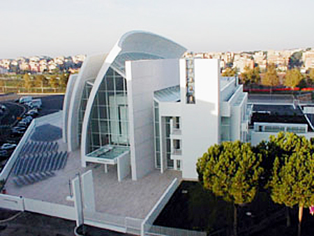
This church near Rome, Italy, designed by Richard Meier, incorporates self-cleaning concrete, one of the first to use the technology.
Research and analysis continues to grow in this field with more species documented from which to draw inspiration. Below are a few of the recent studies that are continuing to influence design, engineering, science, and technology.
Spiders can create web silk as strong as the Kevlar used in bulletproof vests. Engineers could potentially use such a material—if it had a long enough rate of decay—for suspension bridge cables, artificial ligaments for medicine, and many other purposes. (See The Biomimicry Institute for more information and the latest research at biomimicry.org)


Tensile structure bridge in Brazil
World's largest solar powered tensegrity pedestrian and cycle bridge in Brisbane, Queensland

Study for the creation of a more effective and efficient wind turbine. Image Credit: Biome Renewables
Other research has proposed adhesive glue from mussels, solar cells made like leaves, fabric that emulates shark skin, harvesting water from fog like a beetle, and more. Quieter, less disruptive wind turbines were inspired by owl feathers and maple leaves.
Recently, researchers from ETH Zurich, the Swiss Federal Institute of Technology, have been incorporating biomimetic characteristics to structural engineering problems in an adaptive deployable tensegrity bridge (tensional integrity based on a synergy between balanced tension and compression components). The bridge can carry out self-diagnosis and self-repair utilizing a machine learning algorithm.
While many codes, standards, and regulations serve as a starting point for establishing sustainability goals and targets, it is possible that by first seeking the sources of inspiration and examples from nature, the design community may improve upon these standards and create models that go beyond any of those outlined below.
Biosolids are defined by the Environmental Protection Agency (EPA) as: “nutrient-rich organic materials . . . that can be recycled and applied as fertilizer to improve and maintain productive soils and stimulate plant growth.” Biosolids that are land-applied must, at a minimum, meet the requirements of 40 Code of Federal Regulations (CFR) Part 503 (503 Rule) for pathogen reduction, metals, and vector attraction reduction. Biosolids improve the nutrients and water retention of the soil. Biosolids are beneficially used for the reclamation of soils damaged through mining, industrial uses, fire, overgrazing, coastal dredging, and infill.
The benefits of biosolids for both soil and vegetation are numerous and well recognized. Biosolids provide primary nutrients (nitrogen and phosphorous) and secondary nutrients such as calcium, iron, magnesium and zinc. Biosolids have been successfully land applied to farmland without negative consequences for decades.
Biosolids can play a critical role with respect to climate change and its impacts on soil by providing the soil organic carbon and organic matter to build soils. The addition of biosolids can also sequester carbon in the soil. Additionally, there are many opportunities to convert the chemical energy in solids to a useable form. Energy recovery options range from established systems employing anaerobic digestion and incineration, to emerging technologies, such as Supercritical Water Oxidation and hydrothermal gasification. An estimated 5,000 wastewater systems in the U.S. can likely support the construction of a biogas system to convert the organics filtered out of the wastewater into energy and soil products.

Biosolids ready for use in an agricultural application
Biosolids are wastewater solids that have been treated and stabilized. There are many ways to treat biosolids at a water resource recovery facility (WRRF). Depending on the treatment process, each biosolids process will have unique characteristics and below are descriptions of a select few.

Biosolids can range in size to small pellets to large chunks
Digestion: Anaerobic digestion is a common process to manage wastewater by reducing the amount of waste while simultaneously generating valuable byproducts. During the process, microorganisms break down the organic material in an oxygen-free environment, producing a biogas (consisting of methane and carbon dioxide) and treated solids (known as biosolids) that have reduced pathogens and odors.
Thermal Drying: Thermal drying utilizes heat to drive water out of wastewater solids and produce a Class A biosolid with approximately 90% dry solids. The drying process reduces the volume and weight of wet solids, lowering transportation and storage costs, while creating an easily handled, low odor product that can be used as a fertilizer, soil conditioner, or biofuel. At some facilities, waste heat from other utility operations is used to further reduce costs. There are some drawbacks to drying, namely higher capital costs, complex equipment requiring trained operators, and operational safety concerns, all of which must be taken into account when choosing a dryer unit.
Solar Drying: Solar dryers utilize the radiant energy from the sun to slowly dry wastewater solids. The solids are either loaded into a greenhouse or simply spread on drying beds outside. The piles are periodically mixed and aerated to promote drying and the end product from a solar drying operation is typically 75% solids. These systems don’t require as much energy input into the process compared to other drying methods but require a larger footprint and take more time to reach a final state.
Composting: Composting is an additional process to treat wastewater solids to EPA Class A biosolids regulatory standards. During the composting process, solids are mixed with woody materials and stacked into large piles. Naturally occurring microorganisms then consume available organic material and in doing so, release heat, raising the overall temperature of the pile. Once the material has been at 131 F or higher for 3 or more days, pathogens and bacteria are typically reduced to Class A levels and the compost can be used as a soil conditioner, providing that lab tests confirm pathogen destruction. Land applying the compost provides organic matter and slow-release nutrients, increases the water-holding capacity of the soil, reduces soil erosion and compaction, and sequesters carbon.
Because science and technology are crucial to mitigating natural and man-made threats to critical infrastructure and ensuring the continuity of their services, the U.S. Department of Homeland Security (DHS) Science and Technology (S&T) Directorate has established a goal to accelerate the delivery and understanding of enhanced technology that addresses the challenges of aging infrastructure. The DHS S&T Infrastructure Protection and Disaster Management Division (IDD) supports this goal by funding the creation of a research agenda to develop improved technical options for upgrading and increasing the service life of aging infrastructure.
The primary purpose of the IRVS of mass transit stations is to rank the risk in a group of mass transit stations in a community. The results of an IRVS can also be used in infrastructure-specific risk assessments and higher level assessments of threats, consequences, and vulnerabilities.
The primary purpose of the IRVS of tunnels is to rank the risk in a group of tunnels in a transportation system or region. The results of an IRVS can also be used in infrastructure-specific risk assessments and higher level assessments of threats, consequences, and vulnerabilities.
The primary purpose of the methodology is to prioritize the relative risk and resilience among a collection of buildings in a city or community, but the methodology can also be used to develop infrastructure-specific risk information for risk management activities.
The purpose of the tool is to provide security planners and first responders with helpful information for assessing the potential threat posed by explosions in urban settings. The NYC Financial District was chosen as the initial proof-of-principle for the development approach adopted for the effort. The UrbanBlast methodology was specifically developed to be extensible to other urban settings as needed in the future.
This manual, part of the new Building Infrastructure Protection Series published by the United States (U.S.) Department of Homeland Security (DHS) Science and Technology Directorate (S&T) Infrastructure Protection and Disaster Management Division (IDD), serves to advance high performance and integrated design for buildings and infrastructure. This manual was prepared as a component of the S&T program for infrastructure protection and disaster management; the overall goal of this program is to enhance the blast and chemical, biological, and radiological (CBR) resistance of our Nation’s buildings and infrastructure to meet specific performance requirements at the highest possible level.
This publication, part of the new Building and Infrastructure Protection Series (BIPS) published by the DHS Science and Technology Directorate (S&T) Infrastructure Protection and Disaster Management Division (IDD), serves to advance high performance and integrated design for buildings and infrastructure. This manual was prepared as a component of the S&T program for infrastructure protection and disaster management; the overall goal of this program is to enhance the physical resistance of our Nation’s buildings and infrastructure to manmade and natural hazards to meet specific performance requirements at the highest possible level.
This guide is a field reference book for vertical shoring, lateral shoring, and in-situ rapid strengthening and/or repair of damaged building components. This guide refines and expands on the information provided in the existing US&R Structures Specialist Field Operations Guide (FOG). This guide includes concise information - including descriptive graphics – on the current FEMA developed builtin-place shoring systems, newly designed and tested builtin-place shoring systems, the results of the most recent testing of built-in-place shoring systems, and a system by system discussion of the relevant characteristics of Manufactured Shoring and Repair and Strengthening techniques that may be able to be adapted to rescue operations. Also included in this Guide is expanded information on Building Size-Up and new Shoring Size-up information.
The Urban Blast Tool (UBT) quantifies the effects of blast in urban environments, including the influence of buildings on blast pressures propagating from explosions located in urban settings. The tool also quantifies the potential for these blast pressures to damage primary structural members of buildings and accounts for the sensitivity of several common building design types to progressive collapse due to damage of key support members. Finally, the tool evaluates the likelihood that blast pressures may damage building equipment needed for Emergency Evacuation, Rescue and Recovery (EERR) operations.
This Technical Report describes a project performed by the National Institute of Building Sciences (Institute) in partnership with the U.S. Department of Homeland Security (DHS) to address High Performance Based Design for the Building Enclosure (HPBDE). The Institute convened an expert team to develop a method for analyzing multiple performance objectives early in the project planning process. This method allows building owners to optimize their investments in building security, along with safety, energy conservation, environmental footprint and durability, in addition to evaluating the resulting risk and resilience of a proposed project.
The model of performance developed by the Project Team was integrated within an online software program specifically focused on establishing Owner Performance Requirements (OPR).The OPR Tool provides project planners with a previously unavailable resource for selecting and documenting performance goals for a project. This first-phase effort, limited to enclosure systems for new office buildings, lays the technical foundation and software framework for expanding the approach in later phases to address retrofit of enclosure systems, as well as moving on to cover the whole building and additional building types.
This manual represents a minimum standard for boiler and associated plant safety device functionality and testing. The purpose of this manual is to support the development of an individual boiler and associated plant safety device testing program for your specific facility as required by the VA. The text presents a concise and thorough treatment of boiler safety as applied to automatically-fired gas and oil, heating and process boilers and boiler support equipment servicing healthcare facilities. This Eighth Edition was prepared for use in training and conducting safety reviews for the United States Department of Veterans Affairs (VA).
Crash- and attack-resistant bollards are used to protect military and governmental buildings and domestic structures and areas of higher security levels. The choice of more robust bollards over those that are not impact resistant is based on site vulnerability assessments and risk analysis. (See UFC/ISC Security Criteria Overview and Comparison; Cost Impact of the ISC Security Design Criteria; Threat/Vulnerability Assessments and Risk Analysis.)
Non-attack-resistant and attack-resistant bollards represent radically different safe/secure response conditions. Non-attack-resistant bollards are "perceived impediments to access." Theirs is an "expectation of civility," directed primarily at drivers with prescriptions for traffic control. Traffic control, while not necessarily static in its design, adjusting as it often does to daily shifts in traffic patterns, nevertheless is predictable to those who traverse the maze of cityscapes on a daily basis. With the expectation of traffic control, the issue and design of safe/secure is more predictable. It's civilized! And, accordingly, bollard configurations are more predictable.
Contrasted with drivers who are civil and compliant with society's norms are those who plan or carry out acts of property destruction, incite terrorism, or cause the deaths of civilian, industrial or military populations. They are opportunistic, seeking for security system weaknesses and avoiding, where- and when-ever possible a facility's strengths.
Employing crash- and attack-resistant bollards in the security design involves choices from a diverse pallet of styles. It is this versatility that influences the discussion.
This Resource Page documents that the definitions of safety, security, and perimeter security design are fluid concepts; that changing threat, vulnerability, and risk assessments for any one situation can require implementation of different design scenarios. For instance, when high profile domestic industries perceive themselves to be threatened in a manner similar to that in military environments, then security design codes and standards warrant shifts from a static to a more dynamic and fluid design. Because of their versatility bollards are important participants in changing security design.
The tasks in this Resource Page are threefold:
To describe the industrial scope, costing, impact resistance, and style variations of crash / attack-resistant bollards
To show how bollards coordinate with other security designs (e.g. zones, stand-off, CPTED, landscaping, etc.)
To illustrate the emerging issue of how perimeter security design incorporates bollards randomly as a tactic to quell the impact of asymmetric terrorism.
| N Models in Market | N Manufacturers | |
|---|---|---|
| Inactive Bollards | ||
| Fixed-Deep Set | 37 | 13 |
| Removable-Deep Set | 41 | 10 |
| Fixed-Shallow Set | 41 | 10 |
| Fixed-Surface Set | ? | ? |
| Active Bollards | ||
| Automatic Retractable² | 39 | 14 |
| Manual Retractable³ | 10 | 15 |
| Turntable⁴ | 1 | 1 |
| Total | 169 | |
¹ Derived from a detailed spreadsheet inventory of 17-items describing each of the 169 models, compiled by David McGee, Concentric Security, LLC, Montgomery, Alabama ² Fully hydraulic, pneumatic, or electric, activated by push-button ³ Requires assisting mechanism: screw drive, internal gas propellant, or counter-weight ⁴ Hybrid design: bollards remain fixed on a rotating turntable
While the metrics used for stopping effectiveness of active or passive bollards are the same (see below), the differences between active and passive bollards are significant when they are compared on initial and life-cycle costs.
The installation time for all models shown in this table is two to three days.
| Rating | Equipment Cost¹ (x $1000) | Installation Cost¹ (% of equipment cost) |
K4² | 2.6 | 47 |
|---|---|---|
| K4³ | 3.5 | 50 |
| K12⁴ | 2.8 | 89 |
| K12⁵ | 3.5 | 77 |
| K12² | 3.7 | 40 |
¹ From unpublished communication; all single bollard units ² Shallow mount fixed bollard ³ Shallow mount removable bollard ⁴ Deep mount fixed bollard ⁵ Deep mount removable bollard
(Noticeably absent in the foregoing and next table is listing of K8 bollards. K8s, in recent times, and increasingly are being covered by K12 solutions.)
Illustrative manufacturer's costs in 2009 for manual and automatic retractable crash-certified active bollards vary by K-level and number of bollards per unit:
The installation time for all models in this table is three to five days for equipment and another three to four days for wiring.
| DoS Rating | Equipment Cost (x $1000) | Installation Cost (% of equipment cost) 2009 data |
|---|---|---|
| K4 | 25 to 35 | 133 |
| K4 | 15 to 20 | 75 |
| K12 | 29 to 39 | 118 |
| K12 | 43.2 | 50–75¹ |
| K12 | ~100 | 20–30² |
| 2012 (unpublished) data; three-bollard units | ||
| K4³ | 21 | 63 |
| K4⁴ | 40 | 85 |
| K12³ | 23 | 64 |
| K12⁴ | 48 | 76 |
¹ 3 bollards ² 4 bollards ³ Manual Retractable ⁴ Hydraulic Retractable
Following industry trends, the newest and now ascending innovation is the electric bollard design. Being all-electric, it avoids the waste of hydraulics, doing away with waste pumps, fluid reservoirs, and hydraulic hoses. Models cover the entire crash-resistance range, operating speed matches that of hydraulics, and installation and maintenance cost are reported to be lower. Specific manufacturer information is available at:
Retractable bollards, again compared to inactive bollards, come with a price that further exceeds front-end equipment and installation costs and adds significantly to total life-cycle costing. Additional or continuing costs include:
Safety. The potential for injury to barrier operators requires warning signs, lights, bells, and bright colors to make the presence of the barrier known, and these must be maintained. Additional costs are back-up power, emergency cut-off switches, and installation of safety options.
Security. Barrier location invites sabotage when they are left unattended in remote areas. Additional costs are for anti-tamper switches, tamper-proof screws, and roaming security guards.
Reliability. When properly maintained (an ongoing cost), barrier failure rate is less than three percent. Local staff, however, requires training by the manufacturer for everyday- type operations independent of contracted maintenance.
Maintainability. Maintenance contracts (inclusive of labor and parts) are an indispensible cost reducing down time and system vulnerability to penetration.
Environmental Challenges. Hinges, hydraulics, or surfaces with critical tolerances to weather conditions require added attention by local operators.
Architects, engineers, security designers, and end users need to understand the changing terminology associated with selecting appropriate barriers to protect their vital assets. In 2009, ASTM produced a new standard for the perimeter security industry by issuing ASTM F2656, which replaced the Department of State (DoS) SD-STD-02-01—Vehicle Crash Testing of Perimeter Barriers and Gates, Revision A, March 2003. The new ratings bring into chronological alignment the iteration of standards historically used by the Department of State, the Department of Defense (DoD) and now ASTM. Of barriers that are attack/crash-rated, they can be either formally crash-rated or engineer-rated.
Crash-rated barrier systems have been crash-tested and certified by a participating independent crash test facility. The tests are set up to ASTM or DoS specifications. Barrier system installation must replicate the testing design foundation, bollard spacing and number, beam lengths, etc., to be considered crash-rated. Manufacturers will have a certification letter from an independent testing organization, stating the barrier has passed the ASTM/DoS requirements for a certain vehicle type/weight, speed, and penetration level. Manufacturers also provide a dimensional drawing of the "as-tested" barrier system.
Engineer-rated barriers are systems that have been designed and computer-analyzed but not crashed or certified to ASTM or DoS specifications. These barriers often are interpolated from empirical data received from the results of crash-rated systems. Computer simulation can also manipulate system variations. Engineer-rated systems can differ in terms of foundation dimensions, bollard spacing, and barrier heights and widths. Engineer-stamped drawings show individual changes that have met certain requirements, or certify designs as fully meeting the requirements.
The DoD and DoS publish updated lists of approved bollard and barrier vendors.
Knowing the threat vehicle, the velocity it is expected to attain, and the acceptable penetration distance provides the ability to select an appropriate barrier for site specific conditions around a facility. The variables considered for different test conditions include the following:
The three standards are summarized in the next table from which comes this example illustrating use of the ASTM standard, as the increasingly preferred metric:
A M30 P1 crash barrier is designed to stop a Medium Duty Truck (M) traveling 30 mph with a penetration distance of ≤ 3.3ft
| Standard | ASTM | DOS | DOD | DOS |
|---|---|---|---|---|
| F2656-07 | SD-STD-02.01, Rev A, March 2003 | SD-STD-02.01, Rev A, March 2003 With penetration allowance | SD-STD-02.01, April 1985 | |
| Vehicle Speed | (M) Medium-duty truck (15,000 lbs) M30 (30 mph) M40 (40 mph) M50 (50 mph) (C) Small passenger car (2,430 lbs) C40 (40 mph) C50 (50 mph) C60 (60 mph) (PU) Pickup truck (5,070 lbs) PU40 (40 mph) PU50 (50 mph) PU60 (60 mph) (H) Heavy goods vehicle (65,000 lbs) H30 (30 mph) H40 (40 mph) H50 (50 mph) |
Medium-duty truck (15 000 lbs) K12 = 50 mph K8 = 40 mph K4 = 30 mph |
Medium-duty truck (15 000 lbs) K12 = 50 mph K8 = 40 mph K4 = 30 mph |
Medium-duty truck (15 000 lbs) K12 = 50 mph K8 = 40 mph K4 = 30 mph |
| Penetration | P1 ≤1 m (3.3 ft) P2 1.01 to 7 m (3.31 to 23.0 ft) P3 7.01 to 30 m (23.1 to 98.4 ft) P4 30 m (98 ft) or greater |
Only <1m penetration allowed | L3 = 3 ft. or less L2 = 3 ft. to 20 ft. L1 = 20 ft. to 50 ft. |
L3 = 3 ft. or less L2 = 3 ft. to 20 ft. L1 = 20 ft. to 50 ft. |
| Notes | Penetration indicates the test vehicle's maximum dynamic distance of penetration after impact with the barrier. Typically, the dynamic distance is barrier face to the front of the cargo bed. The barrier penetration rating does not imply that a barrier will perform as rated in all site conditions, approach routes, and topography. Also, only single-specimen tests at a specified impact location are required by this test method, and therefore, not all points of impact can be tested and validated for the penetration rating. Other impact locations may respond differently. | |||
©2011 Concentric Security - All Rights Reserved


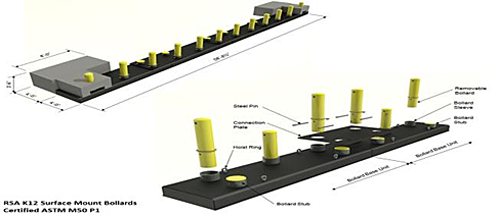


Security system design still is neither codified nor regulated, in the sense that no universal codes or standards apply to all public and private sector buildings. Government agencies (including all military services) and private sector organizations have developed numerous security design criteria. But these must be flexible and change in response to perceived emerging threats.
There are numerous standards related to perimeter security (see Resource Section). And there are just as many security system designs. Standards precede system design; design cannot be forced into a standard after the fact, an issue which has received attention, and recommends a sequence, similar to the following, leading to system design:
NEEDS DEFINITION
THREAT DEFINITION
DESIGN
This sequence is consistent with and informed by the WBDG guidance of Site Security Design Process, which proposes four hallmarks that must form the foundation of a successful and well-balanced security project:
These principles dictate the inclusion of crash- and attack-resistant bollards in any or all of their varieties and are illustrated by reference to GSA's Six-Zone Design and Landscape Architecture and the Site Security Design Process.
By focusing on zones of the site, designers are able to better understand context and how the security elements (inclusive of bollards) in each zone contribute to element performance in the other zones. Several styles of bollards are used in the first three zones:
Zone 1—Neighborhood. Bollards can be used to
Under usual risk conditions Zone 1 will be outfitted with non-crash rated bollards appropriate for traffic control. Under higher-threat conditions, crash-rated bollards can replace upright non-rated removable styles using the same receptacles or placed into receptacles reserved for random higher-threat conditions. (See Emerging Issues—discussion on Random Antiterrorism Measures-RAM.)
Zone 2—Standoff Perimeter. Bollards
Zone 3—Controlling Site Access and Parking.
In heightened alert situations, traffic access and egress can be randomly reconfigured by repositioning bollard combinations. (See Emerging Issues section.)
With the primary goal of minimizing loss of life of building occupants, the landscape architect assembles a multi-disciplinary team to address:
It does this to meet the all-important goal of "meeting security goals while preserving the ambience (values and ideals) of a free and democratic society".
Vehicular and pedestrian access. Tied to effective setback distance of vehicular access and circulation, bollards provide a protected space close to building entrances while allowing for drop-off areas for children, visitors, or disabled. The barriers' design effectiveness is measured by its prevention of straight-on lines of attack and breakthrough.
Bollards are used to prevent vehicles from leaving the roadway and circumventing efforts to restrict vehicular speed and circulation.
Parking. Surface parking areas are located to keep potential threats away from buildings, and, when bollards are used to border the perimeter of the parking area, they provide for a clear line of sight into it—a basic CPTED practice.
Security and landscape design. Bollards combine in streetscapes with other impediments to access (e.g., boulders, benches, water features, flagpoles, kiosks) to provide an aesthetically consistent extension to a building's safe zone.
Stand-off Distance. Distance in between blast and building is the most cost-effective approach to mitigate the effects of blast. Bollards define the required clear zone, which is free of visual barriers.
Physical Protective Barriers. Physical protective barriers consist of natural or manmade structures—changes in topography, vegetation, raised planted berms, fences, walls, planters, and bollards. These are employed in combinations or singularly.
Design Considerations for Vehicle Access and Entry Control. Provide traffic obstacles near entry points to slow traffic down, and offset vehicle entrances from the direction of vehicle approach to force speed reduction—both achieved with bollard-lined serpentine or chicane roadways. Vehicular access points (e.g., sally ports) should be augmented with retractable bollards.
Site Utilities. Whenever possible, site utilities should be placed underground. To do so, however, limits the use of structurally-upright bollards that can impair electric, communication, gas, and water conduits. The solution to this is to install shallow mount bollards over areas known to have underground utilities.
The foregoing discussion of site security design derives from three foundational phenomena: threat, vulnerability, and risk. These are the macro-dimensions on which engineers, intelligence experts, safety and security officers, and architects design protective systems.
It is notable that site designs take into account "clear lines of sight" to detect emerging threats. Crime Prevention Through Environmental Design (CPTED) generally and upright bollards specifically play a role here. These same lines of sight, however, also provide opportunity for those who seek to inflict damage to property or harm to personnel, thus altering prior measures of vulnerability, threat and risk and requiring renewed consideration of security design.
The terrorist attack cycle is a known process in terms of which attacks are carried out. These can be an early ally in behalf of the potential target's protective measures, involving security personnel trained in situational awareness and (the main interest here) choice and re-deployment of physical security elements and the bollard's role in that mix. The terrorist attack cycle is discernable and involves well known action points:
At some point during these steps (but primarily during the surveillance phase) the decision is reached to implement what has been described as the
Asymmetric threat: the terrorist's attempt to circumvent or undermine an opponent's strengths while exploiting his weaknesses, using methods that differ significantly from the opponent's usual mode of operation.
Adequate perimeter security measures, with their contingency plans, intend to turn this asymmetry on its head and be used against the terrorist using Random Antiterrorism Measures—RAM. Identified by military security experts as one of the best tactical measures to thwart terrorist attacks,
RAM is an asymmetric security response to asymmetric threats!
Rather than being sophisticated and invisible, those who conduct terrorist surveillance tend to be sloppy and even amateurish in their surveillance tradecraft. In this sense, they are detectable. The military takes advantage of terrorist surveillance by requiring all-personnel to undergo Awareness Training, and to implement Random Antiterrorism Measures (RAM). (See Air Force Instruction 10-245 Antiterrorism and Department of Defense Instruction 2000.16 DoD Antiterrorism Standards .
RAM is a critical element in site security design inclusive of bollard selection, and while originally a military tactic, it is becoming an all-site security practice for domestic settings, particularly high-value properties.
RAM supports the use of varying bollard patterns to disrupt terrorist surveillance operations. DoD's program proposes:
Random, multiple security measures that consistently change the look of an installation's force protection program. RAMs introduce uncertainty to an installation's overall force protection program to defeat surveillance attempts and make it difficult for a terrorist to accurately predict actions.
The U.S. NAVY definition is similar:
Random, multiple security measures that when activated, serve to disguise the actual security procedures in effect; RAMs deny the terrorist surveillance team the opportunity to accurately predict security actions. RAMs strictly vary the time frame and/or location for a given measure.
The discussion of RAM continues as part of a comprehensive perimeter security program in the concluding section.
Terrorism's Trojan Horse is the Vehicle Borne Improvised Explosive Device—capable of breaching undetected a security system or most other venues and delivering an explosive payload to unsuspecting enemy forces. If there is one attribute of terrorism that stands out it is the terrorist's weapon of choice ranging in weight from 2400 pounds up to heavy goods trucks of 65,000 or more pounds.
The DHS has defined the VBIED as a potential weapon of mass destruction, and it has proved itself as the weapon of choice in Iraq. START's Gary LaFree reports that, historically, the vehicle-borne explosive culprits were the Irish Republican Army, The Basque Fatherland and Freedom in Spain, the Taliban, and al Qa'ida in Mesopotamia. With this history to perfect the Trojan Horse, it now has shown up on the steps of America.
Mexican officials are raising concerns that Hezbollah operatives are training Mexican drug cartel enforcers in making car bombs. These car bombs show an evolution in cartel tactics, one evidence being an indictment handed down in mid-2010 by the Southern District Court in New York that showed a connection between Hezbollah—the proxy army of Iran—and drug cartels violently plaguing the U.S./Mexican border. And still more evidence being the cell-phone-detonated car bomb (the first of its kind) deployed just across the U.S.-Mexican border in Juarez.
What has been learned is that the threats in the hands of terrorists are purposefully designed to be asymmetric—circumventing or undermining strengths while exploiting weaknesses, using methods that differ significantly from the usual mode of operations.
It just so happens that the usual modes of operations, inclusive of codes and standards, are published and available to the public, terrorists included. Most industries and all military establishments, since 9/11, have published one or more security/engineering formulations, to include sections on perimeter security and site design. UFC 4-010-01 Security Engineering: Minimum Anti-Terrorism Standards for Buildings is a typical example and categorically addresses
Similarly, in Section 550 of the Homeland Security Appropriations Act of 2007 (P.L. 109-295) Congress gave DHS regulatory authority over security at high-risk chemical facilities to complete security vulnerability assessments, develop site security plans, and implement protective measures necessary to meet DHS-defined risk-based performance standards. Three of the actions focus on perimeter security:
It should come as no surprise that terrorists most likely also have downloaded and apprised themselves of both UFC 4-010-01 and P.L. 109-295 (and of other guidelines as well), conducted their usual target surveillance to determine site vulnerability, and now merely wait for the best time to attack—asymmetrically.
To put it more succinctly, security experts have advertised these basic designs.
Cutting across all security standards and threat assessments, the engineering/security/intelligence/safety team has two resources to mitigate successful attacks:
RAM is the fruit of the seasoned imaginations of engineers and security professionals to build unpredictability into the security design and function of valued facilities and their sites. Broadly defined examples amenable to RAM include
These are joined in the following example of a RAM exercise:
Principle: Removable deep-set non-rated bollards allow traffic patterns to be changed, which hampers breach (access) and escape (egress). Increased threat conditions can warrant interspersing K4-12 bollards of similar style to reduce high speed approach of vehicles near high risk targets. While these measures can cause delay in traffic, the prevention of planning and surveillance efforts by terrorists are thwarted at the perimeter. (In military settings, the intensity of RAM increases relative to the perceived threat levels—Alpha, Bravo, Charlie, Delta.)
Access. Scenario–1
Under normal conditions during peak traffic hours, the bollards are removed to allow for maximum traffic throughput. A RAM would involve insertion of bollards during peak traffic for undisclosed periods. This slows traffic but varies traffic flow to disrupt usual patterns.
Access. Scenario–2
RAM also would limit the number of access lanes by using bollards to block off lanes:
Access. Scenario–3
As traffic approaches an inspection portal (sally port), K-rated deep-set bollards on both sides of the lane will prevent last moment break-through to avoid inspection. On the exit side of the portal fully- or semi-automatic hydraulic or pneumatic bollards, rated K-4/K-8 will retract to allow entrance.
Egress. Scenario–4
Outbound/exit lanes would (1) all be open or (2) configured in a serpentine or chicane design. Random lane closures are used here for a RAM effect.
The Resource Page companion to this one on non-attack/non-crash resistant bollards introduced a way to see safety and security in tandem with each other. Safety is defined as the code- or standard-related "steady state" of some entity, i.e., it was doing what it was supposed to do. And security as the means that preserved, protected, or promoted that steady state when confronted by some natural or man made threat. On the basis of these two definitions one is able to arrive at operational definitions or performance-based measures of both concepts.
Contrasted with the rather sublime existence of traffic control bollards whose fate merely depends on sane and civil persons doing what they are supposed to do, crash- and attack-resistant bollards are designed to withstand deliberate wanton acts of destruction and death and the prolonged after-effects of terror.
The types, costs, and performance metrics of the bollards could have been cataloged in this Resource Page. But Asymmetric Threats targeting high-value properties—public and domestic—requires calculated responses to those who threaten. For this reason the surveillance stage of the terrorist life cycle is identified as requiring heightened awareness by potential target populations. This led to the tactical mixing and matching of bollard configurations known as Random Antiterrorism Measures, to confuse and render sterile would-be terrorists.
The result is a dynamic situation-relevant way to define and design perimeter security. Increasingly perimeter design must become a moving and adjusting response to a moving threat. If there is anything anti- and counter-terrorism experts have learned in recent years is that terrorists are opportunists who change their attack modalities to circumvent or undermine their opponent's strengths while exploiting his weaknesses using ever-changing methods that differ significantly from the opponent's usual mode of operation. As long as the VBIED is the preferred mode of destruction, RAM is relevant, and the cataloguing of bollards and their combinations aids in saving lives.
This Resource Page focuses on bollards that are not resistant to vehicle crashes. A companion Resource Page, The Bollard: Crash- and Attack-Resistant Models, focuses on crash- and attack-resistant bollards. Despite numerous similarities in outward appearance, the two styles represent radically different cultures.
Non-crash-resistant bollards are "perceived impediments to access." Theirs is the "culture of civility," addressing the actions of two categories of drivers:
Persons who are law-abiding and comply with civil prescriptions of orderly behavior as defined by the manner in which bollards are put to use; and
Others who border on or are potentially threatening and disrupting. For these, bollard applications are proscriptive by notifying intruders their behavior is anticipated and additional levels of security await them.
This second category potentially or, in fact, represents a "culture of destruction, terrorism, and death." This culture is addressed in the Resource Page, The Bollard: Crash- and Attack-Resistant Models. These are hardened barrier systems used to protect military and governmental buildings and structures of higher security levels. (See UFC/ISC Security Criteria Overview and Comparison; Cost Impact of the ISC Security Design Criteria; Threat/Vulnerability Assessments and Risk Analysis.)
Numerous domestic facilities use one or the other or both in tandem of the two bollard styles depending on application of the ISC Security Design Criteria, based on a project-specific risk assessment that encompasses threat, vulnerability, and consequences. Examples include:
Bollards, as functional street furniture, began with the Romans who constructed milestone markers, horse troughs, and tethering posts made of wood or stone. They later were used to protect pedestrians and buildings from horse-drawn vehicles. Bollards have long been used as short vertical posts for mooring boats and ships to docks. Our interest is in the variety of structures to control or direct road traffic.


Retractable bollards and stainless steel bollards

Urban park fixed bollard in Battery Park City, NYC
Bollards enjoy considerable variety as to their construction (cast iron, stainless steel, steel/cast iron composite, recycled plastic, plastic covers) and functional design (fixed, telescoping, removable, collapsible, and collapsible/concealable), of which more is presented below).
Surpassing in variety the diverse construction and design functions of bollards are the many settings in which bollards are used. The American Bar Association (monograph cited among references) lists 25 sites where bollards contribute to homeland security. Other uses include community services, diverse building types, parks, trails and trailheads, traffic ways, and restricted roadways. In addition are other open spaces for which bollards are specified:
Variations among the aforementioned construction, styles, and applications of bollards are too many to warrant recommending bollard selection based on mere whim or fancy. Performance-based design, however, elevates bollard selection to a more deliberate level. Performance-based design in recent years has entered building science. Its evidence is seen in the gradual shift away from prescriptive codes to proscriptive codes and standards whose applications and outcomes are measureable. This section—unique in the literature on bollards—describes a process model for arriving at a measurable performance-based bollard design.
Later sections develop how bollards are used in four specific market applications. These include (but are not limited to):
We have chosen "Safety and Security," as it is applied to restricted fire lanes, to illustrate how the model is developed. The philosophical basis for this discussion is well-known in the scientific research community as "formal theory construction," which depends on the foundational requirement for conceptual clarity.
Consensus on definitions at both the conceptual and operational (i.e., empirical/measureable) levels is essential. Without consensus security plans can be inconsistent, arbitrary, and wasteful. Consensus is a major goal of stakeholders participating in the common charrette.
A review of the literature referencing safety and security reveals the two terms often are used inconsistently, interchangeably and, consequently, inappropriately. This gives rise to confusion. For complex projects involving multidisciplinary teams, we are dealing with system concerns. Then the absence of clear situation-specific definitions of each safety and security, leads to ambiguity that works its way throughout the entire system. This applies even to the choice of bollards—simple though they may be.
Generic definitions are like skeletons, which provide the frame for derived situation-specific definitions that, in turn, can lead to performance-based design decisions.
Safety involves whatever contributes to maintaining the "steady state" of a social and physical structure or place in terms of whatever it is intended to do. Safety connotes stability over time, continuity of function, and reliability of structure.
Security is the process or means of delaying, preventing, and otherwise protecting against external or internal dangers, loss, criminals, and other individuals or actions that threaten to weaken, hinder, or destroy an organization's or site's "steady state," and otherwise deprive it of its intended purpose for being.
Gaylord National Hotel & Convention Center, National Harbor, MD
The generic definitions are applicable to any situation involving safety and security. But each situation's content will differ.
The content of a "steady state" changes from one situation to another. It can be operationally defined in terms of regulatory codes and standards, performance data, an organization's vision and mission statements, personnel policies, or operations manuals. The situation-specific "steady state" therefore is the basis for what constitutes safety and, consequently, the content of security is specifically directed toward that steady state.
In the case of a fire access lane, safety is defined as an unobstructed lane of code-specific length and width, having apparatus-weight-bearable surface, with a readily available water supply, and unimpeded access to a building threatened by fire. These qualities are referenced in both IFC 2009 and NFPA 1-2009. In addition, NFPA 1710 addresses fire apparatus response time from fire station to the inflamed building but makes only casual mention of "setup" time (approximately two minutes) that takes place within the fire lane itself.
In order to set up, bollards must be dismantled to allow apparatus entry, but the literature is lacking on how long or how much effort it takes to dismantle the bollard barriers—a performance measure addressed below. The reason the time factor is so important is that it takes only about ten minutes from time of ignition to flashover. And while two minutes are allocated for set up, not all elements involved in set up, including bollard disassembly, have been articulated metrically.
Fire lane security first and foremost involves a bollard barrier that prevents non-first responders from entering the fire lane and has signage warning non-first responders to not obstruct the area in front of the barrier. Obviously, a permanently fixed bollard would provide ultimate security, but it prevents apparatus entry. What is necessary is the selection of a bollard that honors safety by meeting the performance measures of security.
When choosing bollards to block the entrance to a protected fire access roadway, both safety and security are concerns. Fire protection engineers, architects, fire marshals or other Authorities Having Jurisdiction (AHJs), contractors, and clients all have a stake in bollard selection. All are stakeholders.
Stakeholders must collaborate to achieve performance-based design solutions. Performance and design derive from the situation-specific definition of safety. The definition of security derives from how we have defined safety. The latter is corollary to the former. Design specification, in other words, is a function of security wedded to safety.
The right design expedites easy bypass of the bollard barrier in order to set-up and commence mitigation. Also, the right design expedites a quicker return to safety conditions following mitigation and return of barriers to their role in protecting the entrance to the access roadway. (Five common market-available bollard designs used to address safety and security appear below.)
The foregoing discussion is summarized in the following figure:
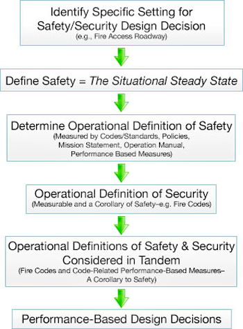
Greater design demands have been placed on bollard manufacturers to satisfy all stakeholders. Prominent among the design issues is the need to balance and optimize both safety and security needs. This issue is expressed in two fire-lane-related principles:
These principles address a time-related design issue. Both removable and collapsible bollards have been used in recent years as barriers to fire access roadways. There are five market-available designs that address the two principles, but with different degrees of efficiency.
The following artist's renditions show in ascending order of efficiency how the principles are met. That is, each of the five styles, based on in-the-field trials, require different amounts of time—from more to less—to dismantle and allow apparatus and crews to enter the fire lane.
What results here is that:
A performance-based measure pertaining to bollards is tied to a performance-based measure of apparatus set up time! In a word, the faster set up is accomplished, the faster water is applied before possible flashover. Performance-based bollard design is ultimately tied to saving lives and property!
Style 1: Padlocked Removable; 60–75 seconds to remove

Style 2: Hydrant Wrench Removable; 50–60 seconds to remove

Style 3: Padlocked Collapsible; 30-–5 seconds to collapse and pass over

Style 4: Hydrant Wrench Collapsible; 20 seconds to remove and pass over

Style 5: Collapsible by Apparatus Bumper Force; 5 seconds to collapse and pass over
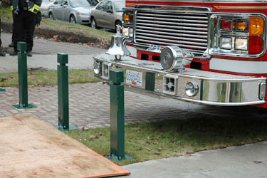
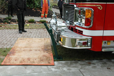
The padlocked design assumes that all first responders have a readily-accessible key to the lock box and that padlocks work under all conditions, E.g., rust and debris can make locks in-operable, and climatic conditions (rain, sand, dust, snow, mud) could make it difficult to find the locks. Failing a working lock, the only alternative is a bolt cutter, and this is a lengthy two-person job. Bollards using the fire hydrant wrench have an advantage, since all first responders carry the wrench as standard equipment. The collapsible bumper-force design responds to any first responder's slow deliberate bumper force, whether it is from the fire apparatus or an EMS or law enforcement vehicle. This bollard's breakaway design is capable of an easy on-site repair following emergency conditions. In the final analysis, the issue has to do with meeting the performance-based design requirements derived from how safety and security are defined.
Educational settings are an apt setting for bollard use for safety and security. In the most general sense, bollards provide visual access to school grounds, increase a sense of ownership and territoriality for occupants, and control access to buildings and grounds by individuals and vehicles. However, in practice, the use of bollards is much more widespread.

Lasell College in Newton, Massachusetts
In the United States, there are over 17,000-school districts and in excess of 120,000 K-12 schools. In addition, there are well over 4,000 colleges and universities. The membership of the Committee of Architects for Education of The American Institute of Architects numbers in excess of 8,000. The National Clearinghouse for Educational Facilities (NCEF), managed by the National Institute of Building Sciences has made a major investment to promote safe schools and four-year colleges and universities. NCEF has compiled the largest bibliographical listing of publications, case studies, conference and governmental proceedings, legislative mandates, and assessment checklists on school safety. Indeed, educational facilities comprise a major industry for safety and security, which is why they are considered here.
The University of Connecticut, on page 12 of its Division 2 Master Plan describes its use of bollards:
Bollards should be used in areas where a clear delineation between vehicular traffic and pedestrians is desired such as at the mouth of major pedestrian walkways where they empty onto streets. Bollards restrict vehicular movements while providing for unimpeded pedestrian circulation.
Anyone venturing into planning and designing for bollard use at educational facilities should use two of NCEF's assessment checklists that are bollard-relevant. The Outdoor Athletic Facilities and Playgrounds checklist addresses
The School Grounds and Site Access Control checklist covers a broader spectrum of areas for which there are nearly thirty bollard applications among which are:
Concentric circles of protection (CCP, also referred to as "intervention" or "buffer zones") involve bollards and are part of a whole system approach to site preparation. The U.S. General Services Administration advocates a six-zone protection system inclusive of perimeter buffer zones, where security begins at the site perimeter and gradually moves to the interior of a building. (The GSA design is addressed again in the Emerging Issues section.)
Bollards define traffic entrances to a site and as removable barriers at alternative entrances. Perimeter design gradually directs vehicles along an indirect (circular, convoluted) route toward the inner areas of a campus to prevent straight-on traffic directed toward buildings. For buildings bordering a roadway, permanent/fixed-in-place concrete-filled bollards aligned in a row adjacent to the building to protect (harden) its outer shell.
The concentric circles can extend to the innermost areas of a campus, providing setback distances and clear zones protecting building and walkway entrances, pedestrian parks, utilities enclosures, fire hydrants, loading zones, parking lot pay stations, or highly sensitive scientific laboratories.
The National Crime Prevention Institute advocates that, "the proper design and effective use of built-in environmental factors lead to the reduction in fear and incidence of crime and an improvement of the quality of life." This is the fundamental concept behind CPTED. (See Emerging Issues section on use of CPTED in connection with the GSA perimeter zone design.)
CPTED provides guidance in designing crime prevention strategies to provide for a clear border or boundary to define controlled space. These are achieved physically or symbolically to achieve security zones, using shrubbery, fences, signs, distance, open or uneven terrain, or clear line of sight for natural surveillance.
Territorial reinforcement secured through CPTED often involves bollards in the landscape design.
The goal of traffic calming is to reduce vehicle speeds, improve safety, and enhance quality of life. Most applications, which include bollards among a variety of options, focus on engineering measures (as opposed to education and enforcement) that compel drivers to slow down. In this sense traffic calming differs from the use of barriers to divert traffic as discussed in the foregoing discussions. Bollards are used for two types of calming. Volume control measures address cut-through traffic problems by blocking certain movements. Speed control changes vertical or horizontal alignment or narrowing the roadway. (See Emerging Issues section where code changes will impact traffic calming designs currently in use.)
Bollard applications in conjunction with traffic intersections, speed bumps, and sharp turning radii were used to prepare for the Republican Convention in New York City. Israel's Traffic Research Institute reduced accidents by placing bollards at highway exit gore areas in order to control traffic streams.An exceptional case study involves New York City's use of bollards.
Rethinking Bollards — How Bollards Can Save Lives, Prevent Injuries and Relieve Traffic Congestion in New York City . Transportation Alternatives: July 2007.
The foregoing discussions show that the bollard is one of the most versatile components in comprehensive integrated design planning and design execution. The bollard also exhibits qualities applicable to each of WBDG's Design Objectives—rendering it, as shown here, a tool worthy of more than casual consideration.
This section links to each of the eight Design Objectives and follows this with bollard-specific vignettes appropriate to each Objective.
The Americans with Disability Act (ADA) led to Standards for Accessible Design and discussions thereon led subsequently to potential conflicts between tenets of the Act and bollard-specific issues such as safe/secure and the impact on access and aesthetics. The potential for conflict often divides on whether it is a federal or a non-federal facility in question, such as in discussions about walking trails and bicycle paths. Such discussions seek to resolve conflicts between the restriction of access for security reasons and the removable of barriers to allow access.

American River Trail in Redding, California
Rancho San Rafael in Reno, Nevada
ADA also enters the discussion when building egress points that exit onto a fire access road and wheelchair users can be expected to traverse the bollards fronting the access road. The spacing of bollards should have a minimum clear distance between them of at least 3 feet in order to meet the requirements of the ADA but no more than 5 feet to respond to the minimum width of a vehicle.
The breadth of design styles of bollards renders them easy candidates to complement a broad spectrum of building architectural and landscaping designs. While some applications use an unfinished steel or cast iron bollard right out of the box that requires refinishing in several years, others choose powder-coated models or those that on special order enjoy up to five dozen weather-resistant colored finishes (which speaks to the issue of cost-effectiveness; see below).
Prudent aesthetic choice of bollards in connection with historic preservation plays several functions: they introduce visitors entering a site to a style that complements the main building; through traffic calming, so that visitors are asked to approach a building with a sense of reverence for times past; they play a part in protective landscaping setbacks and parking space design; and they provide, finally, a respectful portal through which visitors ascend to the main entrance.

Permanent dome-type bollard
Cost-effectiveness occurs at both the intrinsic and extrinsic levels. Extrinsic considerations are discussed below in the section on Functional-Operational.
Intrinsic considerations apply to the bollard itself. The choice of design dictates how cost effective the bollard is. Permanently sunk concrete filled iron bollards have utility until new site development, building renovation or expansion requires that the bollard be removed—always with difficulty. Removable or collapsible stainless steel bollards easily yield to the owner's needs and retain their handsome appearance. Weather resistant coatings that are factory applied circumvent the need for maintenance crews to remove rust and apply new coats of paint.
The City of Stirling, Western Australia in 2002 conducted a cost benefit analysis comparing Tanolith Pine post and rail barriers with dome-type bollards for use as barriers around all reserves in the city—a $2.5 million investment. The following points summarize why bollards were selected:
FEMA in 2003 conducted a cost-benefit analysis of 43 strategies to provide safety to school campuses (see FEMA 428, page 2–29). These were arranged on an ordinal scale progressing from "less protection / less cost / less effort" strategies on the lower end of the scale to "greater protection / greater cost / greater effort" strategies at the upper end of the scale. Of the 43 strategies, seven could be met with the use of bollards. Despite the fact that bollard cost remains relatively constant from one application to another, three of the higher cost quartiles included two bollard strategies each, and the least cost quartile had one bollard application. The conclusion is that costly high demand strategies can be met with low cost bollards.
The National Clearing House for Educational Facilities in 2008 published "Low-Cost Security Measures for School Facilities" based on NCEF Assessment Guides. Either directly or by implication bollards are acceptable low cost measures.
Extrinsic life cycle costing plays a functional-operational role: how well does the bollard do its job and thereby prevent costly consequences had the bollard otherwise failed in its purpose. The questions we ask in our evaluations follow the use of bollards for concentric circles of protection, CPTED, safety and security, and traffic calming: Did it work or not; is the bollard worthy of continued use?
Functional-Operational and Productive considerations also apply at the behavioral and psycho-logical levels. Do bollards, as part of site design and consistency with the aesthetics of the pre-vailing architecture, contribute to a sense of well-being?
The bollard in its modern form, while retaining all its historical contributions to safety and security (see section above on Performance-Based Design), has leapt ahead to full membership status in integrated whole building design (WBD) considerations. WBD, in fact, is to be credited with having elevated the bollard from the status of a design appendage to a full member in good standing.
Bollards play a key role in optimizing the use-potential of a site and limiting harm to operational and maintenance practices. They remind daily users of the overall integrity that a building and its environs portray. They warn potentially errant intruders that their intentions have been anticipated even during initial design planning. Bollards, standing in pairs or as long lines of sentinels are integral players in sustainable design.

In some situations, however, safety, security and sustainability must be balanced. The use of bollards, reinforced planters and site furnishings to withstand assaults by moving vehicles can result in undesirable increased development of open space, habitat disturbance, and possibly erosion. (See, e.g., one of the nation's most admired sustainability efforts—the University City District in Philadelphia: Glenn Rosenberg, "Sustainable Security," College Planning and Management, April 2009.)
Representatives of the International Code Council and the Congress for New Urbanism late in 2009 approved for comment a performance-based guidance that would prohibit traffic calming devices—inclusive of bollards—as "design elements of fire apparatus access roads "unless approved by the local fire code official. Early in 2010, ICC's Joint Fire Service Review Committee approved the code change for inclusion in IFC 2012. While this change might expedite traffic flow contiguous to strip mall fire lanes without threatening effective fire crew responses, it raises serious questions about and threat to the traditional exclusivity of the area fronting the entrance of fire lanes dedicated to high rise buildings.
The National Wildland Urban Interface Counsel was formed in mid-2010 to address the national concern over wildland fires contiguous to urban areas that impact 70,000 communities, 46 million homes, and 120 million people across America. Many of the more than 1000 National Recreation Trails that are heavy users of bollards are located in the wildland urban interface. Representatives of the national organization—American Trails—have the opportunity to address the potential expanded role of bollards in preventing wildland urban interface fires.
Approved in 2007, the General Services Administration's six-perimeter zone security plan is planned for use with 2000 buildings across America. The outermost zone will be a 360 degree area encompassing civilian/domestic neighborhoods inclusive of the infrastructure normally found in a full-bore community. To the extent the eight parameters of WBDG's Design Objectives play a role in designing both the GSA projects and the civilian zone, the possibility exists for unintended consequences to negatively impact the civilian sector relative to bollard and other security infrastructure use. In complex urban systems, particularly those encompassing demographic diversity, unintended consequences are frequent occurrences of planned change. To the extent GSA's security design has the potential for negatively impacting the domestic neighborhood encompassed by Zone 1, then planners versed in CPTED will have a major challenge in ameliorating the appearance of an "armed camp" fraught with bollards and other evidences of physical security.
The use of bollards, when analyzed from the perspective of Whole Building Design, has the potential of involving more stakeholders of diverse backgrounds than under past planning efforts. And to the extent that performance-based design is involved in the planning and bollard-selection process, the stakeholders will be required to possess greater analytical abilities. The charrette, therefore, will become a more technical deliberative process.
<p>Replaced by: <a href="/dod/ufc/ufc-4-740-01nf" target="_blank">UFC 4-740-01NF</a></p>
This guide should be used to stimulate innovative design and renovation strategies with the intent of making bowling centers vibrant, exciting, and inviting family entertainment. The standard provided here will help you to deliver the world-class facilities and services our customers need and deserve.
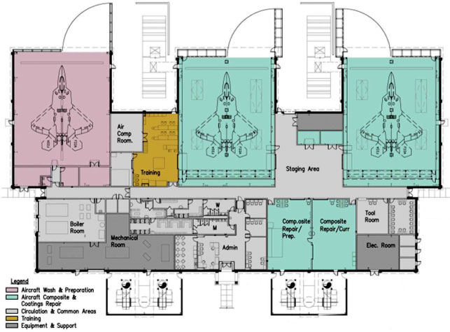
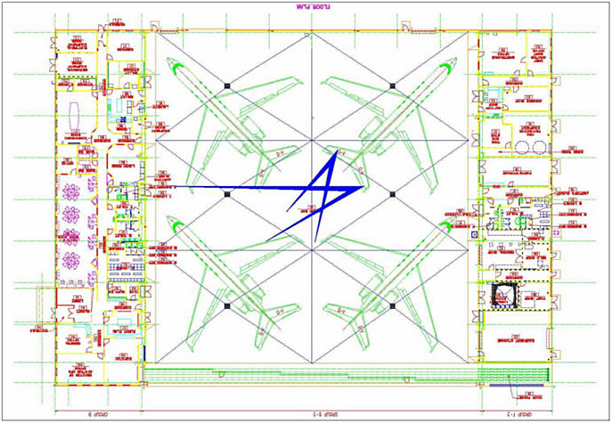