Introduction
This paper reviews the problems created by infiltration and exfiltration in buildings, and the design considerations of an air barrier system to control the problems. It explains the air pressures on buildings, the fundamentals of controlling those pressures, air barrier material requirements, combination "air and vapor barriers," and the required properties of air barriers systems. Specific designs will be reviewed, and warm-side air and vapor barriers vs. cold-side air barrier systems compared. The complexities of the "airtight drywall approach," or "ADA," (Lstiburek and Lischkoff, 1986) are also discussed. Finally, the paper will review roof air barrier concepts.
Description
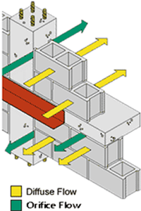
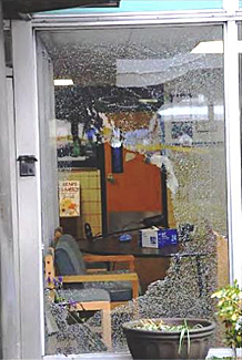
Fig. 1
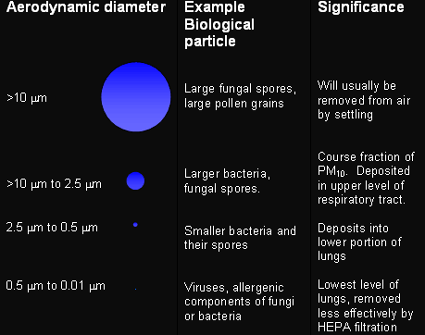
Infiltration and exfiltration of air in buildings have serious consequences, because they are uncontrolled; the infiltrating air is untreated and can therefore entrain pollutants, allergens, and bacteria into buildings. The accompanying change in air pressures can disrupt the delicate pressure relationships between spaces that HVAC systems create by design, in buildings such as hospitals, where infection control and patients' very lives may depend upon maintaining those relationships, and laboratories, where pollutant control is essential. Disrupted air pressure relationships can move pollutants from spaces where they should be contained, into other spaces where they are not desired. For example, pollutants can move from such areas as storage rooms or garages under buildings into living or working spaces and cause indoor air quality problems. Another serious consequence of infiltration and exfiltration through the building enclosure is the condensation of moisture from the exfiltrating air in northern climates, and from infiltrating hot humid air in southern climates, causing mold growth, decay, and corrosion that cause health problems and durability problems with premature building deterioration. Unlike the moisture transport mechanism of diffusion, air pressure differentials can transport hundreds of times more water vapor through air leaks in the enclosure over the same period of time (Quirouette, 1986). This water vapor can condense within the enclosure in a concentrated manner, as the air hits a surface within the assembly that is at a temperature below its dew-point (Fig. 2).
Air leaks through the building enclosure can take one of several forms:
- Orifice flow
- Diffuse flow
- Channel flow
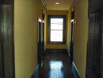
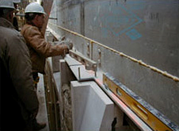
Orifice flow occurs when the air entry and exit are in a linear pathway, such as in the crack between a window rough opening and its frame (Fig. 1).
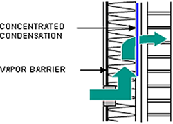
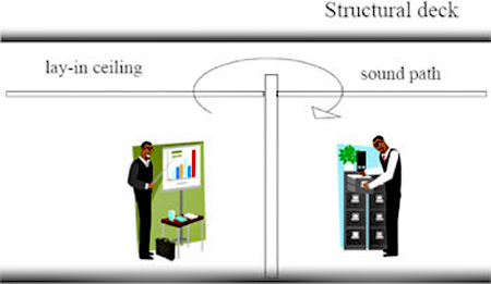
Fig. 2: Channel Flow
Diffuse flow happens when materials are used in the enclosure that are ineffective in controlling air infiltration and exfiltration due to many cracks or their high permeance to air, such as fiberboard or uncoated concrete block. Channel flow is probably the most common and serious of all types of air leaks and is shown in Fig. 2. The air entry point and exit point are distant from each other, giving the air enough time to cool below its dew point and deposit moisture in the building enclosure.
Lastly, air infiltration and exfiltration are the cause of unnecessary energy consumption in buildings due to the added heating and cooling loads and the additional humidification or dehumidification needed (Emmerich, McDowell, Anis, 2005).
Air Pressures That Cause Infiltration and Exfiltration
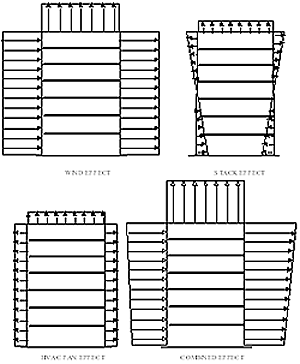
There are three major air pressures on buildings that cause infiltration and exfiltration:
- Wind Pressure
- Stack Pressure (sometimes called chimney effect or buoyancy)
- HVAC Fan Pressure
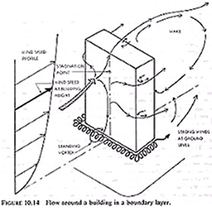
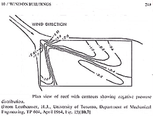
Wind
The average annual wind pressure on buildings is of significance in calculating energy or moisture-related air leakage in buildings. When averaged out over the course of the year, it is about 10-15 mph (0.2-0.3 psf) (10-14 Pa) in most locations in North America. (Wind and Air Pressures on the Building Envelope) Wind pressure tends to pressurize a building positively on the façade it is hitting, and as the wind goes around the corner of the building it cavitates and speeds up considerably, creating especially strong negative pressure at the corners and less strong negative pressure on the rest of the building walls and roof (Figs. 3 and 4), (Hutcheon and Handegord, 1983).
Stack Pressure
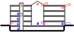
Fig. 5
Stack pressure (or chimney effect) is caused by a difference in atmospheric pressure at the top and bottom of a building due to the difference in temperature, and therefore, a difference in the weight of the columns of air indoors vs. outdoors in the winter. Stack effect in cold climates can cause infiltration of air at the bottom of the building and exfiltration at the top, as seen in Fig. 5. The reverse occurs in warm climates with air-conditioning.
Fan Pressure
Fan pressure is caused by HVAC system pressurization, usually positively, which is fine in warm climates but can cause incremental enclosure problems to wind and stack pressures in heating climates. HVAC engineers tend to do this to reduce infiltration (and with it, pollution) and disruption of the HVAC system design pressures relationships. Fig. 6 shows each of these pressures separately and a combined diagram.
The National Institute of Standards and Technology reports that the added energy to heat and cool buildings due to infiltration and exfiltration can be anywhere from 10% in cooling climates to 42% in heating climates (NISTIR 7238).
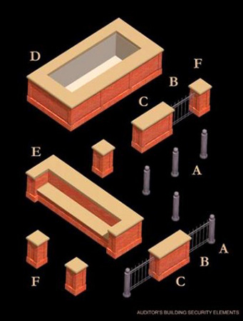
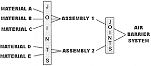
The concept is to select and target a component of the wall or roof that is air impermeable and to deliberately make it an airtight "assembly" by sealing the joints and penetrations. This assembly of materials is connected to adjacent assemblies or components such as windows, doors, or the roof air barrier component, by sealing or joining the airtight component of assembly A to the airtight component of assembly B. The air barrier system above grade is also connected to the foundation walls and basement slabs to complete the air barrier system of the building. Air tightening below-grade walls and slabs prevents entry of dangerous gases such as radon, and pollutants from agricultural activities and brownfields, due to depressurization of spaces with their enclosure in contact with the soil.
The important features of an air barrier system in a building are: Continuity, Structural Support, Air impermeability, and Durability.
Continuity
To ensure continuity, each component serving its role in resisting infiltration, such as a wall or a window assembly or a foundation or a roof, must all be interconnected to prevent air leakage at the joints between materials, components, assemblies, and systems and penetrations through them, such as conduits and pipes.
Structural Support
Effective structural support requires that any component of the air barrier system must resist the positive or negativestructural loads that are imposed on that component by wind, stack effect, and HVAC fan pressures without rupture, displacement or undue deflection. This load must then be safely transferred to the structure. Design consideration must determine adequate resistance to these pressures by fasteners, tapes, adhesives, etc.
Air Impermeability
Materials chosen to be part of the air barrier system should be chosen with care to avoid selecting materials that are too air-permeable, such as fiberboard, perlite board, and uncoated concrete block. The air permeance of a material is measured using ASTM E 2178 test protocol and reported in Litres/second per square meter at 75 Pa pressure (cfm/ft² at 0.3" w.g or 1.57 psf). The Canadian and IECC codes and ASHRAE 90.1 consider 0.02 L/s.m² 75 Pa (0.004 cfm/ft² 1.57 psf), which happens to be the air permeance of a sheet of ½" unpainted gypsum wall board, as the maximum allowable air leakage for a material that can be used as part of the air barrier system for the opaque enclosure; the same number is required by the Advanced Buildings Core Performance (New Buildings Institute), and ASHRAE SP 102 (Advanced Energy Design Guide: Small Office Buildings). The Air Barrier Association of America considers that number the industry standard for air barrier materials.
This maximum allowable air permeance for materials is more airtight than the requirements for windows and curtain walls, but it must be remembered that windows and curtain walls are assemblies of materials and also these materials are more resistant to damage due to condensation than ordinary building materials. It is to be expected that when fairly airtight materials are assembled together by sealing, taping screws, etc., that the assembly will leak more air than the original material that is being used as the basic material ASTM E 2357 is the assembly air leakage and durability test; IECC and ASHRAE 90.1 establishes 0.2 L/s.m² at 75 Pa (0.04 cfm/ft² at 1.57 psf) as the maximum allowable assembly air leakage. An assembly is defined by ASTM E 2357. Also, when these assemblies are joined together into a whole building, the building enclosure will leak more air than the individual assemblies joined together in the first place.
In order to achieve a reasonable end result, the basic materials selected for the air barrier must be quite air-impermeable. The U.S. Army Corps of Engineers (USACE) and the Naval Facilities Command (NAVFAC) have established 0.25 cfm/ft² at 1.57 psf (1.25 L/s.m² at 75 Pa) as the maximum air leakage for an entire building (airflow tested in accordance with the USACE / ABAA Air Leakage Test Protocol (which incorporates ASTM E 779) whereas the U.S. Air Force and the International Green Construction Code (IgCC) specify 0.4 cfm/ft² @ 11.57 psf ((2.0 L/s.m²@ 75 Pa) divided by the area of the enclosure pressure boundary). A recent ASHRAE study, 1478 RP, measured the whole building airtightness of sixteen mid-to-high-rise buildings built after the year 2000; the study found that eight of those buildings were tighter than the USACE airtightness standard.
Durability
Materials selected for the air barrier system must perform their function for the expected life of the structure; otherwise they must be accessible for periodic maintenance, such as elastomeric paint coatings on concrete block.
In summary, air barrier system code requirements may require:
A continuous plane of airtightness must be traced throughout the building enclosure with all moving joints made flexible and sealed.
Air Leakage Control Compliance Alternatives:
The air barrier material in an assembly of the opaque enclosure must have an air permeance not to exceed 0.004 cfm/sf at 0.3" wg (1.57 psf) [0.02 L/s.m² at 75 Pa].
An air barrier assembly must have an air permeance not to exceed 0.2 L/s.m² 75 Pa (0.04 cfm/ sf 1.57 psf), when tested according to ASTM E 2357. The registered design professional shall determine the test air pressures adequate to simulate design conditions for the location of the project.
The whole building's air leakage rate must not exceed 2 L/s.m² 75 Pa (0.4 cfm/ sf 1.57 psf) when tested according to ASTM E779.
The air barrier system must be able to withstand the maximum design positive and negative air pressure and must transfer the load to the structure.
The air barrier must not displace under load or displace adjacent materials.
The air barrier material used must be durable or accessible for maintenance.
Connections between roof air barrier, wall air barrier, window frames, door frames, foundations, floors over crawl spaces, ceilings under attics and across building joints must be flexible to withstand building movements due to thermal, seismic, moisture content changes and creep; the joint must support the same air pressures as the air barrier material without displacement.
Penetrations through the air barrier must be sealed.
An air barrier must be provided between spaces that have either significantly different temperature or humidity requirements.
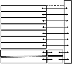
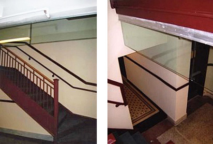
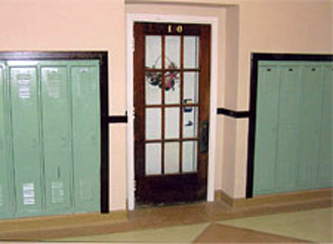
Fig. 8
Lighting fixtures are required to be special low leakage gasketed fixtures when installed through the air barrier or the air barrier must be designed around the fixture.
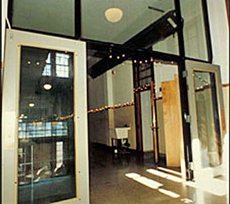
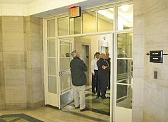
To control stack pressure transfer to the enclosure, stairwells, shafts, chutes, and elevator lobbies must be decoupled from the floors they serve by providing doors that meet air leakage criteria for exterior doors, or the doors must be gasketed (Fig. 8).
Functional penetrations through the enclosure that are normally inoperative, such as elevator shaft louvers and atrium smoke exhaust systems, must be dampered and closed off with airtight motorized dampers connected to the fire alarm system to open on call and to fail in the open position.
In addition, other pressure differentials within buildings should be controlled by the following methods:
Compartmentalizing and sealing garages under buildings with airtight walls and vestibules at building access points.
Compartmentalizing spaces under negative pressure, such as boiler rooms, and providing make up air for combustion.
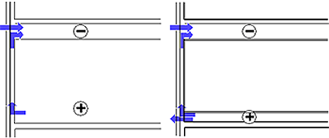
Fig. 9 and Fig. 10: Plenums connected to the exterior enclosure can move moist air through these assemblies.
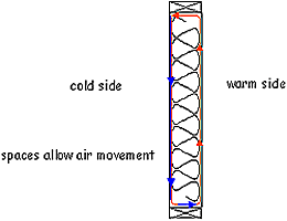
Fig. 11: Convection of moist air in enclosure assemblies can cause problems.
Decoupling supply or return floor and ceiling plenums from the exterior enclosure. If these leak air, serious consequences will arise that should be considered; the exterior walls become ducts with air forced through them, potentially causing severe condensation, microbial growth and deterioration (Figs. 9 and 10).
Controlling convection currents within enclosure assemblies caused by connecting air on the cold side to air on the warm side of insulation or the interior air by sealing the interior (Fig. 11). This is the typical mechanism of mold formation in insulated basements, where air that is adjacent to a cool concrete basement wall cools down, gets heavier and drops, pulling in warm humid air at the top of the insulated wall.
Generic materials that meet the air leakage requirements stated above are as follows (Bombaru, Jutras, and Patenaude, CMHC, 1988 ).
| MATERIAL AIR LEAKAGE |
| Thickness of Non-Measureable Airflow |
Measureable Airflow |
CFM
at 0.3"
wg |
L/(s/m²)
at 75 Pa |
| 0.006" | *Polyethylene | 0.315" | Plywood | 0.001 | 0.0067 |
| 0.060" | Roofing membrane | 0.63" | Waferboard | 0.001 | 0.0069 |
| 0.106" | Modified asphalt torched-on | 0.5" | Exterior Gypsum | 0.002 | 0.0091 |
| 0.001" | *Aluminum foil | 0.433" | Waferboard | 0.002 | 0.0108 |
| 0.060" | Sheet asphalt peel and stick | 0.5" | Particle Board | 0.003 | 0.0155 |
| 0.374" | Plywood | *Non-perforated spun-bonded polyolefin | 0.004 | 0.0195 |
| 1" | Extruded polystyrene | 0.5" | Interior gypsum board | 0.004 | 0.0196 |
| 1" | Foil-backed urethane | | | | |
| 0.5" | Cement board | | | | |
| 0.5" | Foil-backed gypsum board | | | | |
*Membranes must withstand air pressures in both directions without displacement or damage. If not fully adhered, they must be sandwiched between two board materials.
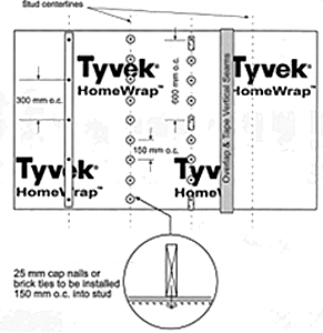
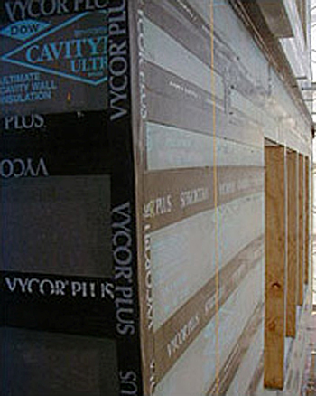
If house-wraps and other film membranes are not fully supported on both sides, as is the case in a brick cavity wall, they cannot support negative wind loads without tearing at the staples and brick anchors or rupturing under load (Bosack and Burnett, 1998). House-wraps in brick cavity walls displace under negative wind pressure and "pump" building air into the assembly, potentially causing condensation in cold climates. While testing in Canada to pre-qualify its membrane for use as an air barrier material, a manufacturer of spunbonded polyolefin discovered that to withstand negative wind pressures, the membrane needed to be stronger, and installed with fasteners having 1" diameter plastic washers, or a brick tie must be installed every 6" (150 mm) into the stud and 16" (400mm) apart (Fig. 12). Alternatively continuous strapping with a fastener every 12" (300mm) may be used. Note that products sold in Canada and the U.S. with the same name may not have the same air leakage or strength properties.
Fig. 12: Drawing of Tyvek HomeWrap membrane with 25mm cap nails or brick ties installed 150mm on center.
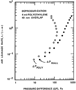
Fig. 13: Polyethylene air barrier ruptures in a wall with glass-fiber batt insulation.
It is even more difficult to make polyethylene into an air barrier. It lacks structural support when it is against glass-fiber batts and has the inherent quality of displacing and stretching, even rupturing, under high wind loads. It is also difficult to seam to itself or other materials (Fig. 13). Fastener holes through polyethylene can stretch and compromise its airtightness (Shaw, 1985).
Materials that do not qualify as air barrier materials without additional coatings are (Bombaru, Jutras and Patenaude, CMHC, 1988):
- Uncoated concrete block
- Plain and asphalt impregnated fiberboard
- Expanded polystyrene
- Batt and semi-rigid fibrous insulation
- Perforated house-wraps
- Asphalt impregnated felt, 15 or 30 lb.
- Tongue and groove planks
- Vermiculite insulation
- Cellulose spray-on insulation
Of course there are many products formulated to qualify as air barrier materials. Some of these, as well as specifications, technical help, contractor and workmen training and certification is provided by the Air Barrier Association of America.
Air Barrier Materials
The simplest approach to airtightening a wall is to select one of the layers such as the sheathing and to airtighten it using durable tapes, adhesive sheet products, fluid-applied materials, or the like. Walls constructed out of materials that are very permeable to air, such as concrete block, must be airtightened using an applied elastomeric (flexible) coating, either as a specially formulated paint, or a specially formulated air barrier sheet product, or a fluid-applied spray-on or trowel-on material. Transition peel-and-stick membranes are most commonly used at window and door perimeters, or when changing materials or wall systems (Figs. 14 and 15). Alternatively, a sheet membrane such as a peel-and-stick membrane can be used on the whole wall.
Fig. 14: Peel-and-stick membrane trim work and transitions being applied. Georgetown Law School.
Shepley Bulfinch, Architect
Fig. 15: Fluid-applied air barrier is applied to balance of wall. Georgetown Law School.
Shepley Bulfinch, Architect
Metal backpans are often used as part of the air barrier system in the spandrel areas of curtain walls.
Location of the Air Barrier
Fig. 16
The air barrier, unlike the vapor retarder, (since its function is to stop air movement, not control diffusion), can be located anywhere in the enclosure assembly. If it is placed on the predominantly warm, humid side (high vapor pressure side) of the enclosure, it can control diffusion as well, and would be a low-perm vapor barrier material. In that case, it is called an "air and vapor barrier." If placed on the predominantly cool, drier side (low vapor pressure side) of the wall, it should be vapor permeable (5-10 perms or greater).
Finally, the complexities of airtightening a building using the interior finish gypsum board are worth highlighting (Fig. 16). The airtight drywall approach or "ADA", as it is known in Canada, using the interior drywall as the airtight plane, (Lstiburek and Lischkoff, 1986) is useful in residential work where renovation is not expected for many years. In commercial work however, the intent of the designer will most likely be lost to renovation. Also, continual rewiring for data lines compromises the drywall's airtightness as the data contractor punches holes above the ceiling. It is a very complex, three-dimensional problem, and this author's best advice is, "Don't go there."
Air Barriers Subject to Temperature Changes
Air barriers on the exterior side of the insulation are subject to thermal changes and lots of movement due to expansion and contraction; therefore these joints are more difficult to keep airtight for the life of the building due to the stresses applied to the jointing tape or sealant by the thermal cycling over time. The best joint materials for these applications should be used, such as:
- Extruded silicone bedded in wet silicone.
- Wet silicone applied in a "band-aid joint" across board joints.
- Other fluid applied elastomeric air barriers products.
- Modified asphalt peel-and-stick with surface properly primed.
Figs. 17 and 18: The above two photos show foam sealant applied to all insulation board edges followed by peel-and-stick modified asphalt tape on the primed insulation sheathing boards used as the air barrier. Boston College Administration Building.
Shepley Bulfinch, Architect
Roof Air Barriers
The roof membrane can be considered an air barrier since it is designed to withstand wind loads if it is fully adhered or hot- or cold-mopped. Mechanically fastened and ballasted roof systems, because they displace and momentarily billow or pump building air into the system, do not perform the required functions of containing air without displacement. In those cases, another air barrier must be selected in the system. Either a peel-and-stick air and vapor barrier on the inboard side of the roof system (interior conditions and weather dependent), or taped gypsum underlayment board beneath the insulation can be used in a system with adhered underlayers of thermal protection board and insulation. Those layers must be designed to withstand maximum wind loads without displacement and all penetrations must be sealed. Because of the critical importance of continuity with the wall air barrier, a pre-installation conference on the air barrier system must include the trades involved in the air barrier system, such as the wall air barrier subcontractor, the window subcontractor, the sealant subcontractor, and also the roofing subcontractor, to discuss the connection between the roof air barrier and the wall air barrier, as well as the sequence of making an airtight and flexible connection between assemblies and whose responsibility it is to make that connection. It is also important to ensure that the materials being joined together are compatible.
Penetrations into roof systems, such as ducts, vents, and roof drains, must be dealt with, perhaps by using spray polyurethane foam (or other sealant) or membranes to airtighten those penetrations at the targeted air barrier layer.
Conclusion
An air barrier system is an essential component of the building enclosure so that air pressure relationships within the building can be controlled, building HVAC systems can perform as intended, and the occupants can enjoy good indoor air quality and a comfortable environment. HVAC system size can be reduced because of a reduction in the "fudge factor" added to cover infiltration and unknown factors, resulting in reduced energy use and demand. Air barrier systems in the building enclosure also control concentrated condensation and the associated mold, corrosion, rot, and premature failure; and they improve and promote durability and sustainability. Building codes now require air barriers systems, and building designers and builders should be aware of the negative consequences of ignoring building airtightness.
Applications
Buildings with air barrier systems:
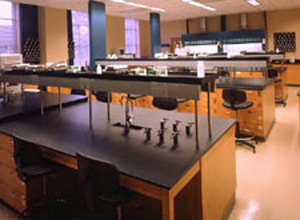
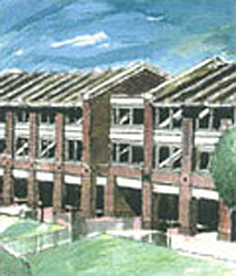
Agnes Scott College Science Building, Georgia
Building Location: Decatur, Georgia, USA
Project Size (ft², m²): 60,000 sf.
Total Building Costs: $22 million
Building Architect: Shepley Bulfinch Richardson and Abbott, Boston, Massachusetts
Completion: 2002
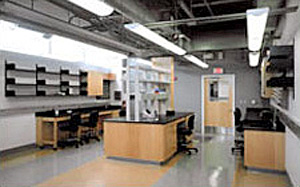
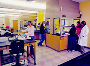
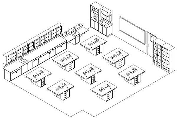
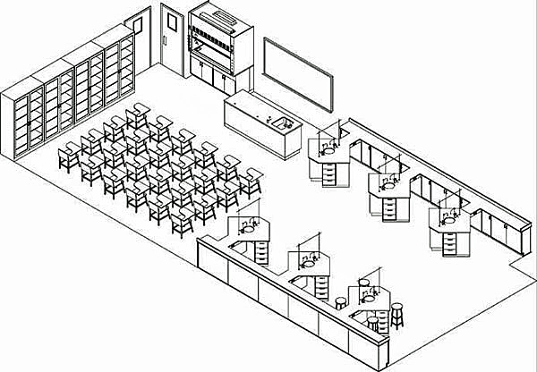
The design goal of the 104,000 sf. new science building was to integrate the sciences in order to develop multi-disciplinary study. It houses science classrooms, laboratories, faculty offices, a science reading room and the Departments of Biology, Chemistry, Physics, and Psychology. The classrooms are located in between teaching labs to allow easy flow from a lab to a classroom environment to support ASC's pedagogy. An atrium is designed as the entry element in the middle of the plan so as to symbolize the 'coming together' of the science disciplines. The new science facility is sited on the southern edge of playing fields opposite the library and campus center, forming a green.
The air barrier system is an essential part of the building enclosure of this science teaching facility, allowing the designed pressure differentials between the laboratories and the remainder of the building to be maintained without disruption caused by infiltration. The wall air and vapor barrier is a continuous modified asphalt membrane on the outside of the back-up wall, with a layer of continuous rigid insulation outside in the brick cavity.
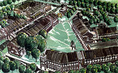
Bronson Methodist Hospital, Michigan
Building Name: New Medical Campus, Bronson Methodist Hospital
Building Location: Kalamazoo, Michigan, USA
Building Architect: Shepley Bulfinch, Boston, Massachusetts
Associate Architect: Diekema/Hamann/Architects, Kalamazoo, MI
In 1996, SBRA completed a campus master plan for phased development, which included new ambulatory and inpatient services; medical offices on the new south campus; and the renovation of existing buildings on the north campus for administrative and educational functions.
The new 750,000 sf. south campus development provides horizontal continuity for various medical specialties within a series of linked buildings. For example, surgery is located on the second level, along with inpatient and outpatient facilities, beds, and associated physicians' offices. The project also includes a Center for Women and Children, Emergency Services, Cardiology and Oncology Departments, and an integrated multi-specialty Diagnostic Center that combines traditional Radiology services within an ambulatory setting. A new 750-car garage connects on each level to complete the continuity of each department.
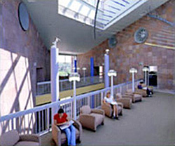
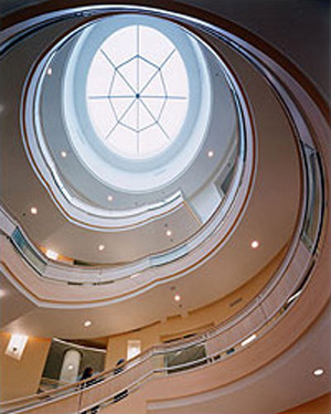
A central skylit atrium space is the "heart" of the complex and includes retail, pharmacy, chapel, food court, library, and educational spaces. These amenities create a lively and accessible facility that is oriented toward family and community use.
The new campus is a cornerstone for downtown Kalamazoo. Located at the edge of the central business district and a small-scale residential neighborhood, the new complex is sub-divided into a complex of smaller-scale brick buildings with individual canopied entries, which harmonize well with the context.
The hospital management required a building enclosure design that would promote and maintain a healthful environment with a specific mandate that walls remain dry at all times. A peel-and stick continuous air and vapor barrier on the exterior of the back-up wall, with a layer of continuous insulation outside makes this an energy efficient building enclosure. Connections were made to the roof air and vapor barrier, two layers of mopped-on asphalt felts that served also as a temporary roof during construction. Also connections were made to the foundation waterproofing membrane, to complete the air barrier system.
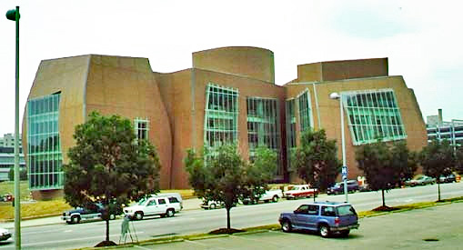
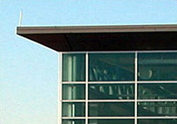
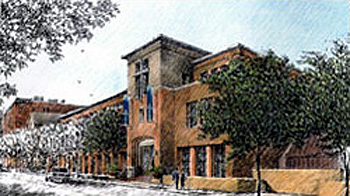
Eugene Public Library, Oregon
Building Name: Eugene Public Library
Building Location: Eugene, Oregon, USA
Building Architect: Shepley Bulfinch, Boston, Massachusetts
Associate Architect: Robertson Sherwood, Architects
The building incorporates classical proportions for a civic building, while employing contemporary details and planning ideals. This LEED-registered project incorporates into the design a concerted sensitivity to sustainable site development, indoor environmental quality, and energy conservation.
The 120,000 sf. facility occupies a one-half city block, across a main street from the Eugene Public Transportation Center. The monumental curving entry facade eases the building into the cityscape along 10th Avenue. The building is set back from the street, allowing generous plaza and planting areas, and a walled outdoor "reading garden" adjacent to the Children's Department. Outdoor plantings and a below-grade garage add to the environmental efficiency of the building by minimizing heat isles.
A dramatic three-story glass "winter garden" provides for an additional entry, with a cafe and book sale area flanking one side and public meeting rooms on the other. The library's interiors provide warmth and scaled detail throughout the main entry level and at important interior elements, such as the cylindrical stair and double-height reading areas. Extensive daylighting and "green" building materials enhance the experience of the interior space for staff and patrons alike. The entire interior volume is designed to promote the highest degree of ease of usage by the community while facilitating the operation of the library by the staff and allowing maximum flexibility for changes in the future.
The energy efficiency and indoor environmental quality goals of this project dictated a high-efficiency building enclosure. It utilizes a peel-and-stick exterior air and vapor barrier membrane wall system with a layer of continuous extruded polystyrene.
Relevant Codes and Standards
Additional Resources
- Air Leakage Characteristics, Test Methods and Specifications for Large Buildings by Proskiw, G. and Phillips, B.—Prepared for Canada Mortgage and Housing Corporation, 2001.
- Air Leakage Control by Lux, M.E., and Brown, W.C. NRC, 1986.
- Air Leakage in Buildings by Wilson, A.G. CBD 23, NRC, 1961.
- Air Leakage Tests on Polyethylene Membrane Installed in a Wood Frame Wall by Shaw, C.Y. NRC, 1985.
- The Air Permeance of Building Materials by Bombaru, Jutras, and Patenaude. CMHC, 1988.
- The Airtight House: Using the Airtight Drywall Approach by Lischkoff, J. and Lstiburek, J. 1986.
- Builders' Field Guides by Lstiburek, J. Westford, MA: Building Science Corp., 2001.
- Building Science for a Cold Climate by Hutcheon, N. and Handegord, G.O.P. National Research Council of Canada, 1983.
- Commissioning the Air Barrier System by Anis, W., ASHRAE Journal, March 2005.
- Control of Air Leakage is Important by Garden, G. K., CBD 72, NRC, 1965.
- The Difference Between an Air Barrier and a Vapor Barrier by Quirouette, R. NRC, 1985.
- Energy Impacts of Infiltration and Ventilation in U.S. Office Buildings Using Multi-zone Airflow Simulation by Emmerich, S.J. and Persily, A.K.—A paper delivered at the ASHRAE IAQ and Energy Conference, 1998.
- Investigation of the Impact of Commercial Building Envelope Airtightness on HVAC Energy Use. Emmerich, S. J.; McDowell, T.; Anis, W. - NISTIR 7238.
- "The Impact of Airtightness on System Design" by Anis, W. ASHRAE Journal, 2001.
- Stack Effect in Buildings by Wilson, A.G. and Tamura, G.T. CBD 104, 1968.
- Understanding Air Barriers by Lstiburek, J., ASHRAE Journal, July 2005.
- The Use of House-wrap in Walls: Installation Performance and Implications by Bosack, E.J. and Burnett, E.F.P. PHRC, 1998.
- Wind on Buildings by Dalgliesh, W.A. and Boyd, D.W. CBD 28, NRC, 1962.
- Wind Pressure on Buildings by Dalgliesh, W.A. and Schriever, W.R. CBD 34, NRC, 1962.


